YGP5000-01RF ID Tracking System
Crown Equipment Corporation
Click to zoom
Application Details
- Equipment Class
- DSS - Part 15 Spread Spectrum Transmitter
- Date of Grant
- Nov 08, 2015
- Application Purpose
- Original Equipment
- Date of Application
- Nov 08, 2015
- Equipment Note
- RF ID Tracking System
- Frequency Range
- 902.75000000 - 927.25000000
- Company
- Crown Equipment Corporation
- Country
- United States
Documents & Files
Document Text
Text extracted from the exhibit documents filed with the FCC. Open a document above to read the original.
Users Manual
RFID Installation Guide 2015 CROWN - TSP 6000 / 6500 / 7000 TECHNOLOGY BUSINESS DEVELOPMENT CROWN EQUIPMENT CORPORATION | 44 S Washington St, New Bremen, Ohio, 45869 RFID INSTALLATION GUIDE | Crown - TSP 6000 / 6500 / 7000 1 CONTENTS 2 Compliance ........................................................................................................................................... 2 2.1 Statement of Compliance ............................................................................................................. 2 3 Installation ............................................................................................................................................ 3 3.1 Foreword ....................................................................................................................................... 3 3.2 Bumper Assembly ......................................................................................................................... 3 3.3 Bumper Installation ....................................................................................................................... 4 3.3.1 Remove Existing Bumper ...................................................................................................... 4 3.3.2 Install New Bumper ............................................................................................................... 4 3.4 LIM Power Supply ......................................................................................................................... 5 3.5 Wiring ............................................................................................................................................ 6 3.6 Software Installation ..................................................................................................................... 7 3.7 Truck Configuration ...................................................................................................................... 7 3.8 Truck Commissioning .................................................................................................................... 7 3.9 Calibration ..................................................................................................................................... 7 3.10 Testing ........................................................................................................................................... 8 4 Appendix ............................................................................................................................................... 9 4.1 Appendix A – RFID Event Codes .................................................................................................... 9 RFID INSTALLATION GUIDE | Crown - TSP 6000 / 6500 / 7000 2 COMPLIANCE 2.1 STATEMENT OF COMPLIANCE This device complies with Part 15 of the FCC Rules. Operation is subject to the following two conditions: This device may not cause harmful interference. This device must accept any interference received, including interference that may cause undesired operation. Note: This equipment has been tested and found to comply with the limits for a Class A digital device, pursuant to Part 15 of the FCC Rules. These limits are designed to provide reasonable protection against harmful interference when the equipment is operated in a commercial environment. This equipment generates, uses and can radiate radio frequency energy, and if it is not installed and used in accordance with the instruction manual, it may cause harmful interference to radio communications. Operation of this equipment in a residential area is likely to cause harmful interference, in which case the user will be required to correct the interference at his own expense. This RFID interface module is designed for use in: BE, CZ, DK, FI, FR, DE, GR, HU, IT, LU, NL, NO, PL, PT, SI, ES, SE, UK, and USA. Modifications: Any modifications made to this device that are not approved by Crown Equipment Corporation may void the authority granted to the user by the FCC to operate this equipment. RF Exposure: To satisfy RF exposure requirements, this device and its antenna must operate with a separation distance of at least 40cm from all persons and must not be co-located or operating in conjunction with any other antenna or transmitter. RFID INSTALLATION GUIDE | Crown - TSP 6000 / 6500 / 7000 3 INSTALLATION 3.1 FOREWORD The Crown RFID system may only be installed by properly trained technicians. 3.2 BUMPER ASSEMBLY Insert the antennas first through the top where the LIM is to be mounted NOTE: Left and right is determined from a seated position in the cab looking out on the bumper Also, the slots for the antennas are "keyed" differently to avoid an incorrect mounting NOTE: Attach both cables to each antenna before bolting them to the bumper Feed the main harness through the slot (back and center) before mounting the LIM Secure the antennas ensuring that the measuring groove located on the top of the antenna is 290mm [Figure 1] from the center of the bumper Mount the LIM and connect the cables, ensuring the correct coax is associated with the corresponding antenna Figure 1 - Bumper Assembly RFID INSTALLATION GUIDE | Crown - TSP 6000 / 6500 / 7000 3.3 BUMPER INSTALLATION 3.3.1 Remove Existing Bumper Ensure that you remove the cover plate and disconnect the bumper from the current EAC wire harness Loosen and remove the counter weight bolts and remove the bumper Remove the cable protection plate Remove current EAC harness, normally this is routed under the center counter weight (if installed) 3.3.2 Install New Bumper Feed new harness through the counter weight (if installed) Connect the new harness to the LIM Tighten the counter bolts and secure the new bumper [torque to: 359 N-m / 265 lb-ft] [Figure 2] Figure 2 - Bumper Install RFID INSTALLATION GUIDE | Crown - TSP 6000 / 6500 / 7000 Re-attach the cable protection plate Mount the cove…
Text truncated - open the document above for the full version.
External Photos
Model: HD5000 Connector Side – Assembled Housing Blank Side Model: HD5000 Housing Top view Housing – Right Side Model: HD5000 Housing - Bottom Housing – Left Side
ID Label/Location Info
Top view - Picture of LIM (HD5000) with labels Side and Top view - Picture of LIM (HD5000) with labels Top, side, back views - Picture of LIM (HD5000) with labels Front, side, top views - Picture of LIM (HD5000) with labels
Internal Photos
Model: HD5000 Internal Photos All Parts and Boards Disassembled Antenna Boards – connector side Model: HD5000 Internal Photos Antenna Boards – Top side Assembled Antenna Board side Model: HD5000 Internal Photos Assembled – processor side Assembled – Side View Model: HD5000 Internal Photos Main Board – connector side Main Board – Processor Side
RF Exposure Info
NVLAP Lab code: 100414-0 FCC Part 1 Subpart I FCC Part 2 Subpart J INDUSTRY CANADA RSS 102 ISSUE 5 RF EXPOSURE REPORT FOR RF ID Reader MODEL NUMBER: HD5000 FCC ID: YGP5000-01 IC: 9610A-HD5000A REPORT NUMBER: 10766018B ISSUE DATE: 2015-OCT-14 Prepared for CROWN EQUIPMENT CORP 407 W MONROE ST NEW BREMEN, OH 45869 US Prepared by UL LLC 333 Pfingsten Rd. Northbrook, IL 60062 TEL: (847) 272-8800 REPORT NO: 10766018B DATE: 2015-OCT-09 FCC ID: YGP5000-01 IC: 9610A-HD5000A Page 2 of 11 UL LLC FORM NO: CCSUP4701I 333 Pfingsten Road, Northbrook, IL 60062, USA TEL: (847) 272-8800 This report shall not be reproduced except in full, without the written approval of . UL Verification Services Inc. Revision History Rev. Issue Date Revisions Revised By -- Initial Issue REPORT NO: 10766018B DATE: 2015-OCT-09 FCC ID: YGP5000-01 IC: 9610A-HD5000A Page 3 of 11 UL LLC FORM NO: CCSUP4701I 333 Pfingsten Road, Northbrook, IL 60062, USA TEL: (847) 272-8800 This report shall not be reproduced except in full, without the written approval of . UL Verification Services Inc. TABLE OF CONTENTS 1. ATTESTATION OF TEST RESULTS .................................................................................... 4 2. TEST METHODOLOGY ........................................................................................................ 5 3. REFERENCES ...................................................................................................................... 5 4. FACILITIES AND ACCREDITATION .................................................................................... 5 5. MAXIMUM PERMISSIBLE RF EXPOSURE ......................................................................... 6 5.1. FCC RULES ................................................................................................................... 6 5.2. IC RULES ....................................................................................................................... 7 5.3. EQUATIONS .................................................................................................................. 8 5.4. LIMITS AND IC EXEMPTION ......................................................................................... 9 6. RF EXPOSURE RESULTS ................................................................................................. 10 REPORT NO: 10766018B DATE: 2015-OCT-09 FCC ID: YGP5000-01 IC: 9610A-HD5000A Page 4 of 11 UL LLC FORM NO: CCSUP4701I 333 Pfingsten Road, Northbrook, IL 60062, USA TEL: (847) 272-8800 This report shall not be reproduced except in full, without the written approval of . UL Verification Services Inc. 1. ATTESTATION OF TEST RESULTS COMPANY NAME: CROWN EQUIPMENT CORP 407 W MONROE ST NEW BREMEN, OH 45869 US EUT DESCRIPTION: RF ID Reader MODEL: HD5000 SERIAL NUMBER: Non serialized DATE TESTED: August 20, 2015 – September 21, 2015 APPLICABLE STANDARDS STANDARD TEST RESULTS FCC PART 1 SUBPART I & PART 2 SUBPART J Pass INDUSTRY CANADA RSS 102 ISSUE 3 Pass UL Verification Services Inc. calculated the RF Exposure of the above equipment in accordance with the requirements set forth in the above standards, using test results reported in the test report documents referenced below and/or documentation furnished by the applicant. All indications of Pass/Fail in this report are opinions expressed by UL Verification Services Inc. based on interpretations of these calculations. The results show that the equipment is capable of demonstrating compliance with the requirements as documented in this report. Note: The results documented in this report apply only to the tested sample, under the conditions and modes of operation as described herein. This document may not be altered or revised in any way unless done so by UL Verification Services Inc. and all revisions are duly noted in the revisions section. Any alteration of this document not carried out by UL Verification Services Inc. will constitute fraud and shall nullify the document. This report must not be used by the client to claim product certification, approval, or endorsement by NVLAP, NIST, any agency of the Federal Government, or any agency of any government. Approved & Released For UL Verification Services Inc. By: Calculated By: Michael Ferrer Bart Mucha EMC Engineer EMC Engineer UL LLC UL LLC REPORT NO: 10766018B DATE: 2015-OCT-09 FCC ID: YGP5000-01 IC: 9610A-HD5000A Page 5 of 11 UL LLC FORM NO: CCSUP4701I 333 Pfingsten Road, Northbrook, IL 60062, USA TEL: (847) 272-8800 This report shall not be reproduced except in full, without the written approval of . UL Verification Services Inc. 2. TEST METHODOLOGY All calculations were made in accordance with FCC OET Bulletin 65 Edition 97-01 and IC Safety Code 6. 3. REFERENCES All measurements were made as documented in test report UL LLC Order#10766018A. Output power and Antenna gain data is excerpted from the applicable test reports and documentation provided by the applicant. Duty cycle was assumed worst case 100% 4. FACILITIES AND ACCREDITATION The test sites and measurement facilities used to collect data are located at 333 Pfingsten Road, Northbrook, IL 60062 USA. UL NBK is accredited by NVLAP, Laboratory Code 100414-0. REPORT NO: 10766018B DATE: 2015-OCT-09 FCC ID: YGP5000-01 IC: 9610A-HD5000A Page 6 of 11 UL LLC FORM NO: CCSUP4701I 333 Pfingsten Road, Northbrook, IL 60062, USA TEL: (847) 272-8800 This report shall not be reproduced except in full, without the written approval of . UL Verification Services Inc. 5. MAXIMUM PERMISSIBLE RF EXPOSURE 5.1. FCC RULES §1.1310 The criteria listed in Table 1 shall be used to evaluate the environmental impact of human exposure to radio-frequency (RF) radiation as specified in §1.1307(b), except in the case of portable devices which shall be evaluated according to the provisions of §2.1093 of this chapter. REPORT NO: 10766018B DATE: 2015-OCT-09 FCC ID: YGP5000-01 IC: 9610A-HD5000A Page 7 of 11 UL LLC FORM NO: CCSUP4701I 333 Pfingsten Road, Northbrook, IL 60062, USA TEL: (8…
Text truncated - open the document above for the full version.
Test Report
NVLAP Lab code: 100414-0 FCC 47 CFR PART 15 SUBPART C CERTIFICATION TEST REPORT FOR RF ID Reader MODEL NUMBER: HD5000 FCC ID: YGP5000-01 IC: 9610A-HD5000A REPORT NUMBER: 10766018A ISSUE DATE: 2015-OCT-09 Prepared for CROWN EQUIPMENT CORP 407 W MONROE ST NEW BREMEN, OH 45869 US Prepared by UL LLC 333 Pfingsten Rd. Northbrook, IL 60062 TEL: (847) 272-8800 REPORT NO: 10766018A DATE: 2015-OCT-09 FCC ID: YGP5000-01 IC: 9610A-HD5000A Page 2 of 62 UL LLC FORM NO: CCSUP4701I 333 Pfingsten Rd., Northbrook, IL 60062, USA TEL: (847) 272-8800 This report shall not be reproduced except in full, without the written approval of UL LLC Revision History Rev. Issue Date Revisions Revised By -- 2015-OCT-09 Initial Issue BM REPORT NO: 10766018A DATE: 2015-OCT-09 FCC ID: YGP5000-01 IC: 9610A-HD5000A Page 3 of 62 UL LLC FORM NO: CCSUP4701I 333 Pfingsten Rd., Northbrook, IL 60062, USA TEL: (847) 272-8800 This report shall not be reproduced except in full, without the written approval of UL LLC TABLE OF CONTENTS 1. ATTESTATION OF TEST RESULTS .................................................................................... 4 2. TEST METHODOLOGY ........................................................................................................ 5 3. FACILITIES AND ACCREDITATION .................................................................................... 5 4. CALIBRATION AND UNCERTAINTY .................................................................................. 5 4.1. MEASURING INSTRUMENT CALIBRATION ................................................................ 5 4.2. SAMPLE CALCULATION ............................................................................................... 5 4.3. MEASUREMENT UNCERTAINTY ................................................................................. 5 5. EQUIPMENT UNDER TEST ................................................................................................. 6 5.1. DESCRIPTION OF EUT ................................................................................................. 6 5.2. MAXIMUM OUTPUT POWER ........................................................................................ 6 5.3. DESCRIPTION OF AVAILABLE ANTENNAS ................................................................ 6 5.4. SOFTWARE AND FIRMWARE ...................................................................................... 6 5.5. WORST-CASE CONFIGURATION AND MODE ............................................................ 7 5.6. DESCRIPTION OF TEST SETUP .................................................................................. 7 6. TEST AND MEASUREMENT EQUIPMENT ......................................................................... 9 7. ANTENNA PORT TEST RESULTS .................................................................................... 10 7.1. ON TIME AND DUTY CYCLE ...................................................................................... 10 7.2. 20 dB AND 99% BANDWIDTH ..................................................................................... 13 7.3. HOPPING FREQUENCY SEPARATION ..................................................................... 20 7.4. NUMBER OF HOPPING CHANNELS .......................................................................... 22 7.5. AVERAGE TIME OF OCCUPANCY ............................................................................. 24 7.6. OUTPUT POWER ........................................................................................................ 27 7.7. AVERAGE POWER ...................................................................................................... 31 7.8. CONDUCTED SPURIOUS EMISSIONS ...................................................................... 32 8. RADIATED TEST RESULTS .............................................................................................. 45 8.1. LIMITS AND PROCEDURE ......................................................................................... 45 8.2. RADIATED EMISSIONS ABOVE 1 GHz ...................................................................... 46 8.3. RADIATED EMISSIONS BELOW 1 GHz ..................................................................... 52 9. SETUP PHOTOS ................................................................................................................. 58 REPORT NO: 10766018A DATE: 2015-OCT-09 FCC ID: YGP5000-01 IC: 9610A-HD5000A Page 4 of 62 UL LLC FORM NO: CCSUP4701I 333 Pfingsten Rd., Northbrook, IL 60062, USA TEL: (847) 272-8800 This report shall not be reproduced except in full, without the written approval of UL LLC 1. ATTESTATION OF TEST RESULTS COMPANY NAME: CROWN EQUIPMENT CORP 407 W MONROE ST NEW BREMEN, OH 45869 US EUT DESCRIPTION: RF ID Reader MODEL: HD5000 SERIAL NUMBER: Non serialized DATE TESTED: August 20, 2015 – September 21, 2015 APPLICABLE STANDARDS STANDARD TEST RESULTS CFR 47 Part 15 Subpart C Pass UL LLC tested the above equipment in accordance with the requirements set forth in the above standards. All indications of Pass/Fail in this report are opinions expressed by UL LLC based on interpretations and/or observations of test results. Measurement Uncertainties were not taken into account and are published for informational purposes only. The test results show that the equipment tested is capable of demonstrating compliance with the requirements as documented in this report. Note: The results documented in this report apply only to the tested sample, under the conditions and modes of operation as described herein. This document may not be altered or revised in any way unless done so by UL LLC and all revisions are duly noted in the revisions section. Any alteration of this document not carried out by UL LLC will constitute fraud and shall nullify the document. This report must not be used by the client to claim product certification, approval, or endorsement by NVLAP, NIST, any agency of the Federal Government, or any agency of …
Text truncated - open the document above for the full version.
Contact Information
Applicant
Ronald L Ziegler(Director Test & Compliance)
Test Firm
UL LLCRick Titus
Technical Specifications
| # | Rule Parts | Frequency Range | Power Output |
|---|---|---|---|
| 1 | 15C | 902.75 MHz - 927.25 MHz | 944.06 mW |
Other Applications from Crown Equipment Corporation
YGP148454
Jul 28, 2010Operator Transceiver
Equipment Class
DXT - Part 15 Low Power Transceiver, Rx Verified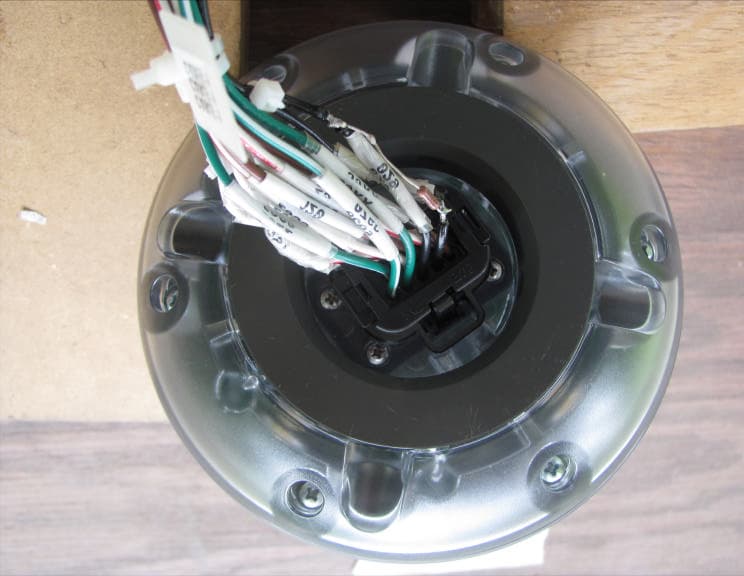
YGP144858
Jul 28, 2010Access 8
Equipment Class
DXT - Part 15 Low Power Transceiver, Rx Verified