YIBSEA157SVHF Marine Radiotelephone/Class A DSC GMDSS
SEA COM CORPORATION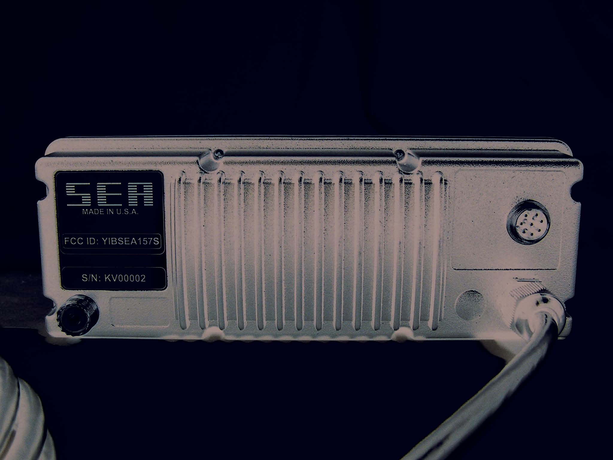
Click to zoom
Application Details
- Equipment Class
- TNB - Licensed Non-Broadcast Station Transmitter
- Date of Grant
- Oct 26, 2014
- Application Purpose
- Original Equipment
- Date of Application
- Oct 24, 2010
- Equipment Note
- VHF Marine Radiotelephone/Class A DSC GMDSS
- Frequency Range
- 162.03750000 - 162.05000000
- Company
- SEA COM CORPORATION
- Country
- United States
Documents & Files
Document Text
Text extracted from the exhibit documents filed with the FCC. Open a document above to read the original.
Users Manual
SEA COM CORPORATION. PRELIMINARY MAINTENANCE MANUAL VHF FM RADIOTELEPHONE & DSC CONTROLLER MODEL SEA 157S © Copyright 2010 SEA COM Corp. All rights reserved. SEA COM Corp. 7030 220th St. SW Mountlake Terrace, Washington 98043 TEL: (425) 771-2182 FAX: (425) 771-2650 101 019A **IMPORTANT** NOTICE TO INSTALLERS ------------------------------------------------------------------ NOTE: The safe compass distance for this equipment (As defined in Paragraph 29 of IEC Publication 92-101, Third Edition): SEA 157S VHF FM TRANSCEIVER/DSC CONTROLLER = 2.0 meters ------------------------------------------------------------------ TABLE OF CONTENTS PAGE 1. INTRODUCTION............................................1-1 2. SEA 157S SPECIFICATIONS.................................2-1 2.1 General............................................2-1 2.2 Transmitter........................................2-1 2.3 Receiver...........................................2-2 2.4 Mechanical.........................................2-2 2.5 DSC controller.....................................2-3 3. OPERATING THE SEA 157S..................................3-1 3.1 Front Panel Controls...............................3-1 3.2 Display............................................3-1 3.3 Push To Talk.......................................3-1 3.4 Radiotelephone Operating System Functions..........3-2 3.5 Digital Selective Calling Operating System.........3-7 3.6 Using Test, Calibration and Diagnostic Utilities...3-13 3.7 USA Frequency List.................................3-14 3.8 International Channel list.........................3-15 3.9 Weather Channel list...............................3-16 4. INSTALLATION............................................4-1 4.1 Preliminary Check..................................4-1 4.2 Shelf or Overhead Mounting.........................4-1 4.3 Bulkhead Mounting..................................4-1 4.4 Power Supply Wiring................................4-1 4.5 Antenna Wiring.....................................4-1 4.6 External Speaker Wiring............................4-2 4-7 NMEA 0183 and RS232 Wiring.........................4-2 5. THEORY OF OPERATION.....................................5-1 5.1 Frequency Synthesizer..............................5-1 5.2 Modulation Circuit.................................5-2 5.3 Main Receiver......................................5-2 5.4 Transmit Amplifier Chain...........................5-5 5.5 Antenna Interface Circuits.........................5-5 5.6 Automatic RF Power Control (APC) and TX Logic......5-6 5.7 TX Logic Detector..................................5-6 5.8 Power and Audio Circuits...........................5-6 5.9 Microcomputer Circuitry............................5-7 5.10 Keypad/Keypad Lighting.............................5-8 5.11 Display/Display Lighting...........................5-8 6. MAINTENANCE.............................................6-1 6.1 General............................................6-1 6.2 Recommended Test Equipment.........................6-1 6.3 Basic Performance Tests............................6-2 6.4 Transmitter Alignment..............................6-3 6.5 Receiver alignment.................................6-6 7. Block Diagram/Schematics............................7-1/7-9 LIST OF FIGURES FIG. ___________________DESCRIPTION___________________ Page 2.1 Front view of SEA 157S.............................2-4 2.2 Rear view of SEA 157S..............................2-5 4.1 Outline Dimensions of SEA 157S.....................4-3 4.2 Flush Mount Kit Drill Template for SEA 157S........4-4 6.1 Transmitter test setup.............................6-7 6.2 Receiver test setup................................6-8 7.1 Functional Block Diagram...........................7-1 7.2.1 RF Mainboard Schematic Diagram, Sheet 1............7-2 7.2.2 RF Mainboard Schematic Diagram, Sheet 2............7-2 7.2.3 RF Mainboard Schematic Diagram, Sheet 3............7-4 7.2.4 RF Mainboard Schematic Diagram, Sheet 4............7-5 7.2.5 RF Mainboard Schematic Diagram, Sheet 5............7-6 7.3 VCO Board Schematic Diagram........................7-7 7.4 Receiver Board Schematic Diagram...................7-7 7.5.1 CPU Mezzanine Board Schematic Diagram, Sheet 1.....7-8 7.5.2 DSP Mezzanine Board Schematic Diagram, Sheet 2.....7-8 7.6 Channel 70 Circuit Board Schematic Diagram.........7-9 1 INTRODUCTION This SEA 157S Service Manual provides detailed technical information for use by installation and service technicians. General operating instructions and installation drill templates are provided in the SEA 157S Operator's Handbook (SEA P/N OPR-157S) supplied with each SEA 157S. SEA COM Corp. continually strives to improve its products so that we may better serve our customers. SEA COM reserves the right to make changes to SEA 157S specifications, hardware, software or documentation at any time without notice. SEA COM's Marine Service Department is always available to provide additional help with technical difficulties. Please call SEA COM's Service Department to obtain a Return Authorization Number (RA#) before shipping equipment to SEA COM. Service parts are available through SEA COM Marine Sales/Service Departments. Please order parts using SEA part numbers found in Section 8. 1-1 2 SEA 157S SPECIFICATIONS: 2.1 GENERAL FREQUENCY RANGE: TX 155-159MHz US TX 156.0-157.5MHz RX 155-164MHz FREQUENCY RESOLUTION: 12.5kHz CHANNELS: All US, Canadian, Int'l plus 10 WX POWER REQUIREMENT: Voltage: 13.6Vdc, +/-15% Negative Ground CURRENT: Max TX: 5.5 Amps (25W) 1.0 Amps (1W) RX (STBY): 0.4 Amps RX (Max): 1.0 Amps FUSES: 7.5 Amps (External) 2.2 TRANSMITTER EMISSION: 16K0F3E & 11K2F3E (Voice) 13K5G2D (DSC) 11K2F2D (GMSK) POWER OUTPUT: 25W, 1W into 50 ohms SPURIOUS EMISSIONS: -80 dB or better SPURIOUS RADIATION: Complies with FCC 80.211(f) AUDIO HARMONIC DISTORTION: 10% max. AUDIO FREQUENCY RESPONSE: +1,-3dB of +6 dB/octave Pre-emphasis 300-3000 Hz HUM AND NOISE: 50 dB FREQUENCY DEVIATION: 5kHz max. peak …
Text truncated - open the document above for the full version.
Users Manual
SEA 157S DSC/VHF Radiotelephone Ope rator’s Manual Copyright ©2010-2020 S EA All rights reserved. S EA 7030 220th S t. S .W. Mountlake Terrace, WA 98043 US A (425) 771-2182 FAX: (425) 771-2650 www.seacomcorp.com PN: OPR-157S Rev. 1a Date: 06/2010 i TABLE OF CO NTENTS Introduction .................................................................................1 System Consists Of .................................................................2 Options and Accessories ..........................................................2 Technical Feature and Specifications .............................................3 Dimensions ............................................................................3 Electrical Specifications ..........................................................3 Wiring Diagrams ....................................................................3 Installation ...................................................................................5 Physical Mounting ..................................................................6 Power Supply Wiring ..............................................................6 Antenna Wir ing ......................................................................6 1.0 POW ER ON/OFF .....................................................................7 2.0 Keypad Function and Display Layout ....................................7 2.1 Keypad Layout ...............................................................7 2.2 Keypad Functions ...........................................................8 2.3 Soft Key Function ...........................................................9 2.4 Display Layout..............................................................10 3.0 Basic Operation ..................................................................11 3.1 Key Usage ....................................................................11 3.2 Rotary Control ..............................................................11 4.0 Selecting A Channel ............................................................12 4.1 Selecting Channel List US A/Int'l/WX ..............................12 4.2 Selecting Channel Using the Keypad ...............................12 4.3 Selecting Channel Using the Rotary Control Knob.............12 4.4 Selecting a Weather Channel...........................................12 4.5 Modify Channel Operat ion..............................................12 5.0 Volume Adjustment ............................................................13 6.0 Squelch Adjustment.............................................................13 7.0 Dimmer Level .....................................................................14 8.0 Channel 16/9 .......................................................................14 ii TABLE OF CO NTENTS (con't) 9.0 Transmitting .......................................................................14 10.0 Dual/Tri ple Watch ..............................................................15 10.1 Dual Watch ..................................................................15 10.2 Triple Watch ................................................................15 11.0 Scan / Seek ..........................................................................15 11.1 Scan ............................................................................15 11.2 Scan List - Add / Delete Channels ...................................16 11.3 Scan List - View ...........................................................16 11.4 Seek (All Scan)..............................................................16 12.0 Transmit Power ..................................................................16 13.0 Priority Channel .................................................................16 14.0 Transmitting A Distress Call ...............................................17 15.0 Transmitting A DSC Call ....................................................17 15.1 Individual DSC Call ......................................................18 15.2 Group DSC Call ............................................................19 15.3 Placing A Telephone Call With DSC ...............................19 16.0 Receiving A DSC Call ..........................................................20 17.0 Reviewing The DSC Call Log ...............................................21 17.1 Routine DSC Calls ........................................................21 17.2 Distress Call Log ...........................................................22 17.3 Missed Calls .................................................................23 18.0 Configuration Menu ............................................................23 18.1 Watch Mode Options .....................................................24 18.2 DSC Options ................................................................24 18.3 Radio Controls ..............................................................25 18.4 Scramble Options ..........................................................25 18.5 Channel Name ..............................................................26 18.6 DSC Call Lists ..............................................................26 18.7 Factory Reset ................................................................27 18.8 Set DSC ID ..................................................................27 iii TABLE OF CO NTENTS (con't) 19.0 Channel Lists ......................................................................28 20.0 Trouble Shooting ................................................................33 20.1 Unlock Warning ............................................................33 20.2 No Audio .....................................................................33 21.0 Appendix A .........................................................................34 23.0 Appendix B .........................................................................35 24.0 Appendix C ................................................…
Text truncated - open the document above for the full version.
Users Manual
Physical Mounting: Select a mounting location where the unit is easily accessed. Mount the unit in the desired position using the provided Trunnion mount or flush mounting kit. See Figures 1.2 and 1.3. Power supply wiring: CAUTION : Make sure that the provided fuse holder is installed on the power cord between the radio and the power source, and that the proper sized fuse (7.5A) is installed. Use a 12 volt +30%/-10% (10.8 to 15.6VDC) DC power source for proper operation. Do not exceed 16.0 volts. Direct connection to the battery is recommended. Connect the heavy red wire, with in-line fuse installed , to the positive (+) terminal and the heavy black wire to the negative (-) terminal. Negative ground is required for the USA/Canada version of the SEA 157S. CAUTION : If the polarity of the power wires is reversed (Black to positive, Red to negative), and power is accidentally applied to the radio, the in-line fuse will blow. It is possible that damage could also occur to some internal components. Application of voltages greater than 16.0 volts will produce the same result. (Refer service to a qualified technician.) Antenna installation and RF Exposure Safety Warning: To comply with FCC Limits for Human Exposure to Radiofrequency Electromagnetic Fields for General Population/Uncontrolled Exposure, the antenna must be mounted in such a manner as to prevent passengers or personal from coming within 1 meter (39.4 inches) of the radiating portion of the antenna. (Re: FCC OET Bulletin 65, Section 4, Public Exposure) Antenna wiring: Use only the best available 50 ohm coaxial antenna cable and connectors. The antenna must be vertically polarized. Check the antenna system for less than 1.5:1 VSWR with an in-line wattmeter before final installation. The antenna cable PL-259 connector should be tightly fastened to the antenna connector on the back of the unit. All antenna connections should be carefully protected from the weather. 6
Block Diagram
135.125MHz Q1 SA-606 21.4MHz CH 70 67.56MHz Q2 RFIN 450K 450K CH70 AF 21.850MHz CLK BPF DISC1 OSC/DBLR CH70 RCVR CLK RECEIVER MODULE RXAF U2 F5 F4 DISC 1 U1 Q2 F1,F2 21.4MHz F3 450KHz Q1 BPF SA 606 CH70 RECEIVER U16 SAV-6 ANTENNA TX IN 1/25W Q10 Q9 DRIV PA Q13 Q5 D35 LPF +13TX +13V D33 +3VRX VCO MODULE U10 MB15E03 CLKTN TXAF PLLCSSPI.DOSPICLK Q2 Q4 Q3 Y1 21.850MHz -R -N U12 U12 3VTX ONKEY LCD DISPLAY CONTRAST U17 KEYPAD + - 1/25W CLKTN Q1B Q1A Q2 Q3 Q14 Q8 Q7 U7 TLV5628 LEDS D17-D32 +13VSW 128 X 64 +13TX +13VSW U21 +13VSW SPKR AF FLASH uC U1 9.8304MHz Y1 DSP U13 SERIAL FLASH REAL TIME CLOCK CODEC WATCH RESET DOG TMP XXXX SPI_DO RS232 NMEA CH70 AF RX AF TX AF RXAF OUT SPICLK PLLCS Y2 32.768KHz DISPLAY KEYPAD MIC AF 18.432MHz Y3 VCTCXO SEA 157S FUNCTIONAL BLOCK DIAGRAM BACKLIGHTING KEYPAD BACKLIGHTING COMPUTER BOARD
Cover Letter(s)
Federal Communications Commission November 12, 2010 Office of Engineering and Technology OET Equipment Authorization Electronic Filing Dear Sir/Madam, The attached documents comprise our certification submission for our Model SEA 157S FM marine radiotelephone with DSC and Land Mobile transceiver. In addition to electronic Form 731, fee payment, and this letter, the following file attachments are included with this application: File Description 157s Certification-101021A-Cover thru Section7.pdf Test Report, Cover thru Section 7 157s Certification-101021A-Section 8 thru End.pdf Test Report, Section 8 thru End 157S Preliminary Maintenance Manual-101019A.pdf Maintenance/Service Manual 157s Operators Manual-Rev1a.pdf Operational Description/Users Manual 157S FCC ID Label_Location.pdf ID Label/Location 157S Attestation Statements.pdf Attestation Statements 157S External Photos.pdf External Photos 157S Technical Description.pdf Technical Operational Description 157S Block Diagram.pdf Block Diagram 157S Schematics.pdf Schematic Diagrams 157s Test Setup Photos.pdf Test Setup Photos 157S Internal Photos.pdf Internal Photos 157S Parts List.pdf Parts List 157S Tune-Up Procedure.pdf Tune-Up Procedure 157S RF Exposure.pdf RF Exposure Information Thank you for your attention to this certification request. If you should require further information regarding this application, I may be contacted at SEA COM Corporation at (425) 771-2182 or my mobile phone at (206) 910-1104. Sincerely, Harold G. Middleton Project Engineer SEA COM Corporation 7030 220 th Street SW Mountlake Terrace, WA 98043 FCC IDENTIFIER YIBSEA157S
Cover Letter(s)
Federal Communications Commission Office of Engineering and Technology November 16, 2010 Re: FCC ID: YIB157S FCC Registration No: 0017527912 Form 731 Confirmation No: EA175426 Correspondence Reference No: 39298 Subject: Request to change FCC ID number to YIBSEA157S On the Form 731 referenced above I made an error on the product code. It should be SEA157S not 157S. All of the test report and the maintenance manual for the radio have YIBSEA157S as the FCC identifier. I apologize for the error and would like to get it corrected. Please change the FCC ID number from YIB157S to YIBSEA157S on this application for type acceptance. Thank you. Sincerely, Gary L. Kison Senior Engineering Technician Sea Com Corp. 7030 220 th St. SW Mountlake Terrace, WA 98043 425-771-2181 x145 Fax: 425-771-2650
Cover Letter(s)
Federal Communications Commission Office of Engineering and Technology January 18, 2011 Re: FCC ID: YIBSEA157S FCC Registration No: 0017527912 Form 731 Confirmation No: EA175426 Correspondence Reference No: 39308 Subject: Reply to FCC questions regarding FCC ID YIBSEA157S In regard to FCC questions relating to Rules, Frequencies, Emissions Designators, and RF power dated November 19, 2010, our response is as follows: The SEA 157S VHF/ FM DSC radio is designed and intended for primary operations as a compliant Part 80 Maritime mobile transceiver. A. Standard production models supplied to marine dealers for resale to the boating public will be limited to compliant Part 80 Marine radio operational capabilities. 1. Frequencies for these operations are specified under Rule Part 80.373. B. Additionally, the SEA 157S design is capable of providing spectral efficient operating modes using 12.5 kHz bandwidths for voice and limited data. 1. Please note that programming of these operations are subject to controls by the manufacturer and authorized service facilities, and only available to users/operators in possession of FCC authorized frequencies for these operations. 2. Use of 12.5kHz frequencies is established in Rule Part 80.371 (c) (iii) C. Within FCC rules governing compliant Part 80 and Part 90 operations; the FCC allows spectrum allocated to VHF Public Correspondence Areas (VSPCAs) to provide service to units on land in addition to Maritime mobiles. Further, those mobile units can be authorized to operate under Part 80 and Part 90. 1. For reference; please see Rule Part 80.123, “Service to stations on land” 2. Rule part 90. 20 (11) (g)(2)(i) Table A, and (ii) Table B, (3) (4) establishes the shared use of VPCSA for land mobile 3. Further, that VHF Marine channel 25 is established as the Nationwide Interoperability channel D. Subsequently, in addition to Part 80 operations and general customer operations, SEA COM Corp is also requesting the capability to supply mobile radios to select but authorized land mobile customers that would utilize VPCSA stations for either voice or authorized data. 1. Therefore, SEA COM Corp has attached additional Part 90 test data to support its application for 12.5 kHz frequency bandwidths and applicable emissions masks for voice emissions and data emissions @ 9600BPS per 12.5kHz. 2. Our application for Equipment Authorization is first submitted as a Part 80 application and secondly as a request for acceptance under Part 90 for limited use of 12.5kHz frequencies between 156 and 162mHz. As follows, we believe that the formatted information below is correct for the requested Equipment Authorization: For licensed non-Broadcast station transmitters: FCC Rules: Frequency (mHz): Power (Watts):Freq. Tolerance: Emission Designators 80156 to 157.5255 ppm16K0F3E 80156 to 157.515 ppm16K0F3E 80156 to 157.5255 ppm13K5G2D 80156 to 157.515 ppm13K5G2D Further, for 12.5 kHz operation under Part 80 and Part 90: 80 and 90156 to 162255 ppm11K2F3E 80 and 90156 to 16215 ppm11K2F3E 80 and 90156 to 162255 ppm11K2F2D 80 and 90156 to 16215 ppm11K2F2D Sincerely, Ralph Muckelrath Director - Business Development Sea Com Corp. 7030 220 th St. SW Mountlake Terrace, WA 98043 425-771-2182 Fax: 425-771-2650
Cover Letter(s)
Federal Communications Commission Office of Engineering and Technology February 23, 2011 Re: FCC ID: YIBSEA157S FCC Registration No: 0017527912 Form 731 Confirmation No: EA175426 Correspondence Reference No: 39476 Subject: FCC Equipment Authorization System 1) Show how this device meets the requirements of Section 80.203(b) as required by KDB 149672 section 2. Our response to the above: The operating channel selection of the SEA 157S is controlled by the front panel keypad of the radio and the rotary control. The station operator may select only authorized maritime channels, which have been pre-programmed and stored in the radio’s read-only-memory by SEA COM Corporation or its authorized service personnel. The direct entry of operating frequency is not possible. A table of Part 80 frequency allocations and usage may be found in the SEA 157S Operators Manual. End users cannot not modify or re-program any pre-programmed channel of the SEA 157S. Re-programming requires the use of special software and access codes, which are available only to SEA COM Corporation and its authorized service and maintenance facilities. The special software and access codes are not available to third parties including end users, licensees, professional installers, repair shops, etc. Sincerely, Gary L. Kison Senior Engineering Technician Sea Com Corp. 7030 220 th St. SW Mountlake Terrace, WA 98043 425-771-2181 x145 Fax: 425-771-2650 [email protected]
External Photos
Page 10-2 FCC IDENTIFIER: YIBSEA157s Figure 10.1 Page 10-3 FCC IDENTIFIER: YIBSEA157s Figure 10.2
Internal Photos
Page 10-4 FCC IDENTIFIER: YIBSEA157s Figure 10.3 Page 10-5 FCC IDENTIFIER: YIBSEA157s Figure 10.4
Operational Description
Page 2-1 EXHIBIT 2 TECHNICAL DESCRIPTION, Part 2.1033(c) TYPES OF EMISSION, Parts 2.1033(c)(4), 80.207(d), 90.207(c) VOICE Mode: 16K0F3E and 11K2F3E DSC Mode: 13K5G2D GMSK Mode: 11K2F2D FREQUENCY RANGE, Part 2.1033(c)(5): Transmit: 156.0 to 157.5 MHz Receive: 155.0 to 164.0 MHz RANGE OF OPERATING POWER LEVELS , Part 2.1033(c)(6): Two carrier power levels are provided: 25 watts and 1 watt. Power level is held constant by a closed-loop operating from a sample of the RF output. See Part 2.1033(c)(10) below for details. MAXIMUM POWER LEVEL, Part 2.1033(c)(7): 25 watts carrier. The transmitter complies with 80.215 and 90.215 concerning allowable maximum power, manual and automatic power reduction and manual power override. DC VOLTAGES AND CURRENTS APPLIED TO FINAL AMPLIFIER, Part 2.1033(c)(8): Test conditions: DC voltage measured at pin 3 (Hi dc) of RF power amplifier module U16 which is the dc power input point to final power amplifier stage (See transmitter schematic diagram in Preliminary Maintenance Manual.) DC current measured into same pin as above. Transmitter operated on a frequency in the middle of its range and set to 25 watts average output power. DC Voltage: 13.6 Volts DC Current: 5.5 Amps TUNE-UP PROCEDURE, Part 2.1033(c)(9) See SEA 157S Preliminary Maintenance Manual (Enclosed), Chapter 4, "Installation" and Chapter 6, "Maintenance". FCC IDENTIFIER: YIBSEA157S Page 2-2 FREQUENCY DETERMINING AND STABLILIZATION CIRCUITS, Part 2.1033(c)(10) Block and schematic diagrams referenced below are located in Section 7 of the Preliminary Maintenance Manual. See the List Of Figures for aid in locating applicable reference drawings. FREQUENCY SYNTHESIZER: GENERAL: Refer to the functional block and schematic diagrams. The SEA 157S makes use of a multi-loop synthesizer system to provide conversion frequencies for the Receiver, and the Transmitter. The Main Transmitter synthesizer also serves as the first conversion loop for the Main Receiver and consists of the voltage controlled oscillator (VCO) Q1, RF buffers/amplifiers Q4 and Q3, synthesizer LSI chip U10, reference oscillator VCTCXO Y1, and the loop filter. VCO: The low-noise VCO is a grounded-gate JFET oscillator operating in two frequency bands as selected by Q2 and D2. D2 is "off" for transmit and L5 and L6 set the frequency band to the 155-159mHzrange. D2 is "on" for receive and L6 sets the 176.4-185.4mHz receiver local oscillator (LO) range. The tuning voltage from the loop filter is applied to varactors D4 and D5. The tuning voltage ranges from 1 to 4 volts. As the cathodes of D4 and D5 are referenced to the +8 volt supply, lower voltages correspond to higher frequencies. The entire VCO and two stage buffer is on a separate pc board located in a shielded “pocket” in the chassis casting. VCO RF AMPLIFIERS: Q4 and Q3 amplify the VCO signal up to +10 dBm (10 mW) nominal. The signal is then fed to the receiver mixer U3 via a resistive attenuator and also to the transmitter pre-driver Q10 via the Main Board diode D3. D3 is turned "on" only during transmission to supply approximately +10 dBm excitation to the transmitter amplifier chain. SYNTHESIZER CHIP: A sample of the amplified VCO signal is derived from the output of Q3 and fed to the N and A dividers of U10. The N and A divider modulus is preset by the microcomputer via the clock, data and enable digital lines. The total frequency division (N and A) reduces the RF signal down to a 12.5kHz comparison frequency at U10's internal phase detector. For example, the total division for transmission on 156.80mHzis 156,800/12.5 = 12544. For a receive frequency of 156.mHz the required LO frequency is 156.80mHz+ 21.40mHz= 178.20mHzrequiring a division factor of 178.200/12.5 = 14,256. FCC IDENTIFIER: YIBSEA157S Page 2-3 The 21.85mHz master reference oscillator is divided by a fixed 1748 modulus to produce the 12.5kHz reference frequency. The U10 phase detector output at pin 5 is tri- state and drives the loop filter. A separate lock detect (LD) output from U10 pin 14 goes low when out of lock. The LD signal is fed back to the microcomputer which disables the transmitter while in the unlocked state thus preventing the transmission of RF power outside the maximum frequency difference limits prescribed by Parts 80.209, 90.213, and 90.214”. MASTER REFERENCE OSCILLATOR: The master clock is provided by highly stable VCTCXO at 21.85mHz Y1. This oscillator has a specified frequency stability of +/-1ppm from –20 to 70 degrees C. The oscillator output is connected the input of the CMOS gate of the synthesizer IC, U10 pin 1. The output of this gate, U10 pin 2 provides a buffered 21.85mHz signal to the main and Channel 70 receiver boards. LOOP FILTER: R64 on the main PCB and R3,R4,R13,C2,C4,C5,and C19 on the VCO PCB comprise the synthesizer loop filter DESCRIPTION OF MODULATION LIMITING, POWER LIMITING AND SPURIOUS RADIATION SUPPRESSION CIRCUITRY, Part 2.1033(c)(10) MODULATION CIRCUIT: TRANSMITTER AUDIO PROCESSING: After a 20dB boost by amplifier IC U21, located on the main PCB, microphone audio is sent to be processed by the digital signal processor (DSP), U13, located on the Mezzanine PCB. The microphone audio signal is applied to the MICIN input of 16-bit audio CODEC, U8, where it is digitized and sent to the DSP. The DSP then feeds it through a digital filter/limiter process which filters the transmitter audio with a 3kHz lowpass filter. It then applies a 6db per octave pre-emphasis, limits the audio in a low distortion process and finally filters the audio again with a 3kHz lowpass filter. This method maximizes the average voice energy within the set deviation limit while minimizing audio harmonic distortion levels. DSC DATA: The digital modulation signal is generated internally in a phase continuous digital sine wave generator. It is then fed into the transmitter audio processing (within the DSP) at the input of the pre-emphasis and then applied at a level below the limiting threshold of the audio process…
Text truncated - open the document above for the full version.
Parts List/Tune Up Info
ComponentComponent Used onRefDes RefDes Listing for: 11-9-2010 157SA SEA157 VHF CLASS A Component Description ASY-157SA 157SA SUB-ASSY (TESTED) 157SA BOX-0157-01 BOX, OUTER SHIPPING,157 RADIO 157SA BOX-0157-02 INSERT, CORRUGATED,157 RADIO 157SA BOX-0157-03 INSERT, SUSPENSION PACKAGIN 157SA FAB-0157-04 BRACKET, MOUNTING 157SA FAB-0157-10 GASKET, PANEL MNT 157SA KIT-0157-99 HARDWARE KIT 157SA OPR-157S 157S ORPERATOR'S MANUAL 157SA TEM-0157-01 TEMPLATE, PANEL MOUNT 157SA PST-0157-03 PCB ASSY, VCO (UNTESTED) ASY-0157-03 ASY-0235-C01 VOL POT CABLE ASY-0157-04 PCB-0157-04 PCB, SHAFT ENCODER ASY-0157-04 SWI-0026-005 SWITCH, 20 POS ROTARY PULSE ASY-0157-04 PST-0157-05 CHANNEL 70 RECEIVER ASY-0157-05 PST-0157-08 157S CPU/DSP BOARD (UNTESTED ASY-0157-08 FAB-0157-12 BRACKET, PA MTG ASY-0157-12 HAR-0001-002 STANDOFF 1/4 RND,SW,4-40X.312 ASY-0157-12 CON-0007-010 CONNECTOR, SO239 BULKHEAD ASY-0157-C02 FER-0021-020 TOROID, T20-0 PHENOLIC ASY-0157-L6 HAR-04PL-500 SCREW, PLASK-1 #4X1/2 PH PN SS ASY-0157-M9 LBL-0101-007 LABEL, NAMEPLATE, MIC-9-2 ASY-0157-M9 MIC-0009-001 MICROPHONE (MERRY) ASY-0157-M9 CON-0024-023 TERMINAL, CRIMP FEMALE ASY-0235-C01 CON-0024-036 HOUSING 1X3,.1IN SP ASY-0235-C01 ASY-0157-08 157S CPU/DSP BOARD (TESTED) ASY-157S-01 ASY-157S-02 157S RECEIVER BOARD ASSY (TE ASY-157S-01 PST-157S-01 PCB ASSY,MAIN 157S (UNTESTED ASY-157S-01 PST-157S-02 PCB ASSY,RECEIVER 157S (UNTES ASY-157S-02 ASY-0157-04 PCB ASSY, SHAFT ENCODER ASY-157S-10 ASY-0157-C03 157 SPEAKER CABLE ASSY ASY-157S-10 ASY-0157-M9 157 MICROPHONE (MERRY) ASY-157S-10 FAB-0157-02 FRONT PANEL ASY-157S-10 FAB-0157-06 GASKET W/ADHESIVE ASY-157S-10 FAB-0157-08 GASKET, SPEAKER ASY-157S-10 FAB-157S-05 157S LENS ASY-157S-10 KNO-0011-001 KNOB,11MM PUSH-ON SPLINED,B ASY-157S-10 KNO-0011-003 CAP 11MM, PLAIN, BLACK ASY-157S-10 LBL-0157-01 LABEL, NAMEPLATE FOR 157 RA ASY-157S-10 SPE-0001-010 SPEAKER, 2.5IN, 4 OHM, 3 WATT ASY-1…
Text truncated - open the document above for the full version.
Contact Information
Applicant
Ralph F Mucklerath
Technical Contact
Sea Com Corp.Hal Middleton
[email protected]425-771-2182
7030 220th st. SW · Mountlake Terrace, Washington · United States
Technical Specifications
| # | Rule Parts | Frequency Range | Power Output | Emission | Tolerance |
|---|---|---|---|---|---|
| 1 | 9 | 162.0375 MHz - 162.05 MHz | 1 W | NOTE 2 | 5 ppm |