YIFCNI2G24Cellular Data Communications Equipment
Mercury Instruments LLC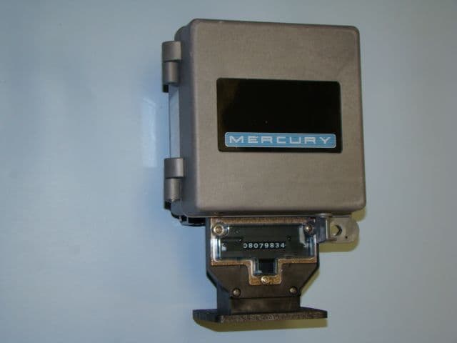
Click to zoom
Application Details
- Equipment Class
- CYY - Communications Receiver used w/Pt 15 Transmitter
- Date of Grant
- Jul 11, 2010
- Application Purpose
- Original Equipment
- Date of Application
- Jun 09, 2010
- Equipment Note
- Cellular Data Communications Equipment
- Frequency Range
- 824.20000000 - 848.80000000
- Company
- Mercury Instruments LLC
- Country
- United States
Documents & Files
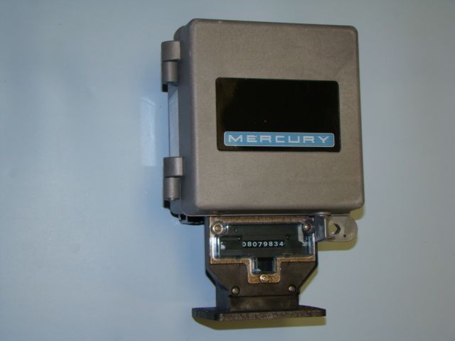
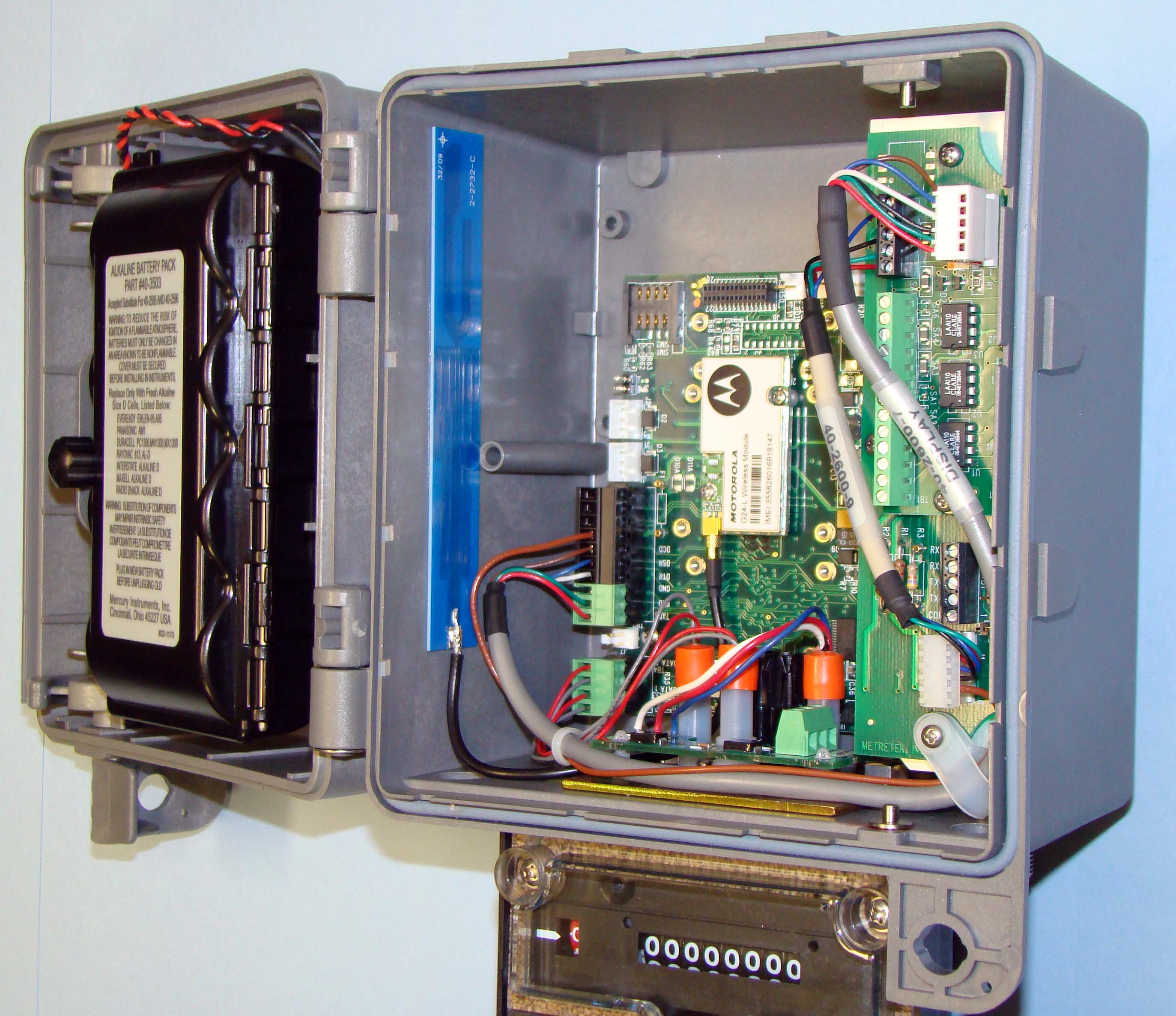
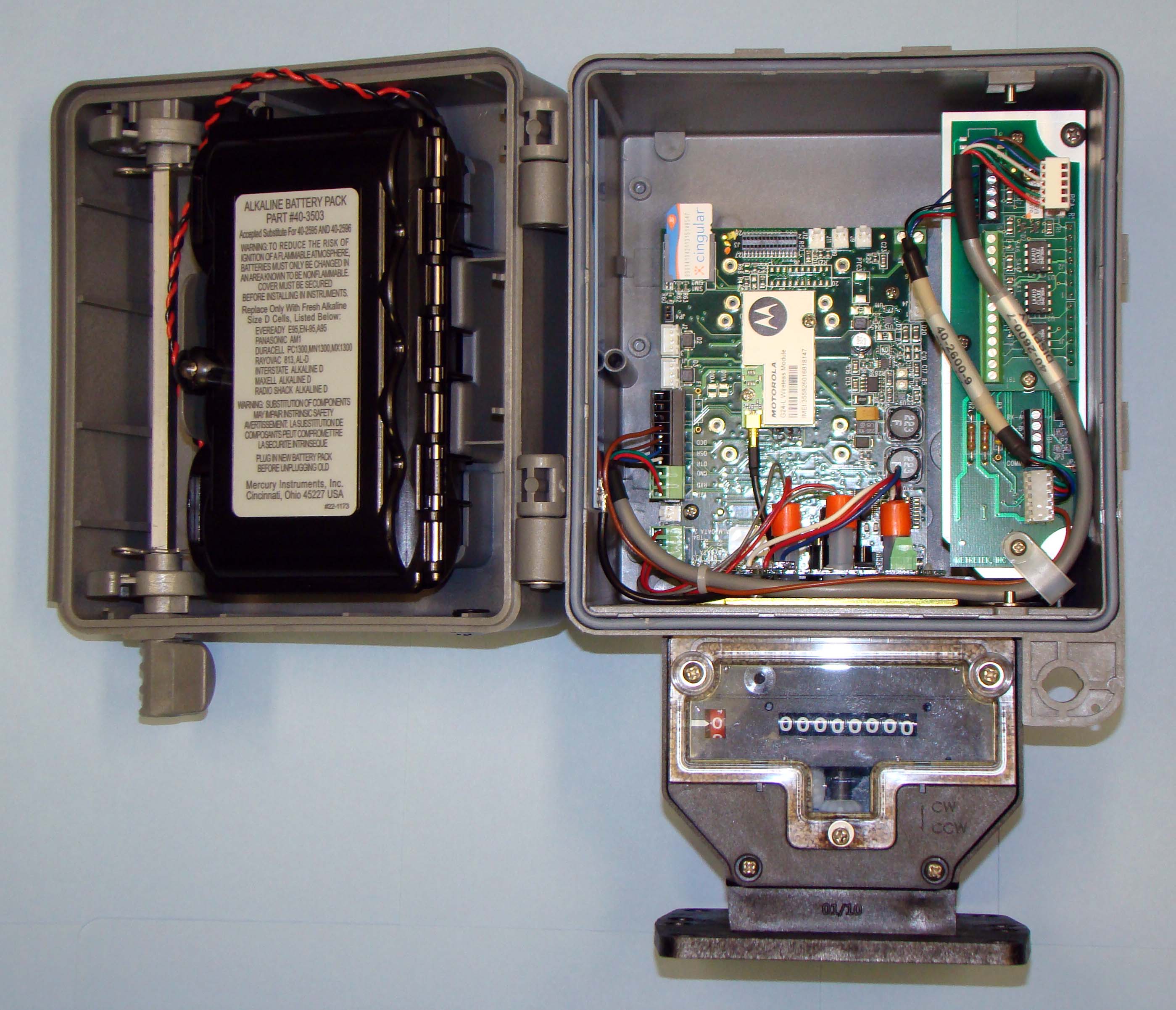
Document Text
Text extracted from the exhibit documents filed with the FCC. Open a document above to read the original.
Users Manual
Cellular Network Interface–2 (CNI2) Operating and Installation Guide Version:1.01 Issued:May 3, 2010 --Preliminary--Not Released--Preliminary--Not Released--Preliminary-- Copyright©2010Honeywell |Mercury Instruments,Cincinnati, Ohio,USA. CNI2Operating and InstallationGuide 1 Contents REVISION HISTORY................................................................................................................10 TRADEMARKS AND COPYRIGHTS.......................................................................................11 SYMBOLS AND ICONS...........................................................................................................12 IMPORTANT BATTERY INFORMATION.................................................................................14 CNI2 OVERVIEW.....................................................................................................................15 CNI2 FEATURES.....................................................................................................................15 CERTIFICATIONS....................................................................................................................15 MECHANICAL ASSEMBLIES..................................................................................................16 INSTRUMENT MOUNTINGOPTIONS...............................................................................................16 WALL MOUNTING............................................................................................................................16 METER INDEX BASE........................................................................................................................17 VERTICAL PIPE MOUNTING............................................................................................................20 ENCLOSURE SEALING....................................................................................................................21 INTERNAL BATTERY POWER OPTIONS.........................................................................................21 INTERNAL CIRCUIT BOARDS..........................................................................................................24 CNI2 Board....................................................................................................................................24 Serial Port Multiplexer Board..........................................................................................................25 RS-485 Serial Data Converter........................................................................................................26 Serial Multiplexer & RS-485 Boards...............................................................................................27 Summary of Serial Data Connection Scenarios..............................................................................28 CNI2 INDEX BASE............................................................................................................................30 OPTIONAL REMOTE PULSE TRANSMITTER..................................................................................33 ANTENNA OPTIONS.........................................................................................................................34 TAMPER DETECT & CALLSWITCH OPTIONS................................................................................36 ELECTRICAL ASSEMBLIES...................................................................................................37 CIRCUIT BOARD CONNECTORS & JUMPERS................................................................................37 Cellular Radio Module....................................................................................................................38 SIM Card Socket............................................................................................................................38 Reset Jumper JP4.........................................................................................................................38 Power Connectors J1 & J2.............................................................................................................38 Terminal Block TB2........................................................................................................................39 Terminal Block TB4........................................................................................................................39 JP3 & JP6 Jumper Settings............................................................................................................39 Connector J4.................................................................................................................................40 Terminal Block TB1........................................................................................................................41 Connector J9.................................................................................................................................41 Connector J11...............................................................................................................................41 Connector J12...............................................................................................................................41 Connector J7.................................................................................................................................42 RS-232 MULTIPLEXER BOARD........................................................................................................43 RS-485 CONVERSION BOARD........................................................................................................45 UNCORRECTED PULSE OUTPUT BOARD......................................................................................46 SIGNAL INPUTS & OUTPUTS...........................................................................................................47 Alar…
Text truncated - open the document above for the full version.
ID Label/Location Info
20-7895 40-5103-X 60-5099 22-2179 22-2156
ID Label/Location Info
DETAIL A SCALE .875 1 1 2 2 3 3 4 4 5 5 6 6 7 7 8 8 AA BB CC DD SCALE MATERIAL ASSEMBLY, CNI2 COMPOSITE D DWG SIZE 22-5555 PROJECT DRAWN BYCHANGE NOTICE DWG. # CN-2642 11/18/2009 BMB DATE B REV. 7 SHT OF 2 THIS DOCUMENT CONTAINS CONFIDENTIAL AND PROPRIETARY INFORMATION OF MERCURY INSTRUMENTS AND NEITHER IT NOR THE INFORMATION CONTAINED THEREIN SHALL BE DISCLOSED TO OTHERS OR DUPLICATED OR USED FOR OTHERS WITHOUT THE EXPRESS WRITTEN CONSENT OF MERCURY INSTRUMENTS FEATURE 50 MOUNTING COATING DIMENSIONS ARE IN INCHES [METRIC mm] BREAK ALL SHARP EDGES UNLESS OTHERWISE SPECIFED TOLERANCES ARE: FRACTIONAL DECIMAL ANGLE PARTS LIST DESCRIPTIONQTY PART NUMBER ASSEMBLY, HOUSING, METER MOUNT 1 22-1090-1 UMB, COMPOSITE 1 22-1164 1/4-20 7/32" SS HEX NUT 260-1607 ASSEMBLY, PLATE, SWITCH MOUNTING 1 22-1494 PLUG, 1/2 NPT 1 20-8312-1 O-RING, .676 ID X .816 OD X .07, NEOPRENE, BLACK, SIZE 017 1 22-1103 JAM NUT, 1/2" NPT 1 22-1102 ASSEMBLY,SOLID DOOR, COMPOSITE CASE 1 22-1186-1 E-RING, EXTERNAL, .25 DIA, SSTL 1 22-1296 ASSY, CNI 2 1 40-5103-X SCREW, 4-20 HIGH-LOW X .25", PHIL, PH HD 360-5099 SERIAL NUMBER LABEL, CNI2 COMPOSITE 1 22-2179 PLUG, 3/16 DIA. 1 20-8718 1 22-FCC-Label PARTS LIST DESCRIPTIONQTY PART NUMBER ASSY, REMOTE CASE, CNI2, W/O SHIELDING 1 22-2131-1 PLUG, 1/2 NPT 220-8312-1 FITTING, STRAIN RELIEF, 1/2 NPT 1 20-8911 PLUG, STRAIN RELIEF 3/8" DIA. 1 20-7552 NUT, 1/2 NPT 320-7895 WASHER, #10 EXTERNAL LOCK 4 20-5300 HANGER, TOP220-1586 HANGER, BOTTOM220-1587 WASHER, FLAT, #10 4 60-5029 SCREW, 10-16 x 3/8" HIGH-LOW PAN HD, PHILLIPS 4 60-5038 ASSEMBLY,SOLID DOOR, COMPOSITE CASE 1 22-1186-1 E-RING, EXTERNAL, .25 DIA, SSTL 1 22-1296 ASSY, CNI 2 1 40-5103-X SCREW, 4-20 HIGH-LOW X .25", PHIL, PH HD 360-5099 LABEL, CSA LISTING, MI WIRELESS, CNI2 1 22-2156 SERIAL NUMBER LABEL, CNI2 COMPOSITE 1 22-2179 A THIS INFORMATION PERTAINS TO ALL MOUNTINGS FEATURE 50 MOUNTING METER MOUNT FEATURE 50 MOUNTING WALL MOUNT 22-1090-1 40-5103-X 60-5099 60-1607 22-1494 22-1103 20-8312-1 22-1102 60-5038 60-5029 20-1586 20-5300 60-5029 20-1587 20-5300 22-2131-1 40-5103-X 60-5099 20-7895 60-5038 20-8312-1 20-8911 20-7552 22-1186-1 22-1296 40-5103-X 60-5099 22-2179 A CHANGED FEATURE NUMBERS AND PAGE LAYOUTS TO MATCH MACOLA CONFIGURATOR BMB 3/5/10 CN-2688 22-1164 B REMOVED AUX COMM BOARDS FROM DRAWING BASED UPON PTCRB APPROVALS BMB 4/5/10 CN-2701 20-8718 NOTES: 1) TORQUE SCREWS TO 6 IN-LBS MAX. NOTES: 1) TORQUE SCREWS TO 6 IN-LBS MAX. APPLY GREASE TO TOP AND BOTTOM CAMS BEFORE CLOSING DOOR. SEE NOTE 1 SEE NOTE 1 SEE NOTE 1 SEE NOTE 1 22-2156
RF Exposure Info
Applicable Documents xG24-L Module Hardware DescriptionNovember 15, 2008 Applicable Documents •G24-L Developer's Kit - 6802984C10 •G24-L AT Commands - 6802983C95 Regulatory Requirements The G24-L module is compliant with applicable FCC, IC and European R&TTE requirements. The integrated system incorporating the G24-L module may be subject to further regulations and standards. Motorola strongly recommends thatthe system integrator seeks professional advice regarding the regulations and standards that apply to their product. The Federal Communications Commission (FCC) requires application for certification of digital devices in accordance with CFR Title 47, Part 2and Part 15. This includes Electromagnetic Energy Exposure (EME) testing. As the G24-L modem is not a standalone transceiver but is an integrated module, the G24-L cannot be tested by itself for EMEcertification. It is, however, the integrators responsibility to have the completed device tested for EME certification. The module is compliant to European R&TTEdirective requirements; however the complete system (host plus G24 module) may be subject toR&TTE or other directives (for instance the EMC directive 2004/108/EC). Motorola stronglyrecommends that the system integrator seek professional advice regarding the applicable standards and directives, and most efficient route to demonstrating compliance, and required product markings. The G24-L module is compliant to FCC, IC and R&TTE requirements allowing use within Europe and North America. Use in other regions may require regional"type approvals" which the manufacturer of the final product integration orreseller will be responsible for procuring. Many regional type approvals are based upon compliance to FCC, R&TTE, ETSI and other standards that the G24-L is compliant with. Itis strongly recommended that professional advice be sought before placing the finished integrated product on the market to establish local approval and marking requirements. Safety Statement and Requirements Certain safety precautions must be observed duringall phases of the operation, usage, service or repair of any cellular terminal or mobile incorporating the G24-L module. The integrator is advised to consider the following general cautions in the context of their integrated system incorporating the G24-L module, and to provide the end user with the applicable warnings and advice of safe operation of the equipment. Failure to comply with these precautions violates safety standards of design, manufacture and intended use of the product. Motorola assumes no liability for customer failure to comply with these precautions. •The G24-L must be operated at the voltages described in the technical documentation •The G24-L must not be mechanically nor electrically changed. Useof connectors should follow the guidance of thetechnical documentation •The G24-L is designed to meet the EMC requirements of EN301 489-1 and EN301 489-7 for R&TTE devices using GSM •When integrating the G24-L into a system, Motorola recommends testing the system to EN301 489-1 and EN301 489-7 for R&TTE devices using GSM •The G24-LC meets the safety requirements of EN60950 Preface November 15, 2008G24-L Module Hardware Descriptionxi •Systems using the G24-L are subject to mandatory EMC testing under directive 2004/108/EC (see item 3 above). Other directives, such as the LVD directive 2006/95/EC, may also apply to a system using the G24-L module •The integrated product incorporating the G24-L moduel must be evaluated for SAR under intended use conditions, and suitable text and SAR values be provided to the end user •No wireless device can guarantee operation at all times due to network or interference conditions, A user should never rely on a wireless device as the sole means of making emergency calls •The G24-L module complies with all applicable standards and directives, this does not guarantee that the product it is integrated intocomplies, expert advice should be sought to identify the applicable regulations and show compliance Suitable warning statements regarding the use of RF energy in the integrated host system should be given in the end user documentation. Antenna and Transmission Safety Precautions User Operation The G24-L module is normally supplied without an antenna, and is compliant with SAR requirements provided the following conditions are observed. Do not operate your unit when a person is within 8 inches (20 centimeters) of the antenna. A person or object within 8 inches(20 centimeters) of the antenna could impair call quality and may cause the phone to operate at a higher power level than necessary. Important:The unit must be installed in a manner that provides a minimum separation distance of 20 cm or more between the antenna and persons and must not be co-located or operate in conjunction with any other antenna or transmitter to satisfy FCC RF exposure requirements for mobile transmitting devices. Important:To comply with the FCC RF exposure limits and satisfy the categorical exclusion requirements for mobile transmitters, the requirements described in the following section,Antenna Installation , must be met. Antenna Installation •The antenna installation must provide a minimum separation distance of 20 cm from users and nearby persons and must not be co-located or operating in conjunction with any other antenna or transmitter. •The combined cable loss and antenna gainmust not exceed +6.8 dBi (850 band). The combined cable loss and antenna gain must notexceed +2.2 dBi and total system output must not exceed 2.0W EIRP in the PCS (1900) band in order to comply with the EIRP limit of 24.232 (b). OEM installers must be provided with antenna installation instruction and transmitter operating conditions for satisfying RF exposure compliance. •For system integrations requiring higher antenna gain, or position closer than 20cm from the body, SAR compliance testing of the completed product will be required. It is strongly recommended…
Text truncated - open the document above for the full version.
RF Exposure Info
Applicable Documents xG24-L Module Hardware DescriptionNovember 15, 2008 Applicable Documents •G24-L Developer's Kit - 6802984C10 •G24-L AT Commands - 6802983C95 Regulatory Requirements The G24-L module is compliant with applicable FCC, IC and European R&TTE requirements. The integrated system incorporating the G24-L module may be subject to further regulations and standards. Motorola strongly recommends thatthe system integrator seeks professional advice regarding the regulations and standards that apply to their product. The Federal Communications Commission (FCC) requires application for certification of digital devices in accordance with CFR Title 47, Part 2and Part 15. This includes Electromagnetic Energy Exposure (EME) testing. As the G24-L modem is not a standalone transceiver but is an integrated module, the G24-L cannot be tested by itself for EMEcertification. It is, however, the integrators responsibility to have the completed device tested for EME certification. The module is compliant to European R&TTEdirective requirements; however the complete system (host plus G24 module) may be subject toR&TTE or other directives (for instance the EMC directive 2004/108/EC). Motorola stronglyrecommends that the system integrator seek professional advice regarding the applicable standards and directives, and most efficient route to demonstrating compliance, and required product markings. The G24-L module is compliant to FCC, IC and R&TTE requirements allowing use within Europe and North America. Use in other regions may require regional"type approvals" which the manufacturer of the final product integration orreseller will be responsible for procuring. Many regional type approvals are based upon compliance to FCC, R&TTE, ETSI and other standards that the G24-L is compliant with. Itis strongly recommended that professional advice be sought before placing the finished integrated product on the market to establish local approval and marking requirements. Safety Statement and Requirements Certain safety precautions must be observed duringall phases of the operation, usage, service or repair of any cellular terminal or mobile incorporating the G24-L module. The integrator is advised to consider the following general cautions in the context of their integrated system incorporating the G24-L module, and to provide the end user with the applicable warnings and advice of safe operation of the equipment. Failure to comply with these precautions violates safety standards of design, manufacture and intended use of the product. Motorola assumes no liability for customer failure to comply with these precautions. •The G24-L must be operated at the voltages described in the technical documentation •The G24-L must not be mechanically nor electrically changed. Useof connectors should follow the guidance of thetechnical documentation •The G24-L is designed to meet the EMC requirements of EN301 489-1 and EN301 489-7 for R&TTE devices using GSM •When integrating the G24-L into a system, Motorola recommends testing the system to EN301 489-1 and EN301 489-7 for R&TTE devices using GSM •The G24-LC meets the safety requirements of EN60950 Preface November 15, 2008G24-L Module Hardware Descriptionxi •Systems using the G24-L are subject to mandatory EMC testing under directive 2004/108/EC (see item 3 above). Other directives, such as the LVD directive 2006/95/EC, may also apply to a system using the G24-L module •The integrated product incorporating the G24-L moduel must be evaluated for SAR under intended use conditions, and suitable text and SAR values be provided to the end user •No wireless device can guarantee operation at all times due to network or interference conditions, A user should never rely on a wireless device as the sole means of making emergency calls •The G24-L module complies with all applicable standards and directives, this does not guarantee that the product it is integrated intocomplies, expert advice should be sought to identify the applicable regulations and show compliance Suitable warning statements regarding the use of RF energy in the integrated host system should be given in the end user documentation. Antenna and Transmission Safety Precautions User Operation The G24-L module is normally supplied without an antenna, and is compliant with SAR requirements provided the following conditions are observed. Do not operate your unit when a person is within 8 inches (20 centimeters) of the antenna. A person or object within 8 inches(20 centimeters) of the antenna could impair call quality and may cause the phone to operate at a higher power level than necessary. Important:The unit must be installed in a manner that provides a minimum separation distance of 20 cm or more between the antenna and persons and must not be co-located or operate in conjunction with any other antenna or transmitter to satisfy FCC RF exposure requirements for mobile transmitting devices. Important:To comply with the FCC RF exposure limits and satisfy the categorical exclusion requirements for mobile transmitters, the requirements described in the following section,Antenna Installation , must be met. Antenna Installation •The antenna installation must provide a minimum separation distance of 20 cm from users and nearby persons and must not be co-located or operating in conjunction with any other antenna or transmitter. •The combined cable loss and antenna gainmust not exceed +6.8 dBi (850 band). The combined cable loss and antenna gain must notexceed +2.2 dBi and total system output must not exceed 2.0W EIRP in the PCS (1900) band in order to comply with the EIRP limit of 24.232 (b). OEM installers must be provided with antenna installation instruction and transmitter operating conditions for satisfying RF exposure compliance. •For system integrations requiring higher antenna gain, or position closer than 20cm from the body, SAR compliance testing of the completed product will be required. It is strongly recommended…
Text truncated - open the document above for the full version.
Test Report
Client: Product Designation: CN 12 Report Number: 100101158ATL-001 All services undertaken are subject to the following general policy: This report is for the exclusive use of Intertek's Client and is provided pursuant to the agreement between Intertek and its Client. Intertek's responsibility and liability are limited to the terms and conditions of the agreement. Intertek assumes no liability to any party, other than to the Client in accordance with the agreement, for any loss, expense or damage occasioned by the use of this report. Only the Client is authorized to copy or distribute this report and then only in its entirety. Any use of the Intertek name or one of its marks for the sale or advertisement of the tested material, product or service must first be approved in writing by Intertek. The observations and test results in this report are relevant only to the sample tested. This report by itself does not imply that the material, product, or service is or has ever been under an Intertek certification program. This report must not be used to claim product endorsement by A2LA, NIST, or any agency of the US Government. Tested by: Tests performed by:Report reviewed by: Standard: Larry E. Miller EMC Project Engineer Troy J. Ihle EMC Project Engineer Mercur y Instruments 305A East Drive Melbourne, FL 32904 Contact: Lawrence Sabec Phone: 321.259.9700 Fax: 321.259.2900 TEST REPORT May 11, 2010 Intertek Testing Services NA Inc. 1950 Evergreen Blvd., Suite 100 Duluth, GA 30096 CFR, Title 47, Chapter I, Part 15 Subpart B (USA) ICES-003,Issue 4, 2004 (Canada) Page 1 of 15EMC Report for Mercury Instruments on the CN 12 05/11/2010Report Number: 100101158ATL-001Issued: Intertek 2.0 Test Summary 1.0 Introduction and Conclusion Test DateTest Full NameResultSection System setup including cable interconnection details, support equipment and simplified block diagram. (System Setup)4.0 05/03/2010Radiated emissions (E-field) GSM Cellular radio - G24L (Radiated Emissions)PASS5.0 05/03/2010Radiated emissions (E-field) CDMA cellular radio - C24 (Radiated Emissions)PASS6.0 The tests indicated in section 2.0 were performed on the product constructed as described in section 3.0. The remaining test sections are the verbatum text from the actual data sheets used during the investigation. These test sections include the test name, the specified test Method, a list of the actual Test Equipment Used, documentation Photos, Results and raw Data. No additions, deviations, or exclusions have been made from the standard(s) unless specifically noted. Based on the results of our investigation, we have concluded the product tested complies with the requirements of the standard(s) indicated. The results obtained in this test report pertain only to the item(s) tested. Page 2 of 15EMC Report for Mercury Instruments on the CN 12 05/11/2010Report Number: 100101158ATL-001Issued: Intertek 3.0 Description of Equipment Under Test Equipment Under Test Description Manufacturer Mode l Number Serial Number Data Logger (pulse accumulator) Mercury Instruments, Inc. CN12, w/GSM Radio-G24L IMEI: 355826016819228 Data Logger (pulse accumulator) Mercury Instruments, Inc. CN12, w/ CDMA Radio-C24 MEID: A0000002FF7274 EUT receive date: 5/3/2010 EUT receive condition: Good Description of EUT provided by Client: The CN12 product consists of a main circuit board with cellar radio housed in an enclosure and can be powered from a variet y of power sources. It serves as a data logger (pulse accumulator) and a cellular modem for the natural gas industry. Either a Motorola GSM cellular radio (model G24L) or Motorola CDMA cellular radio (model C24) is supplied with the product. The product also has several optional communications bo ards that allow the custo mer to connect external equipment to the unit. A universal mounting base (UMB index) allows the unit to mount directly to a natural gas pipeline and measure gas flow. Description of EUT exercising: EUT was powered at 6Vdc (four D batteries), once powered the CN12 was placed into a test mode. This test mode places the CN12 board into a fully awake operating mo de wit h the serial port active and the cellular radio in the receive mode. Page 3 of 15EMC Report for Mercury Instruments on the CN 12 05/11/2010Report Number: 100101158ATL-001Issued: Intertek System setup including cable interconnection details, support equipment and simplified block diagram. (System Setup) 4.0 Method: Record the details of EUTcabling, document the support equipment, and show the interconnections in a block diagram. EUT PC A Simplified block diagram Drawing: Page 4 of 15EMC Report for Mercury Instruments on the CN 12 05/11/2010Report Number: 100101158ATL-001Issued: Intertek System setup including cable interconnection details, support equipment and simplified block diagram. (System Setup) 4.0 A Description EUT Cabling Connection Length Shielding FerritesIDFromTo EUT PCSerial Cable7myesnone Support Equipment DescriptionManufacturerModel NumberSerial Number PCDellLatitude D610 (PP11L)OU8082-48643-SAP-0878 Data: Page 5 of 15EMC Report for Mercury Instruments on the CN 12 05/11/2010Report Number: 100101158ATL-001Issued: Intertek Radiated emissions (E-field) GSM Cellular radio - G24L (Radiated Emissions)5.0 Method: Measurements in the frequency range of 30 MHz to 1000 MHz shall be performed with a quasi-peak detector instrument that meets the requirements of Section One of CISPR 16. Above 1000 MHz, a peak detector shall be used. Peak values converted to average by appying the duty cycle correction factor, when applicable. When an average detector is used, it shall meet the requirements of Section One of CISPR 16. The measuring antenna shall correlate to a balanced dipole. Bandwidths: 30 MHz to 1000 MHz: 120 kHz RBW and 1 MHz VBW Above 1000 MHz: 1 MHz RBW and 3 MHz VBW Measurements of the radiated field are made with the antenna located at a distance of 3 or 10 meters from the EUT. The limit applied to the measurement shall be appro…
Text truncated - open the document above for the full version.
Test Setup Photos
ÎÒÔÔÒÓÔŒª∞±Æ ̈ “ ́≥æªÆÊ ÔÔÔÔÎËflÑÛÔ◊≠≠ ́ªºÊ ◊≤ ̈ªÆ ̈ªμ Œøº∑ø ̈ªºª≥∑≠≠∑±≤≠ ̄¤Û∫∑ª¥º ̃ŸÕ”›ª¥¥ ́¥øÆÆøº∑±ÛŸÓÏ‘ ̄Œøº∑ø ̈ªº¤≥∑≠≠∑±≤≠ ̃ÎÚ Õª ̈ ́∞ ⁄Ʊ≤ ̈ ∑ª© –∏± ̈±Ê –øπª È ±∫ ÔΤ”› Œª∞±Æ ̈ ∫±Æ ”ªÆΩ ́Æß ◊≤≠ ̈Æ ́≥ª≤ ̈≠ ±≤ ̈∏ª ›“ ÔÓ ÎÒÔÔÒÓÔŒª∞±Æ ̈ “ ́≥æªÆÊ ÔÔÔÔÎËflÑÛÔ◊≠≠ ́ªºÊ ◊≤ ̈ªÆ ̈ªμ Œøº∑ø ̈ªºª≥∑≠≠∑±≤≠ ̄¤Û∫∑ª¥º ̃ŸÕ”›ª¥¥ ́¥øÆÆøº∑±ÛŸÓÏ‘ ̄Œøº∑ø ̈ªº¤≥∑≠≠∑±≤≠ ̃ÎÚ Õª ̈ ́∞ ŒªøÆ ∑ª© –∏± ̈±Ê –øπª Ë ±∫ ÔΤ”› Œª∞±Æ ̈ ∫±Æ ”ªÆΩ ́Æß ◊≤≠ ̈Æ ́≥ª≤ ̈≠ ±≤ ̈∏ª ›“ ÔÓ ÎÒÔÔÒÓÔŒª∞±Æ ̈ “ ́≥æªÆÊ ÔÔÔÔÎËflÑÛÔ◊≠≠ ́ªºÊ ◊≤ ̈ªÆ ̈ªμ Œøº∑ø ̈ªºª≥∑≠≠∑±≤≠ ̄¤Û∫∑ª¥º ̃›‹”flΩª¥¥ ́¥øÆÆøº∑±Û›ÓÏ ̄Œøº∑ø ̈ªº¤≥∑≠≠∑±≤≠ ̃ÍÚ Õª ̈ ́∞ ⁄Ʊ≤ ̈ ∑ª© –∏± ̈±Ê –øπª ÔÓ ±∫ ÔΤ”› Œª∞±Æ ̈ ∫±Æ ”ªÆΩ ́Æß ◊≤≠ ̈Æ ́≥ª≤ ̈≠ ±≤ ̈∏ª ›“ ÔÓ ÎÒÔÔÒÓÔŒª∞±Æ ̈ “ ́≥æªÆÊ ÔÔÔÔÎËflÑÛÔ◊≠≠ ́ªºÊ ◊≤ ̈ªÆ ̈ªμ Œøº∑ø ̈ªºª≥∑≠≠∑±≤≠ ̄¤Û∫∑ª¥º ̃›‹”flΩª¥¥ ́¥øÆÆøº∑±Û›ÓÏ ̄Œøº∑ø ̈ªº¤≥∑≠≠∑±≤≠ ̃ÍÚ Õª ̈ ́∞ ŒªøÆ ∑ª© –∏± ̈±Ê –øπª ÔÌ ±∫ ÔΤ”› Œª∞±Æ ̈ ∫±Æ ”ªÆΩ ́Æß ◊≤≠ ̈Æ ́≥ª≤ ̈≠ ±≤ ̈∏ª ›“ ÔÓ
Contact Information
Applicant
Lawrence M Sabec(Mechanical Designer)
Technical Contact
Mercury Instruments LLCLawrence M Sabec
[email protected]513-272-1111
305A East Drive · Melbourne, Florida · United States
Non-Technical Contact
Mercury Instruments LLCSteven R Snoke
[email protected]513-272-1111
Test Firm
Intertek Testing Services NA Inc.Charles Parker
Technical Specifications
| # | Rule Parts | Frequency Range | Power Output |
|---|---|---|---|
| 1 | 15B | 824.2 MHz - 848.8 MHz | - |