YJFV2CRTLGarage Door Smart Control (Controller)
GUARDIAN SHANGHAI CORP.
Click to zoom
Application Details
- Equipment Class
- DTS - Digital Transmission System
- Date of Grant
- Mar 15, 2021
- Application Purpose
- Original Equipment
- Date of Application
- Mar 15, 2021
- Equipment Note
- Garage Door Smart Control (Controller)
- Frequency Range
- 2402.00000000 - 2480.00000000
- Company
- GUARDIAN SHANGHAI CORP.
- Country
- China
Documents & Files
Document Text
Text extracted from the exhibit documents filed with the FCC. Open a document above to read the original.
Users Manual
Smart Control Kit Installation Guide adhguardianusa.com 1-424-272-6998 TM Model V2 Installation requires no special tools—you’ll just need a screwdriver, stepladder and smartphone! ControllerPower adapter Wireless door sensor Opener cable Thank you for purchasing the beam Smart Control Kit! Please read and follow all installation instructions. Homeowners should retain this guide for reference. TIP: If you are a professional installer, setup within the beam Home app should be done using the homeowner’s smartphone. Date Installed: ______________________ Download the app & begin setup • While inside your home, download the “beam Home” app from the App Store (iOS) or Google Play (Android). • Open the app, and select “Setup Your beam.” • Follow prompts within the app to verify the WiFi network you’d like your controller to connect to, and enter your network password. TIP: Make sure you do not select a 5G network for setup (beam only connects to 2.4GHz networks). 1 Bottom Side Power up the controller • Locate the controller and power adapter. Plug the adapter into the DC IN port on the controller and a nearby power source. • The controller’s WiFi status light will blink orange to indicate it’s ready for setup. 2 Setup Port Top Side Power Indicator WiFi Status 3 Program the controller • Follow prompts within the app, and when directed, press your phone screen tightly against the bottom setup port. TIP: It may be helpful to dim the lights or cup your hand over your phone during programming to minimize light interference. • If successful, the controller will beep and the WiFi status light will blink green. You’ll then be prompted to create an account. (If not successful, the WiFi status light will blink red and you will be guided through setup again.) Point screen at sensor now! 5 Scan the wireless door sensor code • Locate the wireless door sensor and follow prompts within the app to scan the code (found on the back of the sensor). • Enter a name to identify your door. • Unplug the controller and head out to the garage! 4 Mount the wireless door sensor • Clean and wipe dry an area at the top of your garage door’s interior panel. • Remove the battery tab from the back of the wireless door sensor and mount to the cleaned area of the garage door using the adhesive Velcro strip. 5 Mounting location (top of interior panel) Mount the controller • Locate the controller and power adapter, and grab your stepladder. • Clean and wipe dry your selected mounting location, either on the garage door opener or a nearby surface. Mount using the adhesive strip on the back of the controller. TIP: The controller should be mounted within 3 feet of the garage door opener and within 6 feet of a power source. 6 Mounting location options Connect the opener cable to the controller • Locate the opener cable . • Plug the black connector into the opener port on the top side of the controller. 7 WiFi Status Power Indicator DC IN Port Opener Port • Unplug your garage door opener. • Using a small screwdriver, connect the other end of the opener cable to your garage door opener push button terminals. If there are already other wires present, they can be spliced together with the opener cable to share the same terminals. 8 TIP: View sample connection diagrams for other garage door opener makes and models at: adhguardianusa.com/install-beam Connect the controller to the garage door opener PUSH BUTTONPUSH BUTTONPUSH BUTTONPUSH BUTTONPUSH BUTTON Sample diagram of Guardian terminals Power up the controller & opener • Plug the power adapter into the DC IN port on the controller and a nearby power source. •Plug your garage door opener back in. All done! 9 Get the most from your beam Smart Control Kit! • Share access with others – Invite friends and family within the app. No need to share your code or buy additional remotes. • Explore integrations – beam plays well with others, from IFTTT to Amazon Alexa. • Register your Smart Control Kit – Register online at: adhguardianusa.com/warranty-information ©2019, ADH Guardian USA LLC. Amazon, Alexa and all related logos are trademarks of Amazon.com, Inc. or its affiliates. Guardian Access & Door Hardware I 122 Penn Street I El Segundo, CA 90245 Warning: To reduce the risk of injury to persons: • Use this Smart C ontrol Kit only with Residential Sectional Garage doors. • Do not enable this device on a one-piece or swinging garage door. • Do not use this device on garage door openers made before 1993 without a working photo-eye safety system. FCC Statement: Any Changes or modifications not expressly approved by the party responsible for compliance could void the user’s authority to operate the equipment. This device complies with part 15 of the FCC Rules. Operation is subject to the following two conditions: (1) This device may not cause harmful interference,and (2) this device must accept any interference received, including interference that may cause undesired operation. FCC Radiation Exposure Statement: This equipment complies with FCC radiation exposure limits set forth for an uncontrolled environment .This equipment should be installed and operated with minimum distance 20cm between the radiator& your body. Note: This equipment has been tested and found to comply with the limits for a Class B digital device, pursuant to part 15 of the FCC Rules. These limits are designed to provide reasonable protection against harmful interference in a residential installation. This equipment generates uses and can radiate radio frequency energy and, if not installed and used in accordance with the instructions, may cause harmful interference to radio communications. However,there is no guarantee that interference will not occur in a particular installation. If this equipment does cause harmful interference to radio or television reception, which can be determined by turning the equipment off and on, the user is encouraged to try to correct the interference by one or more of the following measures: —Reor…
Text truncated - open the document above for the full version.
Attestation Statements
Company: Guardian Shanghai Corp. Add: 368, Min Shen Rd, SongJiang, Shanghai, China Tel: 57684828Fax: 57685151 Date: 2021-02-20 Attestation Letter Dear Sir or Madam: The chip nRF52832 installed in our product Garage Door Smart Control (model name: V2(controller), FCC ID: YJFV2CRTL), which support BLE, ANT+ and 2.4G SRD. But, for the product, it only activates BLE function, the other functions are disabled by using the software. Please contact me if there is need for any additional clarification or information. Best Regards, Sincerely Yours, Signature: Typed or Printed Name: Vincent Chan Title: PM FE DERAL COMM UNICATIONS COMMISSION Authorization and Evaluation Division 7435 Oakland Mills Road Columbia, MD 21046
Cover Letter(s)
Company Name: GUARDIAN SHANGHAI CORP. Add: 368, Min Shen Rd, SongJiang, Shanghai, China Tel: +86-21-57684828 Fax: +86-21-57685151 E-mail: [email protected] FCC Confidential Authorization Date:2019-09-12 FEDERAL COMMUNICATIONS COMMISSIONS Authorization and Evaluation Division 74 35 Oakland Mills Road Columbia, MD 21 046 Subject: Confidentiality Request regarding application for certificatio n of FCC ID: YJFV2CRTL To: whom it may concern, In accord ance with Sections 0.457 and 0.459 of the Commission’s Rules, GUARDIAN SHANGHAI CORP. hereby requests long-term confidential treatment of information accompanying this application as outlined below: Block Diagram Schematics Operation Description The above materials contain proprietary and confidential information not customarily released to the public. The public disclosure of these materials provides unjustified benefits to its competitors in the market. Sincerely Yours, Signature: Typed or Printed Name: Vincent Chan Title: PM
External Photos
EXHIBIT A - EUT EXTERNAL PHOTOGRAPHS
ID Label/Location Info
50mm 10mm GUARDIAN SHANGHAI CORP. Mo del:V2(controller) FCC ID: YJFV2CRTL
Internal Photos
EXHIBIT B - EUT INTERNAL PHOTOGRAPHS Wi-Fi Antenna BLE Antenna
RF Exposure Info
Bay Area Compliance Laboratories Corp. (Kunshan) Report No.: RSHD190912005-00B FCC Part 15.247 Page 15 of 93 FCC §15.247 (i) & §1.1310 & §2.1091 - MAXIMUM PERMISSIBLE EXPOSURE (MPE) Applicable Standard According to subpart 15.247 (i) and subpart 1.1310, 2.1091 systems operating under the provisions of this section shall be operated in a manner that ensures the public is not exposed to RF energy level in excess of the communication guidelines. Limits for General Population/Uncontrolled Exposure Frequency Range (MHz) Electric Field Strength (V/m) Magnetic Field Strength (A/m) Power Density (mW/cm 2 ) Averaging Time (minutes) 0.3-1.34 614 1.63 *(100) 30 1.34-30 824/f 2.19/f *(180/f²) 30 30-300 27.5 0.073 0.2 30 300-1500 / f/1500 30 1500-100,000 / 1.0 30 f = frequency in MHz; * = Plane-wave equivalent power density Calculated Formulary: Predication of MPE limit at a given distance S = PG/4πR² = power density (in appropriate units, e.g. mW/cm 2 ); P = power input to the antenna (in appropriate units, e.g., mW); G = power gain of the antenna in the direction of interest relative to an isotropic radiator, the power gain factor, is normally numeric gain; R = distance to the center of radiation of the antenna (appropriate units, e.g., cm); Calculated Data: 2.4G Wi-Fi & BLE: Mode Frequency Range (MHz) Maximum Antenna Gain Tune-up Conducted Power Evaluation Distance (cm) Power Density (mW/cm 2 ) MPE Limit (mW/cm 2 ) (dBi) (numeric) (dBm) (mW) 802.11b 2412-2462 2.4 1.74 19.50 89.13 20 0.0308 1.0 802.11g 2.4 1.74 20.50 112.20 20 0.0388 1.0 802.11n- HT20 2.4 1.74 19.00 79.43 20 0.0275 1.0 BLE(1Mbps) 2402-2480 4.0 2.51 0.50 1.12 20 0.0006 1.0 BLE(2Mbps) 2402-2480 4.0 2.51 0.00 1.00 20 0.0005 1.0 Note: 1. For the above tune up power were declared by the manufacturer. 2. Wi-Fi and BLE can't transmit simultaneously. Result: The device meet FCC MPE at 20 cm distance.
Test Report
FCC PART 15.247 TEST REPORT For GUARDIAN SHANGHAI CORP. 368, Min Shen Rd, SongJiang, Shanghai, China FCC ID: YJFV2CRTL Report Type: Original Report Product Type: Garage Door Smart Control Test Engineer: Tyrone Wang Re port Number: RSHD190912005-00B Re port Date: 2021-01-28 Reviewed B y: Oscar Ye EMC Manager Prepared By: Bay Area Compliance Laboratories Corp. (Kunshan) No.248 Chenghu Road, Kunshan, Jiangsu province, China Tel: +86-0512-86175000 Fax: +86-0512-88934268 www.baclcorp.com.cn Bay Area Compliance Laboratories Corp. (Kunshan) Report No.: RSHD190912005-00B FCC Part 15.247 Page 2 of 93 TABLE OF CONTENTS GENERAL INFORMATION ....................................................................................................................................... 4 PRODUCT DESCRIPTION FOR EQUIPMENT UNDER TEST (EUT) ..................................................................................... 4 OBJECTIVE ................................................................................................................................................................... 4 RELATED SUBMITTAL(S)/GRANT(S) ............................................................................................................................. 4 TEST METHODOLOGY .................................................................................................................................................. 5 MEASUREMENT UNCERTAINTY .................................................................................................................................... 5 TEST FACILITY ............................................................................................................................................................. 5 SYSTEM TEST CONFIGURATION .......................................................................................................................... 6 DESCRIPTION OF TEST CONFIGURATION ...................................................................................................................... 6 EQUIPMENT MODIFICATIONS ....................................................................................................................................... 6 EUT EXERCISE SOFTWARE .......................................................................................................................................... 7 SUPPORT EQUIPMENT LIST AND DETAILS .................................................................................................................. 10 EXTERNAL I/O CABLE ................................................................................................................................................ 10 BLOCK DIAGRAM OF TEST SETUP .............................................................................................................................. 10 SUMMARY OF TEST RESULTS ............................................................................................................................. 12 TEST EQUIPMENT LIST ......................................................................................................................................... 13 FCC §15.247 (i) & §1.1310 & §2.1091 - MAXIMUM PERMISSIBLE EXPOSURE (MPE) ................................ 15 FCC §15.203 - ANTENNA REQUIREMENT ........................................................................................................... 16 APPLICABLE STANDARD ............................................................................................................................................ 16 ANTENNA CONNECTOR CONSTRUCTION .................................................................................................................... 16 FCC §15.207 (a) – AC LINE CONDUCTED EMISSIONS ..................................................................................... 17 APPLICABLE STANDARD ............................................................................................................................................ 17 EUT SETUP ................................................................................................................................................................ 17 EMI TEST RECEIVER SETUP ....................................................................................................................................... 17 TEST PROCEDURE ...................................................................................................................................................... 18 FACTOR & OVER LIMIT CALCULATION ...................................................................................................................... 18 TEST RESULTS SUMMARY .......................................................................................................................................... 18 TEST DATA ................................................................................................................................................................ 18 FCC §15.209, §15.205 & §15.247(d) - SPURIOUS EMISSIONS ............................................................................. 25 APPLICABLE STANDARD ............................................................................................................................................ 25 EUT SETUP ................................................................................................................................................................ 25 EMI TEST RECEIVER SETUP ....................................................................................................................................... 26 TEST PROCEDURE ...................................................................................................................................................... 26 TEST RESULTS SUMMARY ..........................................................................................................................................…
Text truncated - open the document above for the full version.
Test Setup Photos
EXHIBIT C - TEST SETUP PHOTOGRAPHS Conducted Emissions (Front View) Conducted Emissions (Left View) Radiated Emissions (Below 1 GHz) Radiated Emissions (Above 1 GHz)
Contact Information
Applicant
Vincent Chan(PM)
Test Firm
Bay Area Compliance Laboratories Corp. (Kunshan)Mr. John Chan
[email protected]+86 0512 86175000
Technical Specifications
| # | Rule Parts | Frequency Range | Power Output |
|---|---|---|---|
| 1 | 15C | 2.40 GHz - 2.48 GHz | 1.00 mW |
Other Applications from GUARDIAN SHANGHAI CORP.
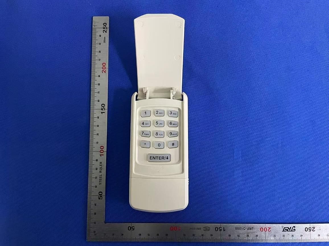
YJFUWK
Dec 18, 2025Universal Keypad
Equipment Class
DSC - Part 15 Security/Remote Control Transmitter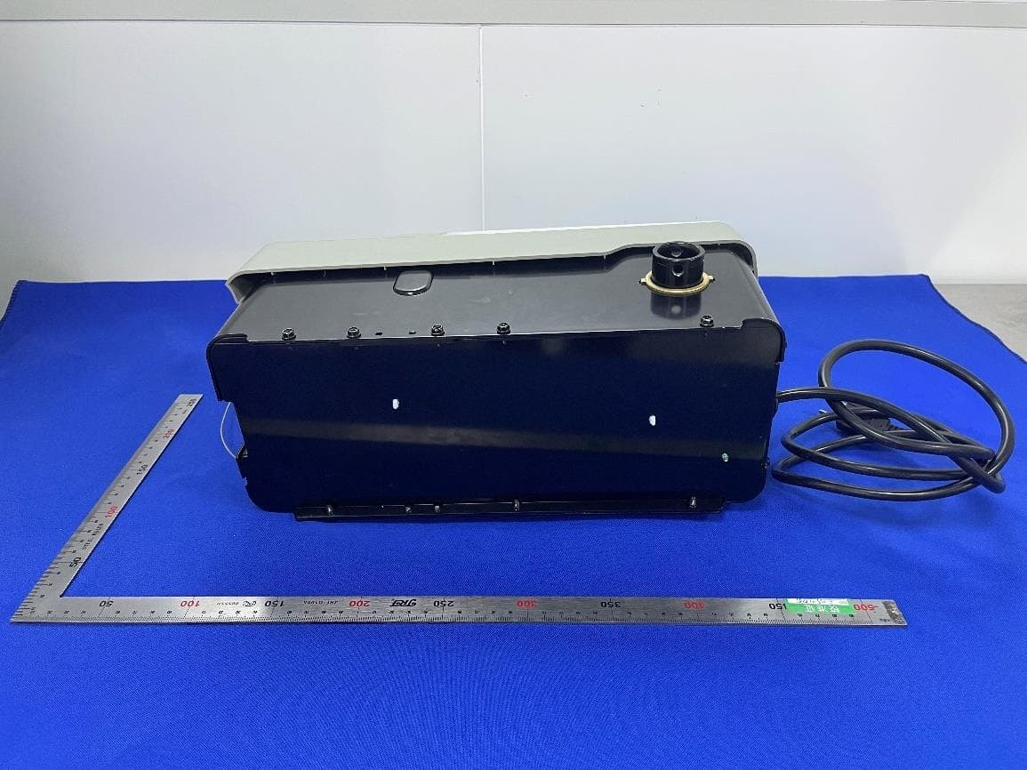
YJFV3
Apr 17, 2023Smart control device for Garage Door Opener
Equipment Class
DTS - Digital Transmission System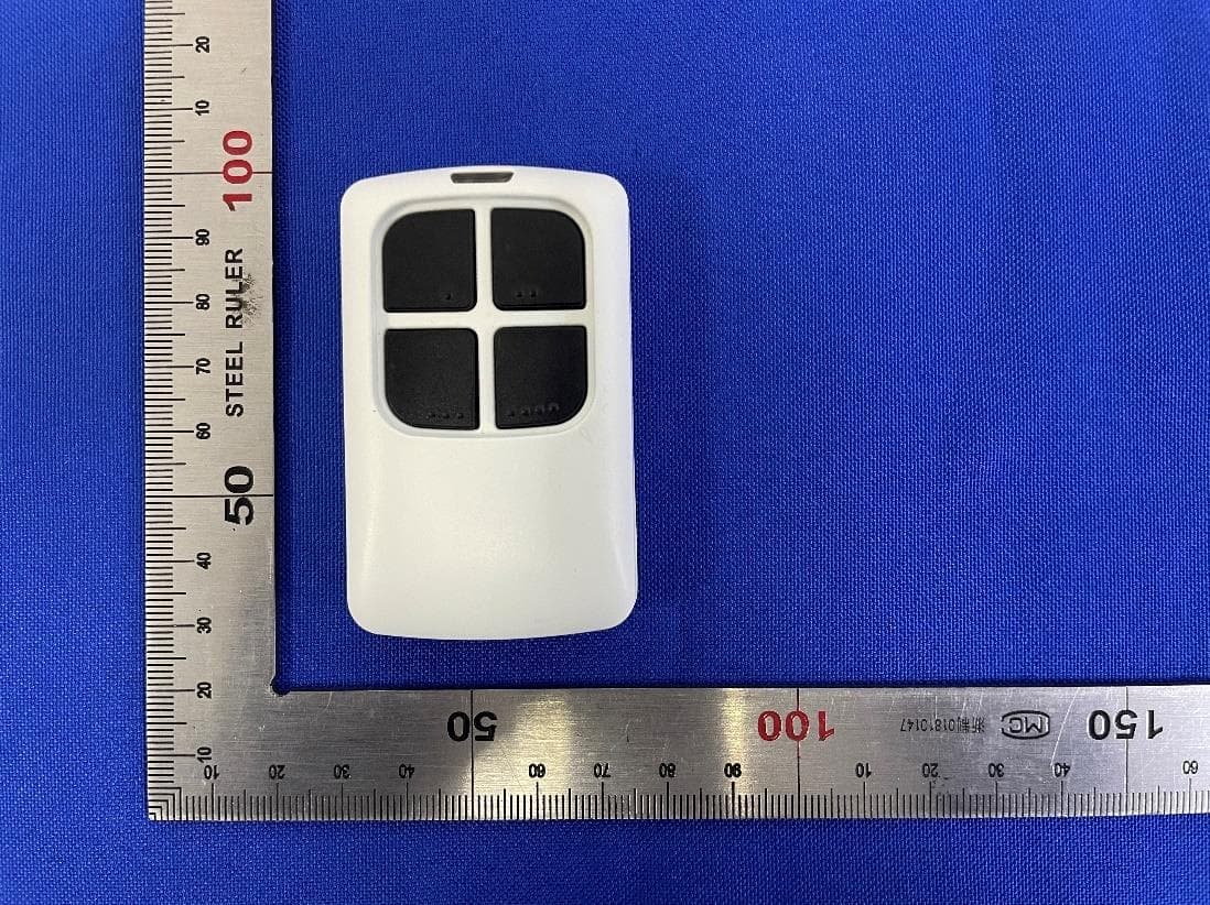
YJFUTX
Apr 16, 2023Remote Control for Garage Door Opener
Equipment Class
DSC - Part 15 Security/Remote Control Transmitter
YJFWK303
Sep 21, 2022Wireless Keyless Entry Pad for Garage Door Opener
Equipment Class
DSC - Part 15 Security/Remote Control Transmitter
YJFV2SEN
Mar 15, 2021Garage Door Smart Control (Sensor)
Equipment Class
DTS - Digital Transmission System