FCCID.CO- FCC ID Database
HomeCompaniesEquipment ClassesSearch

© 2026 FCC ID Database. All rights reserved.

AboutContactData sourced from FCC public records
  1. Home/
  2. Alken, Inc dba Polhemus/
  3. YJUG4HUB01

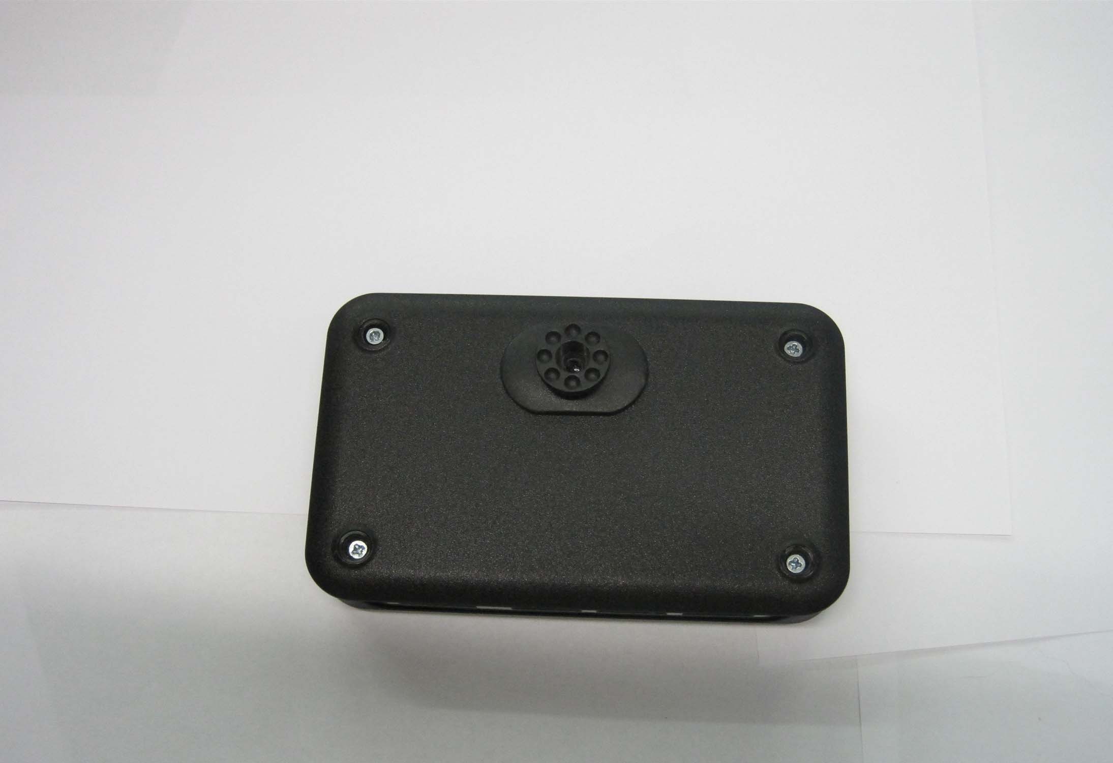
YJUG4HUB01Electromagnetic Tracker

Alken, Inc dba Polhemus
Electromagnetic Tracker - FCC ID YJUG4HUB01 - Alken, Inc dba Polhemus
Click to zoom

Application Details

Equipment Class
DSS - Part 15 Spread Spectrum Transmitter
Date of Grant
Jan 03, 2011
Application Purpose
Original Equipment
Date of Application
Jan 03, 2011
Equipment Note
Electromagnetic Tracker
Frequency Range
2403.75000000 - 2480.25000000
Company
Alken, Inc dba Polhemus
Country
United States

Documents & Files

Select a file to view
Users Manual

↗

Cover Letter(s)

↗
↗

External Photos

↗

ID Label/Location Info

↗
↗

Internal Photos

↗

Test Report

↗

Test Setup Photos

↗

Document Text

Text extracted from the exhibit documents filed with the FCC. Open a document above to read the original.

Users Manual

G 4 Radio Installation Manual Polhemus 40 Hercules Drive PO Box 560 Colchester, VT 05446-0560 Tel: 802-655-3159 Fax: 802-655-1439 URM10PH234 REV A AUG 2010 URM10PH234 REV AAUG 20101 Introduction The G4 radio linkis a2.4 GHzSpread Spectrumsystemconsisting of one or moredata collecting HUBdevices that each have their own RF transceiver moduleand acommon USB dongleradio modulethat attaches to a host computer.The user can use Polhemus provided software to operate the system or develop their own custom software applications using Polhemus provided SDK for Windows or LINUX.A simple block diagram of the system is shown below. The user is requiredto do a one time set-up to associatetheUSBdongle with the HUB devices. Once that is done the system connects automatically and there is no need for user interventionto operate the RF system. Host Computer G4 HUB Magnetic Sensors G4 system RF Module USB Dongle 2.4 GHz RF link RF Module G4 HUB Magnetic Sensors RF Module URM10PH234 REV AAUG 20102 Preparing the system To prepare the system you will need the Hubor Hubs, the USB dongle and a USB cable (provided with the system). You must also have a host computer available with the configuration software provided on the CD that came with the G4 system loaded on the host computer.When you place the CD in the host computer the installation program will automatically run. Followthe instructions to load all the required software components. The diagram below shows the connection ports, switch and LED indicators onthe Hub. All that is required for the RF setup is a USB cable. There is no need to have any sensors plugged infor the initial setup. The battery in the hub is charged via the USB cable so allow at least 30 minutes of charging time to ensure you can complete the set-up and test the system before needing to charge the battery again.The G4 Hubhad 3 sensor ports for connectingmagnetic sensing devices. It has a digital I/O port that is user configurable for us to 8 separate digital inputs. A USB connection is used for charging the Hub battery and configuring the HUB. It can also be used in areas of heavy RF interference to bypass the RF link and send the data directly to the USB port. Four blue indicators are used to display the RF signal strength. URM10PH234 REV AAUG 20103 Power OFFON RF Signal Strength Indicators (Blue) 4 Lights = Strongest Strobing = Searching Battery Status Indicators Red = Low Orange = Charging USB Sensor Ports Digital Accessory Port TOPSIDE The next sections will describe how to set up the radio sytem. Polhemus has provided configuration softwarethat walks the user thhough the set up process step by step. Two software versions are available: one for Windows™and one for LINUX™. URM10PH234 REV AAUG 20104 WindowsSetup Install the G4 host software from the CD provided with the system. After installation click on the G4 configuration icon located on the desk top. The following screen will appear: Plug in the RF dongle to an available USB port on the host computer.The found new hardware ICON will appear and a request for you to load the USB driver. Click the button that loads the drivers automatically.Press the Start Setup button. Thefollowing screen will appear. Note inthis screen example a generic serial number is shown. The factory serial number will be shown on an actual setup. URM10PH234 REV AAUG 20105 You have your choice of one of four RF channel groups. This allows the user to attempt different RF channels in case of interference. Inthis case channel 1 is chosen. Click on the next button. The follow screen appears URM10PH234 REV AAUG 20106 Press “Program Dongle Configuration Now” The following screen will appear A random RF address will begenerated that will providea uniqueidentifier to the USB Dongle. URM10PH234 REV AAUG 20107 The next step is to associate the Hubs to the RF dongle. Up to 255 hubs can be associatedto a dongle.Click on the“Continue to Hub Setup” button. The following screen will appear. Using theUSB cable provided with the system plug one end intothe G4 Hub and the other end a USB port on the Host computer. Turn the HUB on by sliding thepower switch on the side. The hub will be discovered by the host computer and the following screen will appear. Again a generic serial number is shown in this example instead of the factory serial number. URM10PH234 REV AAUG 20108 Press the Join Hub 1 button. The following screen will appear. You can now click on the More Hubs button to continue joining more hubs to the RF dongle or click on Finished.If you join more hubs, disconnectthe first hub from the host computers USB port and plug in the next hub and join it. You will get a screen similar to the one below. URM10PH234 REV AAUG 20109 Every time you join a hub it will appear in the lower window. Once you have joined all the hubs click the finished button. You will get the following window. In the above example twoHubs have been joined. You can now disconnect the USB cable and turn off the HUB. Insert the RF Dongleback into the host computer and click “Update Dongle Configuration Now”to updatethe dongle with the Hub information. URM10PH234 REV AAUG 201010 Now the system is ready to test. Plug one of the Polhemus sensors provided in the system. Ensure the Dongleis connected to a USB port on the host computer. Power on the G4 hub by turning on the power switch. The Blue LED indicators will blink several times and then go solid. The more indicators lit, the higherthe signal strength. Once the system finishes this initialization, click on the PImgr link on the host computer Desktop. Pimgr.lnk The followingscreen will appear showing the number of active Hubs and the number of sensors active on each hub.The system is operational now and the PIMgr software can be used to collect data or the user can commence writing their own software using the Polhemus provided SDK. URM10PH234 REV AAUG 201011 LINUX Setup The RF configuration program is self explanatory and walks you through the set-up of…

Text truncated - open the document above for the full version.

ID Label/Location Info

Polhemus G4 Hub Transceiver – FCC/IC Label FCC ID: YJUG4HUB01 IC: 9183A-G4HUB01 Model: G4 Hub

Test Report

Retlif Testing Laboratories, Test Report R-5306N-4, Rev. A, Polhemus FCC ID: YJUG4HUB01 IC: 9183A-G4HUB01 Technical Information Applicant Manufacturer Name: Alken, Inc. dba Polhemus Name: Polhemus Address: 40 Hercules Drive Address: 40 Hercules Drive City, State, Zip: Colchester, VT 05445 City, State, Zip: Colchester, VT 05445 Date of Report: November 30, 2010 Test Specification: FCC Rules and Regulations Part 15, Subpart C, Para. 15.247 Radio Standards Specification, RSS-210, Issue 7, June, 2007 and RSS-GEN, Issue 2, June 2007 Test Procedure: ANSI C63.4:2003, FCC Public Notice DA 00-705 Test Sample Description TEST SAMPLE: G4 Hub RF Transceiver BRANDNAME: Polhemus MODEL(s): G4 FCC ID: YJUG4HUB01 IC: 9183A-G4HUB01 TYPE: 2.4 GHz Frequency Hopping Spread Spectrum Transmitter POWER REQUIREMENTS: 1.5 VDC via internal battery FREQUENCY BAND OF OPERATION: 2400 to 2483.5 MHz ANTENNA: Integral PCB Trace Antenna with Gain of 0 dBi Support Equipment Description Manufacturer Model Number Serial Number Netbook PC Acer NAV50 LUSALOD2760080E9FD1601 Retlif Testing Laboratories, Test Report R-5306N-4, Rev. A, Polhemus FCC ID: YJUG4HUB01 IC: 9183A-G4HUB01 Tests Required/Performed FCC Part 15, Subpart C Industry Canada RSS-210 Issue 7, June 2007 Test Method Test Results 15.247(a)(1) A8.1(b) Channel Separation Complied 15.247(a)(1) A8.1(a) 20 dB Bandwidth Complied 15.247(a)(1) (iii) A8.1 (d) Number of Hopping Channels and Time of Occupancy Complied 15.247(b)(1) A8.4 (2) Peak Conducted Output Power Complied 15.247 (d) A8.5 Out Of Band Conducted Spurious/Band Edge Emissions Complied 15.247(d) A8.5 Restricted Band/Band Edge Transmitter Radiated Emissions Complied 15.207 RSS GEN 7.2.2 Conducted Emissions, 150 kHz to 30 MHz Not Applicable – The EUT is battery powered N/A RSS GEN 7.2.3/4.10 Receiver Spurious Emissions Complied General Test Requirements 1. The measurement procedures of ANSI C63.4:2003 were utilized as specified in FCC Part 15, Subpart C, Section 15.31(a)(3) and IC RSS-GEN Section 4.1. 2. All radiated emissions measurements were performed on an Open Area Test Site (OATS), listed with the FCC and IC, in accordance with FCC Section 15.31(d) and IC Section 4.2. 3. All measurements were performed at the specified 3 meter test distance as required by FCC Section 15.31(f) and IC Section 7.25. 4. The EUT was rotated throughout 360 degrees for all radiated emissions measurements as specified in FCC Section 15.31(f)(5) and IC Section 4.3(h). 5. All readily accessible EUT controls were adjusted in such a manner as to maximize the level of emissions in accordance with FCC Section 15.31(g) and IC Section 4.3(h). 6. Appropriate accessories were attached to all EUT ports during the performance of radiated emissions measurements as required by FCC Section 15.31(i) and IC Section 4.3(d). 7. The EUT operated over the frequency range of 2400 MHz to 2483.5 MHz. Testing was performed with the device operating at 3 frequencies, 1 at the top, 1 in the middle and 1 at the bottom of the range of operation in accordance with FCC Section 15.31(m) and IC Section 4.3(f)(g). 8. The frequency spectrum was investigated from the lowest frequency generated in the device up to the 10 th harmonic of the highest fundamental frequency in accordance with FCC Section 15.33(a)(1) and IC Section 4.9. Retlif Testing Laboratories, Test Report R-5306N-4, Rev. A, Polhemus FCC ID: YJUG4HUB01 IC: 9183A-G4HUB01 Certification and Signatures We certify that this report is a true representation of the results obtained from the tests of the equipment stated. We further certify that the measurements shown in this report were made in accordance with the procedures indicated and vouch for the qualifications of all Retlif Testing Laboratories personnel taking them. Scott Wentworth Branch Manager NVLAP Approved Signatory Todd Hannemann Laboratory Supervisor NARTE Certified: ATL-0255-T Non-Warranty Provision The testing services have been performed, findings obtained and reports prepared in accordance with generally accepted laboratory principles and practices. This warranty is in lieu of all others, either expressed or implied. Non-Endorsement This test report contains only findings and results arrived at after employing the specific test procedures and standards listed herein. It is not intended to constitute a recommendation, endorsement or certification of the product or material tested. This test report must not be used by the client to claim product endorsement by NVLAP or any agency of the U.S. Government. Retlif Testing Laboratories, Test Report R-5306N-4, Rev. A, Polhemus FCC ID: YJUG4HUB01 IC: 9183A-G4HUB01 Revision History Revisions to this document are listed below; the latest revised document supersedes all previous issues of this document. Revision Date Pages Affected - November 29, 2010 Original Release A December 23, 2010 All Retlif Testing Laboratories, Test Report R-5306N-4, Rev. A, Polhemus FCC ID: YJUG4HUB01 IC: 9183A-G4HUB01 Requirements and Test Results Requirement: FCC Section 15.247 (a)(1) Channel Separation and 20 dB Bandwidth Frequency hopping systems shall have hopping channel carrier frequencies separated by a minimum of 25 kHz or the 20 dB bandwidth of the hopping channel, whichever is greater. Alternatively, frequency hopping systems operating in the 2400-2483.5 MHz band may have hopping channel carrier frequencies that are separated by 25 kHz or two-thirds of the 20 dB bandwidth of the hopping channel, whichever is greater, provided the systems operate with an output power no greater than 125 mW. The system shall hop to channel frequencies that are selected at the system hopping rate from a pseudo randomly ordered list of hopping frequencies. Each frequency must be used equally on the average by each transmitter. The system receivers shall have input bandwidths that match the hopping channel bandwidths of their corresponding transmitters and shall shift frequencies in synchronization with the transmitted signals. IC Section…

Text truncated - open the document above for the full version.

Test Setup Photos

Retlif Testing Laboratories, Test Report R-5306N-4, Rev. A, Polhemus FCC ID: YJUG4HUB01 IC: 9183A-G4HUB01 Test Setup Test Setup Retlif Testing Laboratories, Test Report R-5306N-4, Rev. A, Polhemus FCC ID: YJUG4HUB01 IC: 9183A-G4HUB01 30 to 1000 MHz Retlif Testing Laboratories, Test Report R-5306N-4, Rev. A, Polhemus FCC ID: YJUG4HUB01 IC: 9183A-G4HUB01 1 to 1.7 GHz Retlif Testing Laboratories, Test Report R-5306N-4, Rev. A, Polhemus FCC ID: YJUG4HUB01 IC: 9183A-G4HUB01 1.7 to 2.6 GHz Retlif Testing Laboratories, Test Report R-5306N-4, Rev. A, Polhemus FCC ID: YJUG4HUB01 IC: 9183A-G4HUB01 2.6 to 3.95 GHz Retlif Testing Laboratories, Test Report R-5306N-4, Rev. A, Polhemus FCC ID: YJUG4HUB01 IC: 9183A-G4HUB01 3.95 to 5.8 GHz Retlif Testing Laboratories, Test Report R-5306N-4, Rev. A, Polhemus FCC ID: YJUG4HUB01 IC: 9183A-G4HUB01 5.2 to 8.2 GHz Retlif Testing Laboratories, Test Report R-5306N-4, Rev. A, Polhemus FCC ID: YJUG4HUB01 IC: 9183A-G4HUB01 8.2 to 12.4 GHz Retlif Testing Laboratories, Test Report R-5306N-4, Rev. A, Polhemus FCC ID: YJUG4HUB01 IC: 9183A-G4HUB01 12.4 to 18 GHz Retlif Testing Laboratories, Test Report R-5306N-4, Rev. A, Polhemus FCC ID: YJUG4HUB01 IC: 9183A-G4HUB01 18 to 25 MHz

Contact Information

Applicant

Keith Hanf(Director, Engineering)
[email protected]802-655-3159Fax: 802-655-1439

Technical Contact

RetlifScott Wentworth
[email protected]6034974600

101 New Boston Road · Goffstown, New Hampshire · United States

Non-Technical Contact

RetlifScott Wentworth
[email protected]6034974600

Test Firm

Retlif Testing LaboratoriesScott Wentworth
[email protected]603-497-4600Fax: 603-497-5281

Technical Specifications

#Rule PartsFrequency RangePower Output
115C2.40 GHz - 2.48 GHz1.00 mW
Confidentiality
Long Term
Grant Notes
Output power listed is conducted. This device must not be co-located or operating in conjunction with any other antenna or transmitter. End-users must be provided with specific operating instructions for satisfying RF exposure compliance requirements.

Other Applications from Alken, Inc dba Polhemus

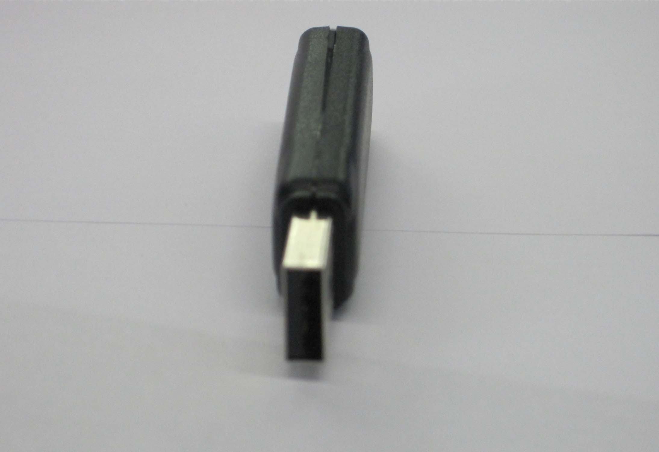
Electromagnetic Tracker - FCC ID YJUG4USB01 - Alken, Inc dba Polhemus
YJUG4USB01

Electromagnetic Tracker

Jan 03, 2011

Equipment Class

DSS - Part 15 Spread Spectrum Transmitter