YM9A-181Motorcycle alarm system
ZhongShan GL Electronics Co., LTD.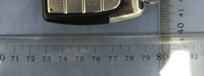
Click to zoom
Application Details
- Equipment Class
- DSC - Part 15 Security/Remote Control Transmitter
- Date of Grant
- Aug 18, 2010
- Application Purpose
- Original Equipment
- Date of Application
- Aug 18, 2010
- Equipment Note
- Motorcycle alarm system
- Frequency Range
- 433.92000000 - 433.92000000
- Country
- China
Documents & Files
Document Text
Text extracted from the exhibit documents filed with the FCC. Open a document above to read the original.
Users Manual
1 Motorcycle alarm system function instruction MODELGLM-3008-2, A-181 Function instruction arm Press the ARMING button once ,siren chirp once, parking light flash once, system enter into arming state in 3 seconds, LED begin flashing. Disarm Press DISARMING button once, siren chirp twice, parking light flash twice.( In the silent arming state the siren will not chirp) Silent arming Press ARMING button for 2 sec, parking light flash once, and the siren chirp once, and enter into silent arming state. Remote start Press STARTER button once, then press STARTER button once again in 1sec., motorcycle is started. Vehicle Finding Press SEARCH button once, parking lights flash 8 times, and the siren chirps 8 times at the same time Stop alarm In the alarm state, press DISARMING button disarm system, other button can stop alarm. Alarm In the arming state, the siren will chirp for 25seconds, parking light do not flash when the heavy shock trigger happen; if the shock trigger is light, the parking light flash 8 times and the siren chirps 8 times(in the silent arming state the siren will not chirp). If the system has trigger by “ACC ON”, in the arming state, the siren will chirps for 25 seconds and the parking lights will flash at the same time. Only press DISARMING button can disarm system, or will return to arming state after 25 seconds. Auto arm If auto arm function is activated, 1. if the ignition key is not turned to ON position in 30 after the system is deactivated, the system will rearm automatically . 2. ACC OFF, the siren will chirp for 3 times to indicate for arming the system; and 30 seconds latter the system will automatically enter arming state. Turn on or off the auto arm function: In disarming state , ACC ON then press and hold the DISARMING button for 5 seconds, the siren will chirps one to indicate the auto arm function is OFF, repeat above steps , the siren chirps twice indicate the auto arm function is ON . Overtake function In the driving state, press SEARCH button once , siren will chirp for 15 seconds, parking lights flash at the same time. press any button to stop it. Anti-hijack In the driving state, press ARMING button once, siren will long chirp, parking light flash at the same time. After 10seconds, engine shut down. Only press DISARMING button can disarm system State preservation If the power of the alarm system is cut off, no matter how long it is, after reconnect, alarm system will return to the state before power off. Code learning: Short circuit the JP1 on the main unit , the parking lights keep lighting indicate the system has enter into code learning state; press any button once on the remote in 3 seconds, parking light flash once indicate the remote learning is successful. Most of 4 remote can be learn to the system. if remote lost, or other reason need to learn new remote ,that the former remote will ineffective, should all the remote can use after learning again. 2 Shock sensitivity adjustment: Press and hold ARMING and DISARMING button at the same time for 2 seconds. After siren chirp 4 times, system enter into the 5 grade shock sensitivity adjustment state: then you can begin to adjust the shock sensitivity ; press and release the ARMING button ,the system will indicate you with the sound of “di--”(one “di” be heard indicate that you have selected the first grade shock sensitivity; and two “di” for the second grade, three “di” for the third grade, four “di” for the fourthly grade, five ‘di’ for the fifth grade ); 5 seconds after you selection , the system exit the shock sensitivity adjustment state automatically . (note: the first grade is the lowest grade, the fifth grade is the highest grade.) Select polarity for startup wire The blue wire provides a high current + or – output to start the engine of motorcycle (+ is the factory default setting). If the motorcycle has a negative startup circuit , the blue wire must be connect to black wire ; If the motorcycle has a positive startup circuit , the blue wire must be connect to red wire ; 3
External Photos
External Photos Enclosure of EUT Enclosure of EUT
ID Label/Location Info
15mm 7mm FCC IDYM9A-181 ModelA-181
Internal Photos
Internal Photos Internal of EUT PCB of EUT PCB of EUT
Operational Description
Operation Specification A-181---TX GLM-3008-2----RX Transmitter and Receiver ZhongShan GL Electronics Co., LTD. WanHua Building Jidongyi Wanhe Industrial, Xiaolan Town, Zhongshan, Guangdong ,China Tel: 0760-22133605 Fax: 0760-22133605 Note: The information contained in this document is proprietary and confidential any unauthorized reproduction, use or disclosure of this material, or any part thereof, is strictly prohibited. Receiver are all time ready to receive any signal including 433.92MHz, High frequency signal was filtered by 433.92MHz filter in receiver, then was demodulated by AM demodulator, low frequency digital signal that was demodulated, if it is strong and from TX(programming in advance), and the driver will power on the relay. (please refer above chart) Product photos: Remote control Receiver Relay ARMING button SEARCH button DISARMING STARTER button Function Diagram Function Description The product compose with two parts: A-181(Transmitter) and GLM-3008-2(Receiver) The product operate by wireless system, worked as bellowing description: Press the control key and you will switch on the power of signal, low frequency digit signal is mixed by mixer of AM signal of 433.92MHz, High frequency that was mixed and emitted by antenna in transmitter. (please refer above chart) Product technology parameters Value Parameter Min Typical Max unit Operating (Receiver) Voltage 11 12 14 V Quiescent current 3.7 4 4.5 Ma Current 3 3.2 4 A Temperature -20 30 60 Battery (Transmitter) Voltage 2.9 3.0 3.2 V capacity 210 mah Cut off @S+20 pulse current Size CR2032 Temperature range -10 50 Storage max. temp -10 50 Weight(approx) 3.0 g Frequency characteristics Frequency 433.92 MHz Bandwidth 600 KHz Modulation ASK
Test Report
Report No.: TR-1005-033-01 Page 1 of 24 TDK South China EMC Center SAE Technologies Development (Dongguan) Co., Ltd. Changan Branch FCC Test Report (TR-1005-033-01) Applicant : ZhongShan GL Electronics Co., LTD. Address : WanHua Building Jidongyi Wanhe Industrial, Xiaolan Town, Zhongshan, Guangdong ,China Manufacturer : ZhongShan GL Electronics Co., LTD. Address : WanHua Building Jidongyi Wanhe Industrial, Xiaolan Town, Zhongshan, Guangdong ,China Product Name : Motorcycle alarm system (Transmitter) Trademark : Model(s) : A-181, A-96, A-103, A-104, A-162, A-169, A-185, A-186 (All models have same schematics and other electronic parameter, only the enclosure is different for market purpose.) Standard(s) : FCC Part 15 Subpart C Test Result : Pass Date of Test : Jul. 15, 2010 to Jul. 19, 2010 Report issued Dated : Aug 10, 2010 The report shall not be reproduced except in full, without the written approval of the TDK EMC Center. The results in this report apply only to the sample(s) tested. The production units are required to conform to the initial sample as received when the units are placed in the market. Responsible Engineer : Approved by : Phenix Zhang Technical manager CHAN king-chui Date : 2010.08.10 Date : 2010.08.10 Report No.: TR-1005-033-01 Page 2 of 24 TDK South China EMC Center SAE Technologies Development (Dongguan) Co., Ltd. Changan Branch Table of Contents Description Page 1. Description of the Test Site ...................................................................................................................... 3 1.1 Test Site Location: ..................................................................................................................................... 3 1.2 Site Registration ....................................................................................................................................... 3 1.3 Test Scope................................................................................................................................................... 3 2. Description of the Tested Samples .......................................................................................................... 4 2.1 Customer Information .............................................................................................................................. 4 2.2 Identification of EUT ............................................................................................................................... 4 2.3 Spec of EUT .............................................................................................................................................. 4 2.4 Test Standards List.................................................................................................................................... 4 3. Test Specifications ....................................................................................................................................... 5 3.1 Standard(s) Used ....................................................................................................................................... 5 3.2 Deviations from the Test Specification .................................................................................................... 5 4. Test Result.................................................................................................................................................... 6 4.1 Antenna Requirement ............................................................................................................................... 6 4.2 Conducted Emission (mains).................................................................................................................... 7 4.3 Radiated Emission Test............................................................................................................................. 8 4.4 20dB Occupied Bandwidth..................................................................................................................... 15 4.5 Release Time Measurement.................................................................................................................... 17 5. FCC ID Label ............................................................................................................................................ 19 6. Test Setup ................................................................................................................................................... 20 6.1 Photographs of the Test Configuration ................................................................................................ 20 6.2 Photographs of the EUT ........................................................................................................................ 21 7. Equipment List.......................................................................................................................................... 23 8. Test Uncertainty ........................................................................................................................................ 24 9. Appendix .................................................................................................................................................... 24 9.1 Confirmation of Compliance within the Limits ................................................................................... 24 Report No.: TR-1005-033-01 Page 3 of 24 TDK South China EMC Center SAE Technologies Development (Dongguan) Co., Ltd. Changan Branch 1. Description of the Test Site 1.1 Test Site Location: Laboratory : TDK South China EMC Center SAE Technologies Development (Dongguan) Co., Ltd. Changan Branch Address : Zhenan Hi-tech Industrial Park, Dongguang City, Guangdong Province, China Phone no. : (86)-769-8564-4678 Fax no. : (86)-769-8564-4499 Email : [email protected] 1.2 Site Registration VCCI (September, 2008) : Reg. No. R-2205, C-2392 FCC site registration (July,…
Text truncated - open the document above for the full version.
Test Setup Photos
Radiated emission Below 1GHz: Above 1GHz:
Contact Information
Applicant
Xiaofeng Zhang(General Manager)
Test Firm
SAE Technologies Development(Dongguan)Co.,Ltd.Phenix Zang
Technical Specifications
| # | Rule Parts | Frequency Range | Power Output |
|---|---|---|---|
| 1 | 15.231 | 433.92 MHz - 433.92 MHz | - |