YMQ-8047000Laboratory Equipment with RFID
LRE Medical GmbH Esterline Corporation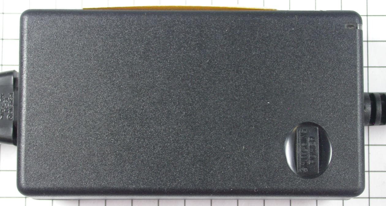
Click to zoom
Application Details
- Equipment Class
- DXX - Part 15 Low Power Communication Device Transmitter
- Date of Grant
- May 24, 2012
- Application Purpose
- Original Equipment
- Date of Application
- May 24, 2012
- Equipment Note
- Laboratory Equipment with RFID
- Frequency Range
- 13.56000000 - 13.56000000
- Country
- Germany
Documents & Files
Document Text
Text extracted from the exhibit documents filed with the FCC. Open a document above to read the original.
Users Manual
Astute140 TM Meter PN: 300005S Rev: B 2012 Astute Medical, Inc. 2012/03/17 [Company Logo] ASTUTE140 TM METER [PHOTO HERE] User Manual Astute140 TM Meter PN: 300005S Rev: B Astute Medical, Inc. 2012 2012/03/20 2 For performance evaluation only. Manufactured for Astute Medical, Inc. 3550 General Atomics Ct. Building 2 San Diego, CA 92121 USA MDSS GmbH Schiffgraben 41 30175 Hannover, Germany CONTACT INFORMATION: [email protected] Phone: +1 (858) 792-3544 Fax: +1 (858) 882-0449 [Add 800 number] [Add international number] Astute140 TM Meter PN: 300005S Rev: B Astute Medical, Inc. 2012 2012/03/20 3 Table of Contents INTRODUCTION ...................................................................................................................................................... 5 INTENDED USE ........................................................................................................................................................................ 5 PRINCIPLES OF OPERATION................................................................................................................................................... 5 METER KIT COMPONENTS ..................................................................................................................................................... 6 MATERIALS NEEDED BUT NOT PROVIDED ......................................................................................................................... 7 OPTIONAL ACCESSORIES ........................................................................................................................................................ 7 CONTACTING ASTUTE MEDICAL, INC. (TECHNICAL SUPPORT) ...................................................................................... 7 PRODUCT SPECIFICATIONS .................................................................................................................................................... 7 WARNINGS, HAZARDS, PRECAUTIONS, AND LIMITATIONS .............................................................................................. 8 Safety Symbols .......................................................................................................................................................................... 8 Safety Information .................................................................................................................................................................. 9 Limitations ............................................................................................................................................................................... 10 METER FEATURES ................................................................................................................................................................. 11 USER TYPES ........................................................................................................................................................................... 13 Operator .................................................................................................................................................................................... 13 Supervisor ................................................................................................................................................................................ 14 INSTALLATION ..................................................................................................................................................... 14 AC POWER SUPPLY ............................................................................................................................................................... 14 INSTALLATION AND REPLACEMENT OF BATTERIES ........................................................................................................ 15 INSTALLING OR CHANGING THE PAPER .............................................................................................................................. 16 POWERING ON THE METER ................................................................................................................................................. 17 SUPERVISOR INSTRUCTIONS: CONFIGURATION AND SETTINGS .................................................................................... 18 Adding the First Supervisor User ................................................................................................................................... 18 Set or change Time............................................................................................................................................................... 20 Set or Change Date .............................................................................................................................................................. 21 Set or Change the Language ............................................................................................................................................ 22 Updating System Software ............................................................................................................................................... 23 Update Meter Languages .................................................................................................................................................. 23 METER OPERATION ........................................................................................................................................... 23 STARTUP ................................................................................................................................................................................. 23 Power on the Meter .............................................................................................................................................................. 23 Log in ................…
Text truncated - open the document above for the full version.
Cover Letter(s)
Ersteller: D. Brandhorst Revision: 00 Erstelldatum: 02.01.2012 Datum: 00.00.0000 Seite 1 von 1 Long/Short-term Confidentiality Request PHOENIX TESTLAB GmbH Date: 23 May 2012 Product Certification Königswinkel 10 D 32825 Blomberg FCC ID: YMQ-8047000 To Whom it may concerns, Pursuant to sections 0.457(d) and 0.459 of CFR 47 and to avoid premature release of sensitive information prior to marketing or release of the product to the public, we hereby requests long-term confidential treatment of information accompanying this application as outlined below: Schematics Parts List Block Diagram Tune-Up Info Operational Description In addition we hereby request the following exhibits contained in this application to be temporarily (short-term confidentilality) withheld from the public disclosure for an initial period of 180 days until: not applicable External Photos Test Setup Photos Internal Photos Users Manual The above materials contain trade secrets and proprietary information not customarily released to the public. The public disclosure of these matters might be harmful to the applicant and provide unjustified benefits to its competitors. The applicant understands that pursuant to rule 0.457(d), disclosure of this application and all accompanying documentation will not be made before the date of the GRANT for this application. Thank you for your attention in this matter. Applicant’s Company address : mikes-testingpartners gmbh Ohmstr. 2-4, 94342 Strasskirchen, Germany Signature : Job Title and Dept. : Thomas Ring Certification Manager
External Photos
1 At t a c h m e n t A 1.1 Photo documentation of the EUT – external photos
ID Label/Location Info
Label Location
Internal Photos
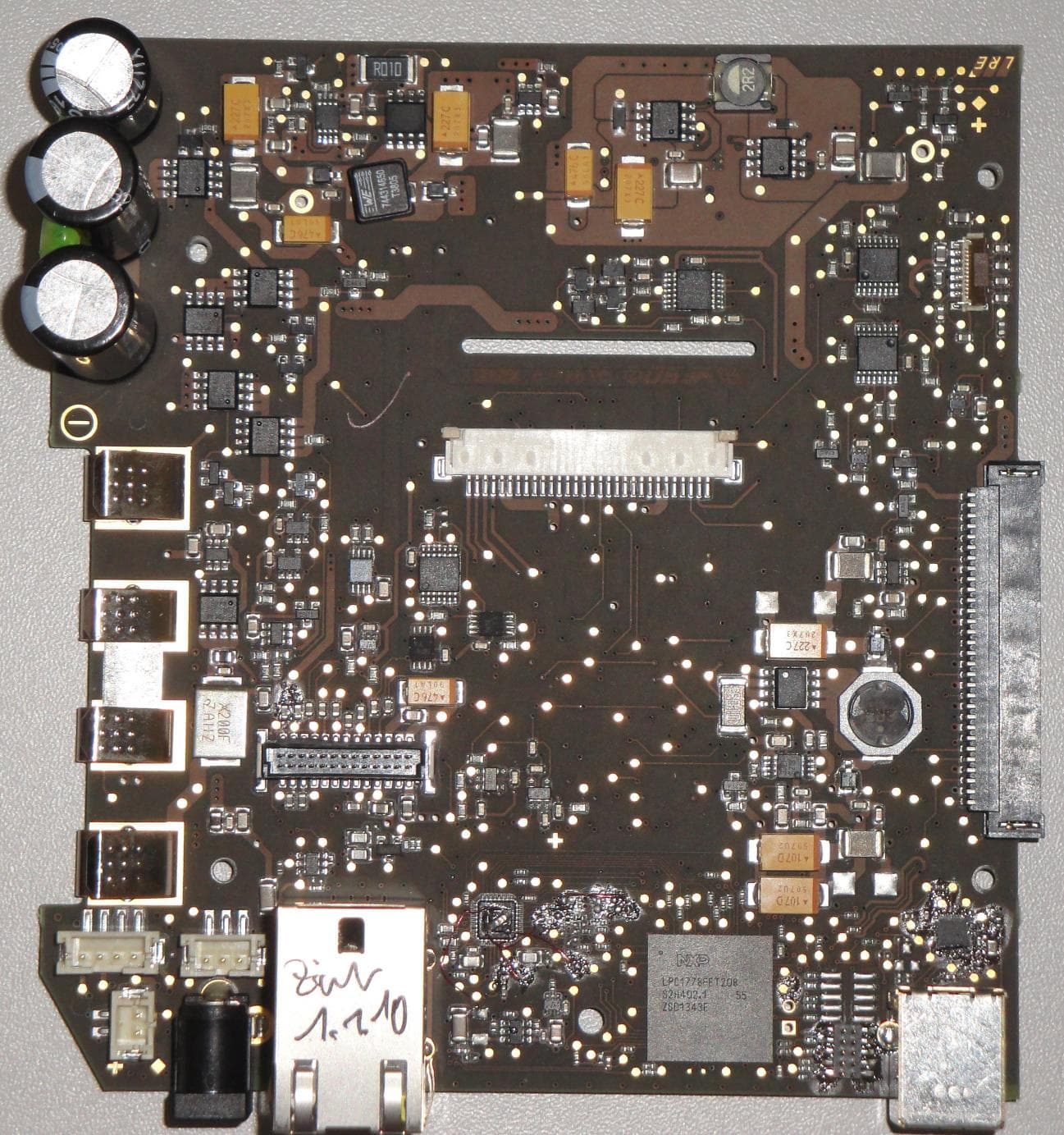
1.2 Photo documentation of the EUT – internal photos
Test Report
FCC ID: YMQ8047000 mikes-testingpartners gmbh File No. T35893-00-01KG, page 1 of 35 Ohmstrasse 2-4 94342 STRASSKIRCHEN GERMANY Tel.:+49(0)9424-94810 Fax:+49(0)9424-9481240 Rev. No. 1.1, 23.4.2009 EMI − T E S T R E P O R T - FCC Part 15.225 - Test Report No. : T35893-00-01KG 16. May 2012 ______________________________________________________________________________________________ Date of issue Type / Model Name : ASTUTE 140 Product Description : Laboratory Equipment with RFID Applicant : LRE Medical GmbH Address : Hofer Strasse 5 86720 Nördlingen, Germany Manufacturer : Astute Medical, Inc. Address : 3350 General Atomics Ct. San Diego, CA 92121, USA Licence holder : Astute Medical, Inc. Address : 3350 General Atomics Ct. San Diego, CA 92121, USA Test Result according to the standards listed in clause 1 test standards: POSITIVE The test report merely corresponds to the test sample. It is not permitted to copy extracts of these test results without the written permission of the test laboratory. FCC ID: YMQ8047000 mikes-testingpartners gmbh File No. T35893-00-01KG, page 2 of 35 Ohmstrasse 2-4 94342 STRASSKIRCHEN GERMANY Tel.:+49(0)9424-94810 Fax:+49(0)9424-9481240 Rev. No. 1.1, 23.4.2009 Contents 1 TEST STANDARDS 3 2 SUMMARY 4 3 EQUIPMENT UNDER TEST 5 3.1 Photo documentation of the EUT – See attachment A 5 3.2 Power supply system utilised 5 3.3 Short description of the equipment under test (EUT) 5 4 TEST ENVIRONMENT 6 4.1 Address of the test laboratory 6 4.2 Environmental conditions 6 4.3 Statement of the measurement uncertainty 6 4.1 Measurement Protocol for FCC, VCCI and AUSTEL 7 5 TEST CONDITIONS AND RESULTS 8 5.1 Conducted emissions 8 5.2 Field strength of the fundamental wave 12 5.3 Spurious emissions 14 5.4 Frequency tolerance 16 5.5 20 dB Bandwidth 18 5.6 Transmitter spectrum mask 21 5.7 Receiver radiated emissions 24 6 USED TEST EQUIPMENT AND ACCESSORIES 25 7 Attachment A 26 7.1 Photo documentation of the EUT – external photos 26 7.2 Photo documentation of the EUT – internal photos 29 FCC ID: YMQ8047000 mikes-testingpartners gmbh File No. T35893-00-01KG, page 3 of 35 Ohmstrasse 2-4 94342 STRASSKIRCHEN GERMANY Tel.:+49(0)9424-94810 Fax:+49(0)9424-9481240 Rev. No. 1.1, 23.4.2009 1 TEST STANDARDS The tests were performed according to following standards: FCC Rules and Regulations Part 15, Subpart A - General (September, 2011) Part 15, Subpart A, Section 15.31 Measurement standards Part 15, Subpart A, Section 15.33 Frequency range of radiated measurements Part 15, Subpart A, Section 15.35 Measurement detector functions and bandwidths Part 15, Subpart A, Section 15.38 Incorporation by reference FCC Rules and Regulations Part 15, Subpart C - Intentional Radiators (September, 2011) Part 15, Subpart C, Section 15.203 Antenna requirement Part 15, Subpart C, Section 15.204 External radio frequency power amplifiers and antenna modifications Part 15, Subpart C, Section 15.205 Restricted bands of operation Part 15, Subpart C, Section 15.207 Conducted limits Part 15, Subpart C, Section 15.209 Radiated emission limits, general requirements Part 15, Subpart C, Section 15.215 Additional provisions to the general radiated emission limitations Part 15, Subpart C, Section 15.225 Operation within the band 13.110 - 14.010 MHz FCC Rules and Regulations Part 1, Subpart I - Procedures Implementing the National Environmental Policy Act of 1969 Part 1, Subpart I, Section 1.1310 Radiofrequency radiation exposure limits Part 1, Subpart 2, Section 2.1093 Radiofrequency radiation exposure evaluation: portable device OET Bulletin 65, 65A, 65B, 65C Edition 97-01, August 1997 – Evaluating Compliance with FCC Guidelines for Human Exposure to Radio Frequency Electromagnetic Fields. ANSI C63.4: 2009 Methods of Measurement of Radio-Noise Emissions from Low- Voltage Electrical and Electronic Equipment in the Range of 9 kHz to 40 GHz. ANSI C95.1:1992 IEEE Standard for Safety Levels with respect to Human Exposure to Radio Frequency Electromagnetic Fields, 3 kHz to 300 GHz CISPR 16-4-2: 2003 Uncertainty in EMC measurement FCC ID: YMQ8047000 mikes-testingpartners gmbh File No. T35893-00-01KG, page 5 of 35 Ohmstrasse 2-4 94342 STRASSKIRCHEN GERMANY Tel.:+49(0)9424-94810 Fax:+49(0)9424-9481240 Rev. No. 1.1, 23.4.2009 3 EQUIPMENT UNDER TEST 3.1 Photo documentation of the EUT – See attachment A 3.2 Power supply system utilised Power supply voltage : Battery 6.0 VDC AC 115 V / 60 Hz / 1 3.3 Short description of the equipment under test (EUT) The ASTUTE reader is a portable fluorescence instrument for a laboratory setting. Each test cartridge includes an RFID tag that identfies relevant parameter for evaluating the test results. Number of tested samples: 1 Serial number: 00001057 EUT operation mode: The equipment under test was operated during the measurement under the following conditions: - TX pulsed modulated at 13,56 MHz EUT configuration: (The CDF filled by the applicant can be viewed at the test laboratory.) The following peripheral devices and interface cables were connected during the measurements: - RFID-TAG Model : Customer specific - Model : - Model : FCC ID: YMQ8047000 mikes-testingpartners gmbh File No. T35893-00-01KG, page 6 of 35 Ohmstrasse 2-4 94342 STRASSKIRCHEN GERMANY Tel.:+49(0)9424-94810 Fax:+49(0)9424-9481240 Rev. No. 1.1, 23.4.2009 4 TEST ENVIRONMENT 4.1 Address of the test laboratory mikes-testingpartners gmbh Ohmstrasse 2-4 94342 STRASSKIRCHEN GERMANY 4.2 Environmental conditions During the measurement the environmental conditions were within the listed ranges: Temperature: 15-35 ° C Humidity: 30-60 % Atmospheric pressure: 86-106 kPa 4.3 Statement of the measurement uncertainty The data and results referenced in this document are true and accurate. The reader may notice that tolerances within the calibration of the equipment and facilities may cause additional uncertainty. The measurement uncertainty is calculated for all measurements listed in this test report acc. to CISPR …
Text truncated - open the document above for the full version.
Test Setup Photos
FCC ID: YMQ8047000 mikes-testingpartners gmbh File No. T35893-00-01KG, page 8 of 35 Ohmstrasse 2-4 94342 STRASSKIRCHEN GERMANY Tel.:+49(0)9424-94810 Fax:+49(0)9424-9481240 Rev. No. 1.1, 23.4.2009 5 TEST CONDITIONS AND RESULTS 5.1 Conducted emissions For test instruments and accessories used see section 6 Part A 4. 5.1.1 Description of the test location Test location: Shielded Room S2 5.1.2 Photo documentation of the test set-up 5.1.3 Applicable standard According to FCC Part 15, Section 15.207(a): Except as shown in paragraphs (b) and (c) of this Section, for an intentional radiator that is designed to be connected to the public utility (AC) power line, the radio frequency voltage that is conducted back onto the AC power line on any frequency or frequencies within the band 150 kHz to 30 MHz shall not exceed the given limits. 5.1.4 Description of Measurement The measurements are performed following the procedures set out in ANSI C63.4 described under item 4.4.3. If the minimum limit margin appears to be less than 20 dB with a peak mode measurement, the emissions are remeasured using a tuned receiver with quasi-peak and average detection and recorded on the data sheets. FCC ID: YMQ8047000 mikes-testingpartners gmbh File No. T35893-00-01KG, page 12 of 35 Ohmstrasse 2-4 94342 STRASSKIRCHEN GERMANY Tel.:+49(0)9424-94810 Fax:+49(0)9424-9481240 Rev. No. 1.1, 23.4.2009 5.2 Field strength of the fundamental wave For test instruments and accessories used see section 6 Part CPR 1. 5.2.1 Description of the test location Test location: OATS1 Test distance: 3 metres 5.2.2 Photo documentation of the test set-up FCC ID: YMQ8047000 mikes-testingpartners gmbh File No. T35893-00-01KG, page 14 of 35 Ohmstrasse 2-4 94342 STRASSKIRCHEN GERMANY Tel.:+49(0)9424-94810 Fax:+49(0)9424-9481240 Rev. No. 1.1, 23.4.2009 5.3 Spurious emissions For test instruments and accessories used see section 6 Part SER 1, SER 2. 5.3.1 Description of the test location Test location: OATS1 Test distance: 3 metres 5.3.2 Photo documentation of the test set-up FCC ID: YMQ8047000 mikes-testingpartners gmbh File No. T35893-00-01KG, page 16 of 35 Ohmstrasse 2-4 94342 STRASSKIRCHEN GERMANY Tel.:+49(0)9424-94810 Fax:+49(0)9424-9481240 Rev. No. 1.1, 23.4.2009 5.4 Frequency tolerance For test instruments and accessories used see section 6 Part FE. 5.4.1 Description of the test location Test location: AREA4 (Climatic Chamber) 5.4.2 Photo documentation of the test set-up 5.4.3 Applicable standard According to FCC Part 15, Section 15.225(e): The frequency tolerance of t he carrier signal shall be maintained within ±0.01 % of the operating frequency over a temperature range of -20 °C to +50 °C at normal supply voltage and for a variation in the primary supply voltage from 85 % to 115 % of the rated supply voltage at a temperature of 20 °C. For battery operated equipment, the equipment shall be performed using a new battery. 5.4.4 Description of Measurement The frequency tolerance has been measured radiated using a spectrum analyser. The center frequency of the spectrum analyser has been set to the fundamental frequency. This is an alternative test method because the EuT can not be operated in un-modulated mode. The limit line was set to 10 dB below the carrier. The frequencies of the upper (f U ) and lower (f L ) points, where the displayed power envelope of the modulation including frequency drift is equal to the appropriate level, have been recorded. The centre frequency is calculated as f C = (f U + f L )/2. The measurement has been performed at normal and extreme test conditions from -20 °C to +50 °C in steps of 10 degrees (According to FCC Part 2.1055). FCC ID: YMQ8047000 mikes-testingpartners gmbh File No. T35893-00-01KG, page 18 of 35 Ohmstrasse 2-4 94342 STRASSKIRCHEN GERMANY Tel.:+49(0)9424-94810 Fax:+49(0)9424-9481240 Rev. No. 1.1, 23.4.2009 5.5 20 dB Bandwidth For test instruments and accessories used see section 6 Part MB. 5.5.1 Description of the test location Test location: AREA4 5.5.2 Photo documentation of the test set-up 5.5.3 Applicable standard According to FCC Part 15C, Section 15.215(c): Intentional radiators operating under the alternative provisions to the general emission limits, as contained in section 15.217 to 15.257, must be designed to ensure that the 20 dB bandwidth of the emission is contained within the frequency band designated in the rule section under which the equipment is operated. The requirement to contain the designated bandwidth of the emission within the specified frequency band includes the effects from frequency sweeping, frequency hopping and other modulation techniques that may be employed. FCC ID: YMQ8047000 mikes-testingpartners gmbh File No. T35893-00-01KG, page 21 of 35 Ohmstrasse 2-4 94342 STRASSKIRCHEN GERMANY Tel.:+49(0)9424-94810 Fax:+49(0)9424-9481240 Rev. No. 1.1, 23.4.2009 5.6 Transmitter spectrum mask For test instruments and accessories used see section 6 Part MB. 5.6.1 Description of the test location Test location: AREA4 5.6.2 Photo documentation of the test set-up
Contact Information
Applicant
Johann Meyr(Director Quality Assurance)
Test Firm
CSA Group Bayern GmbHThomas Weise
Technical Specifications
| # | Rule Parts | Frequency Range | Power Output | Tolerance |
|---|---|---|---|---|
| 1 | 15C | 13.56 MHz - 13.56 MHz | - | 0.0100000000 % |
Other Applications from LRE Medical GmbH Esterline Corporation
YMQ-8048000
Nov 05, 2014RFID Reader
Equipment Class
DXX - Part 15 Low Power Communication Device Transmitter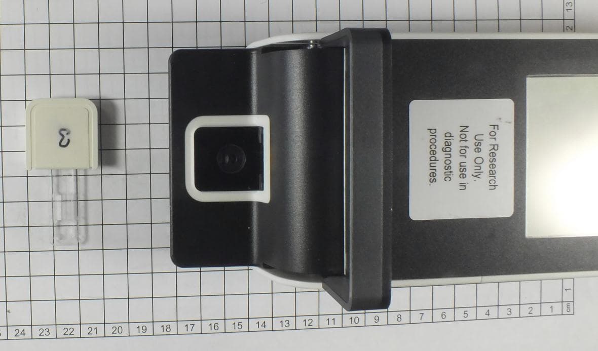
YMQ-8066000
Jan 24, 2013Laboratory Equipment with RFID
Equipment Class
DXX - Part 15 Low Power Communication Device Transmitter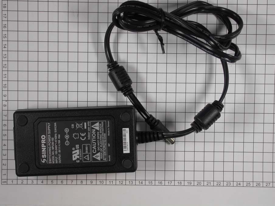
YMQ-8051000
Aug 16, 2010Apex Reader
Equipment Class
DXX - Part 15 Low Power Communication Device Transmitter