YMX-EC7510WLCWireless-charging
XIAMEN COMFORT SCIENCE & TECHNOLOGY GROUP CO., LTD
Click to zoom
Application Details
- Equipment Class
- DCD - Part 15 Low Power Transmitter Below 1705 kHz
- Date of Grant
- Sep 20, 2020
- Application Purpose
- Original Equipment
- Date of Application
- Sep 20, 2020
- Equipment Note
- Wireless-charging
- Frequency Range
- 0.11000000 - 0.20500000
- Country
- China
Documents & Files
Document Text
Text extracted from the exhibit documents filed with the FCC. Open a document above to read the original.
Users Manual
/ 2 USER MANUAL Product:wireless-charging Model No.:EC-7510-WLC This is a wireless charger that will charge any device that supports the Qi standard, Please read the user manual before using and keep itfor future reference.wireless charging transmitter is a wireless charging solution based on electromagnetic induction technology provided by CPS . It is compatible with QI-BPP/Samsung Fast charging standard, with charging area up to 10mm*10mm and output power of 5W/ 7.5w /10W, supporting Apple fast charging. Specifications: Input: 12~24V±5% Wireless Charging Output: 10W (Max.) Coil module dimensions:D:500mm,H:3.8mm Efficiency:70% Min Charge area:10mm*10mm Use procedure: 1. power by DC 12V/24V 2.We can put the mobile phone or iPad right above the device 3.The device is charging 4.When the phone is fully charged, the wireless charger remains in standby mode / 2 FCC Label Compliance Statement: This device complies with Part 15 of the FCC Rules. Operation is subject to the following two conditions: (1) This device may not cause harmful interference (2) This device must accept any interference received, including interference that may cause undesired operation.Any changes or modifications not expressly approved by the grantee of this device could void the user's authority to operate the equipment. Declaration the Restriction of this Limited Module Approval: According to FCC Part 15 Subpart C Section 15.212, the radio elements of the modular transmitter must have their own shielding. However, due to there is no shielding for this Module, this module is granted as a Limited Modular Approval. When this Module is installed into the end product, a Class II Permissive Change or a New FCC ID submission is required to ensure the full compliance of FCC relevant requirements. Under such configuration, the FCC radiation exposure limits set forth for an opulation/uncontrolled environment can be satisfied. Only FCC approved antenna can be used for the module integrated into host. The module only use for XIAMEN COMFORT SCIENCE & TECHNOLOGY GROUP CO., LTD , not sale to the third parties.
Cover Letter(s)
XIAMEN COMFORT SCIENCE & TECHNOLOGY GROUP CO., LTD Agent Authorization Letter 2020-09-16 MET Laboratories, Inc. 914 West Patapsco Avenue Baltimore, MD 21230 RE: LETTER OF AGENT AUTHORIZATION To Whom It May Concern: We, the undersigned, hereby authorize Shenzhen Huaxia Testing Technology Co., Ltd. to act on our behalf in all matters relating to application for equipment authorization, including the signing of all documents relating to these matters. We also hereby certify that no party to the application authorized hereunder is subject to the denial of benefits, including FCC benefits, pursuant to Section 5301 of the Anti-Drug Abuse Act of 1988, 21 U.S.C.853(a). This agreement expires one year from the current date. Sincerely, Name: Pengfei Cui Position: Safety Engineer Company Name: XIAMEN COMFORT SCIENCE & TECHNOLOGY GROUP CO., LTD Address: (5/F) NO.168, QIANPU ROAD, SIMING DISTRICT, XIAMEN, China Tel / Fax +86-592-7266925/ +86-592-5532788 E-Mail: [email protected]
Cover Letter(s)
XIAMEN COMFORT SCIENCE & TECHNOLOGY GROUP CO., LTD Long Term Confidentiality Request Letter 2020-09-16 MET Laboratories, Inc. 914 West Patapsco Avenue Baltimore, MD 21230 RE: CONFIDENTIALITY REQUEST FOR (FCC ID: YMX-EC7510WLC) To Whom It May Concern: This letter serves as an official request for confidentiality under sections 0.457 and 0.459 of CFR 47. We have requested that the - e.g. Block diagram - e.g. SCH - e.g. Operational Description required to be submitted with this application be permanently withheld from public review. The above documents are company proprietary information that could never get into the possession of your competition. Please contact me if there is any information you may need. Sincerely, Name: Pengfei Cui Position: Safety Engineer Company Name: XIAMEN COMFORT SCIENCE & TECHNOLOGY GROUP CO., LTD Address: (5/F) NO.168, QIANPU ROAD, SIMING DISTRICT, XIAMEN, China Tel / Fax +86-592-7266925/ +86-592-5532788 E-Mail: [email protected]
Cover Letter(s)
XIAMEN COMFORT SCIENCE & TECHNOLOGY GROUP CO., LTD Request for Modular/Limited Modular Approval Date: September 17, 2020 Subject: Manufacturer’s Declaration for ☐ -Modular Approval ☐ - SplitModular Approval ☒- Limited Modular Approval ☐- Limited Split Modular Approval Confidentiality Request for: ______ YMX-EC7510WLC ______ 8 Basic Requirements – FCC Part 15.212(a)(1) For Items Marked “NO(*)”, the Limited Module Description Must be Filled Out on the Following Pages Modular Approval Requirement Requirement Met 1. The modular transmitter must have its own RF shielding. This is intended to ensure that the module does not have to rely upon the shielding provided by the device into which it is installed in order for all modular transmitter emissions to comply with FCC limits. It is also intended to prevent coupling between the RF circuitry of the module and any wires or circuits in the device into which the module is installed. Such coupling may result in non-compliant operation. The physical crystal and tuning capacitors may be located external to the shielded radio elements. 15.212(a)(1)(i) ☐- YES ☒ - NO(*) Details: <example – The module contains a metal shield which covers all RF components and circuitry. The shield is located on the top of the board next to antenna connector> 2. The modular transmitter must have buffered modulation/data inputs (if such inputs are provided) to ensure that the module will comply with FCC requirements under conditions of excessive data rates or over-modulation. 15.212(a)(1)(ii) ☒ - YES ☐ - NO(*) Details: <example – Data to the modulation circuit is buffered as described in the operational description provided with the application> 3. The modular transmitter must have its own power supply regulation on the module. This is intended to ensure that the module will comply with FCC requirements regardless of the design of the power supplying circuitry in the device into which the module is installed. 15.212(a)(1)(iii) ☒ - YES ☐ - NO(*) Details: <example – The module contains its own power supply regulation. Please refer to schematic filed with this application> 4. The modular transmitter must comply with the antenna and transmission system requirements of §§ 15.203, 15.204(b), 15.204(c), 15.212(a), and 2.929(b). The antenna must either be permanently attached or employ a ‘‘unique’’ antenna coupler (at all connections between the module and the antenna, including the cable). The ‘‘professional installation’’ provision of § 15.203 is not applicable to modules but can apply to limited modular approvals under paragraph 15.212(b). 15.212(a)(1)(iv) ☒ - YES ☐ - NO(*) Details: <example – The module connects to its antenna using an UFL connector which is considered a non-standard connector. A list of antennas tested and approved with this device may be found in users manual provided with the application> 5. The modular transmitter must be tested in a stand-alone configuration, i.e., the module must not be inside another device during testing. This is intended to demonstrate that the module is capable of complying with Part 15 emission limits regardless of the device into which it is eventually installed. Unless the transmitter module will be battery powered, it must comply with the AC line conducted requirements found in Section 15.207. AC or DC power lines and data input/output lines connected to the module must not contain ferrites, unless they will be marketed with the module (see Section 15.27(a)). The length of these lines shall be length typical of actual use or, if that length is unknown, at least 10 centimeters to insure that there is no coupling between the case of the module and supporting equipment. Any accessories, peripherals, or support equipment connected to the module during testing shall be unmodified or commercially available (see Section 15.31(i)). 15.212(a)(1)(v) ☒ - YES ☐ - NO(*) Details: <example – The module was tested stand-alone as shown in test setup photographs filed with this application> XIAMEN COMFORT SCIENCE & TECHNOLOGY GROUP CO., LTD Modular Approval Requirement Requirement Met 6. The modular transmitter must be labeled with its own FCC ID number, or use an electron display (see KDB Publication 784748). If using a permanently affixed label with its own FCC ID number, if the FCC ID is not visible when the module is installed inside another device, then the outside of the device into which the module is installed must also display a label referring to the enclosed module. This exterior label can use wording such as the following: “Contains Transmitter Module FCC ID: XYZMODEL1” or “Contains FCC ID: XYZMODEL1.” Any similar wording that expresses the same meaning may be used. The Grantee may either provide such a label, an example of which must be included in the application for equipment authorization, or, must provide adequate instructions along with the module which explain this requirement. In the latter case, a copy of these instructions must be included in the application for equipment authorization. If the modular transmitter uses an electronic display of the FCC identification number, the information must be readily accessible and visible on the modular transmitter or on the device in which it is installed. If the module is installed inside another device, then the outside of the device into which the module is installed must display a label referring to the enclosed module. This exterior label can use wording such as the following: “Contains FCC certified transmitter module(s).” Any similar wording that expresses the same meaning may be used. The user manual must include instructions on how to access the electronic display. A copy of these instructions must be included in the application for equipment authorization. 15.212(a)(1)(vi) ☒ - YES ☐ - NO(*) Details: <example – There is a label on the module as shown in the labeling exhibit filed with this application. Host specific labeling instructions are shown in the installation manual .fi…
Text truncated - open the document above for the full version.
External Photos
Test Model No.: EC7510WLC
ID Label/Location Info
Model No.: EC-7510-WLC FCC ID: YMX-EC7510WLC Thursday, November 22, 2018 B E801C-TX V0.4 2 2 Control of Sheet Date: Rev Document Number Size Title CLOSE TO IC close to EC8012 pin this trace should avoid Vias A B C D 5 4 3 2 1 D C B A 1 2 3 4 5 1 2 C14 DNP 0.1uF 1 2 C4 22uF 1 2 C17 10uF 1 2 C36 0.01uF 1 2 R45 1K 1 TP32 1 LDO3P3 2 PGND 3 SW 4 VIN 5 BST 6 ENB 7 AVDD 8 DVDD 11 LED1 12 LED2 13 MISO 14 MOSI 15 SWCLK 25 COMM 26 NC1 28 SNSP 29 SNSN 27 SNSOUT 30 AIN0 31 NTC 32 AIN1 33 RFOD 34 DP 35 DN 37 AIN2 38 FOD 39 NC2 40 BST2 41 DRVH2 42 SW2 43 DRVL2 44 DRVL1 45 SW1 46 DRVH1 47 BST1 48 PVDD 9 NC4 10 NC3 36 AGND 16 DGND 24 GP0 23 GP1 22 GP2 21 GP3 20 GP4 19 GP5 18 GP6 17 GP7 49 EPGND U1 EC8012 1 2 C33 0.1uF 1 4 2 6 3 5 9 8 7 U2 RU30J30M 1 2 C10 0.1uF 1 TP1 1 2 R10 22 1 2 R49 0 1 TP19 1 2 R4 22 1 TP5 1 2 C9 DNP 0.1uF 1 2 R32 33K 1 2 C25 0.1uF 2 1 4 3 D3 CMH02-32RG10C 2 1 D6 L1N4148WT1G 2 GND 3 OUT 4 VCC 1 EN U9 1 2 R54 0 1 2 C5 0.047uF 1 2 R19 5.1K 1 2 C26 0.01uF 1 2 C8 0.4uF 1 2 C13 2700pF 1 2 C19 4.7uF 1 2 L1 4.7uH 1 TP33 1 4 2 6 3 5 9 8 7 U4 RU30J30M 1 2 R5 3.3 1 2 C2 22uF 1 TP12 1 2 C37 DNP 22uF 1 TP28 1 TP34 1 2 C12 DNP 0.1uF 1 2 C27 0.015uF 1 2 C16 4.7uF 1 2 C22 0.1uF 1 2 R22 1K 1 2 C1 1000pF 1 2 C20 6800pF 1 2 C23 2700pF 1 2 C7 10uF 1 TP29 1 2 C39 DNP 22uF 1 TP8 1 2 R53 0 1 2 C28 DNP 0.01uF 1 2 R50 0 1 2 R2 22 1 TP10 1 2 R35 5.1K 1 2 C34 0.1uF 1 2 R17 3.3 1 2 R52 510 1 2 R26 33K 1 2 R3 10K 1 2 D2 SMF12CA 1 TP22 1 TP15 1 2 C29 15pF 1 2 C21 22uF 1 2 R7 3K 1 2 R21 1K 1 TP30 1 2 C3 0.1uF 1 2 R6 22 1 1 2 2 J1 COIL 1 2 R25 33K 1 2 C11 DNP 0.1uF 1 2 C38 22uF 1 2 C24 2200pF 1 2 C35 0.1uF 2 1 R27 10K 1 TP31 1 TP9 1 2 R30 3.3K 1 TP11 1 2 R31 1.5K 1 2 C18 0.047uF 1 TP17 1 2 R11 0.02 1 2 R1 0 1 2 C6 0.047uF 1 2 R51 510 1 2 R16 DNP 5.1K 1 2 R46 8.2K 1 2 R12 0 1 2 C30 0.1uF 1 2 C15 2200pF 1 2 C32 0.1uF 1 TP27 1 TP23 1 2 R55 39K 1 2 R56 39K 1 2 R61 0 1 2 C41 0.1uF 1 2 R57 0/DNP 1 2 C42 0.01uF/DNP 1 2 C44 0.01uF/DNP 1 2 R58 33K/DNP 1 2 R60 1.5K/DNP 1 2 C43 0.01uF/DNP 1 2 R59 3.3K/DNP +9V +9V +9V 1_8V 1_8V +9V 3_3V 5V 5V 3_3V +9V DRVL1 M_HG_A1 TEST BUCK_OUT DRVH1 FODA SWCLK ENV_RC BUCK_SW BK_BST DRVH2 AGND_EXTERNAL COMMA SNSN SNSP COUP_CAP SNUB_RC1 SW2 P_GND GP1 MOSI SNSOUT COMMB M_HG_A2 DR_BST2 DR_BST2 5V M_LG_A2 DRVL2 SNUB_RC2 BST MISO MISO GP0 ENB TXD FODB COIL_A NTC_A SW1 BST1_RC BST1_RC 17V D+ D+ D- D- SWCLK AGND_EXTERNAL AGND_EXTERNAL AGND_EXTERNAL AGND_EXTERNAL SNSN SNSP P_GND P_GND P_GND GP1 MOSI MISO MISO GP0 NTC_A D+ D- 5V SNSB AGND_EXTERNAL COUP_CAP AGND_EXTERNAL COUP_CAP-2 ENV_RC-2 ENV_DC PAC102PAC101 COC1 PAC202 PAC201 COC2 PAC302 PAC301 COC3 PAC402 PAC401 COC4 PAC502PAC501 COC5 PAC602PAC601 COC6 PAC702PAC701 COC7 PAC802 PAC801 COC8 PAC902 PAC901 COC9 PAC1002 PAC1001 COC10 PAC1102 PAC1101 COC11 PAC1202 PAC1201 COC12 PAC1302PAC1301 COC13 PAC1402 PAC1401 COC14 PAC1502 PAC1501 COC15 PAC1602 PAC1601 COC16 PAC1702PAC1701 COC17 PAC1802PAC1801 COC18 PAC1902PAC1901 COC19 PAC2002 PAC2001 COC20 PAC2102 PAC2101 COC21 PAC2202 PAC2201 COC22 PAC2302PAC2301 COC23 PAC2402PAC2401 COC24 PAC2502PAC2501 COC25 PAC2602PAC2601 COC26 PAC2702PAC2701 COC27 PAC2802PAC2801 COC28 PAC2902 PAC2901 COC29 PAC3002PAC3001 COC30 PAC3102 PAC3101 COC31 PAC3202PAC3201 COC32 PAC3302PAC3301 COC33 PAC3402PAC3401 COC34 PAC3502 PAC3501 COC35 PAC3602 PAC3601 COC36 PAC3702 PAC3701 COC37 PAC3802PAC3801 COC38 PAC3902 PAC3901 COC39 PAC4002 PAC4001 COC40 PAC4102PAC4101 COC41 PAC4202PAC4201 COC42 PAC4302PAC4301 COC43 PAC4402PAC4401 COC44 PAC4502 PAC4501 COC45 PAC4602 PAC4601 COC46 PAC4702PAC4701 COC47 PAC4802PAC4801 COC48 PAC4902PAC4901 COC49 PAC5002PAC5001 COC50 PAC5102PAC5101 COC51 PAC5202PAC5201 COC52 PAC5302PAC5301 COC53 PAD102 PAD101 COD1 PAD202PAD201 COD2 PAD304PAD303 PAD302PAD301 COD3 PAD602 PAD601 COD6 PA J100 CO J1 PAJ102PAJ101 COJ1 PAJ202 PAJ201 COJ2 PAL102 PAL101 COL1 PAL202 PAL201 COL2 PAL302 PAL301 COL3 PAL404 PAL403PAL402 PAL401 COL4 PAL501PAL502 COL5 PAR102PAR101 COR1 PAR202 PAR201 COR2 PAR302PAR301 COR3 PAR402 PAR401 COR4 PAR502 PAR501 COR5 PAR602 PAR601 COR6 PAR702PAR701 COR7 PAR802PAR801 COR8 PAR902PAR901 COR9 PAR1002 PAR1001 COR10 PAR1102 PAR1101 COR11 PAR1202PAR1201 COR12 PAR1302PAR1301 COR13 PAR1402PAR1401 COR14 PAR1502 PAR1501 COR15 PAR1602 PAR1601 COR16 PAR1702 PAR1701 COR17 PAR1902PAR1901 COR19 PAR2102PAR2101 COR21 PAR2202PAR2201 COR22 PAR2502 PAR2501 COR25 PAR2602 PAR2601 COR26 PAR2702PAR2701 COR27 PAR3002PAR3001 COR30 PAR3102PAR3101 COR31 PAR3202PAR3201 COR32 PAR3502PAR3501 COR35 PAR4502PAR4501 COR45 PAR4602PAR4601 COR46 PAR4902 PAR4901 COR49 PAR5002 PAR5001 COR50 PAR5102 PAR5101 COR51 PAR5202 PAR5201 COR52 PAR5302 PAR5301 COR53 PAR5402 PAR5401 COR54 PAR5502PAR5501 COR55 PAR5602PAR5601 COR56 PAR5702PAR5701 COR57 PAR5802PAR5801 COR58 PAR5902PAR5901 COR59 PAR6002PAR6001 COR60 PAR6102PAR6101 COR61 PATP101 COTP1 PATP501 COTP5 PATP801 COTP8 PATP901 COTP9 PATP1101 COTP11 PATP1501 COTP15 PATP1701 COTP17 PATP1901 COTP19 PATP2201 COTP22 PATP2301 COTP23 PATP2701 COTP27 PATP2901 COTP29 PATP3001 COTP30 PATP3101 COTP31 PATP3201 COTP32 PATP3301 COTP33 PATP3401 COTP34 PAU1049 PAU1048PAU1047PAU1046PAU1045PAU1044PAU1043PAU1042PAU1041PAU1040PAU1039PAU1038PAU1037 PAU1036 PAU1035 PAU1034 PAU1033 PAU1032 PAU1031 PAU1030 PAU1029 PAU1028 PAU1027 PAU1026 PAU1025 PAU1024PAU1023PAU1022PAU1021PAU1020PAU1019PAU1018PAU1017PAU1016PAU1015PAU1014PAU1013 PAU1012 PAU1011 PAU1010 PAU109 PAU108 PAU107 PAU106 PAU105 PAU104 PAU103 PAU102 PAU101 COU1 PAU2011 PAU2010 PAU209 PAU208PAU207PAU206PAU205 PAU204PAU203PAU202PAU201 COU2 PAU309 PAU308PAU307PAU306PAU305 PAU304PAU303PAU302PAU301 COU3 PAU4011 PAU4010 PAU409 PAU408PAU407PAU406PAU405 PAU404PAU403PAU402PAU401 COU4 PAU904PAU903 PAU902PAU901 COU9 PAC801 PA J100 PAL404 PAC802 PA J100 PAL403 PAC201 PAC301 PAC401 PAC1001 PAC2101 PAC2201 PAC3701 PAC3801 PAC3901 PAC4801 PAC4902 PAC5002 PAC5102 PAC5301 PAD202 PAJ201 PAL202 PAR1401 PATP3301 PAU104 PAU202PAU203PAU204 PAU2010 PAU2011 PAU402PAU403PAU404 PAU4010 PAU4011 PAC1901 PAC3401 PAR1902 PATP1101 PAU108 PAC1601 PAC3501 PAC3601 PAU101 PAU901 PAU904 PAC1701 PAC3…
Text truncated - open the document above for the full version.
RF Exposure Info
Shenzhen Huaxia Testing Technology Co., Ltd 1F., Block A of Tongsheng Technology Building, Huahui Road, Dalang Street, Longhua District, Shenzhen, China Telephone: +86-755-26648640 Fax: +86-755-26648637 Website: www.cqa-cert.com Report Template Version: V04 Report Template Revision Date: 2018-07-06 RF Exposure Evaluation Report The test report is effective only with both signature and specialized stamp, The result(s) shown in this report refer only to the sample(s) tested. Without written approval of CQA, this report can’t be reproduced except in full. Report No.: CQASZ20200800842E-02 Applicant: XIAMEN COMFORT SCIENCE & TECHNOLOGY GROUP CO., LTD. Address of Applicant: (5/F) NO.168, QIANPU ROAD, SIMING DISTRICT, XIAMEN, CHINA Equipment Under Test (EUT): Product: wireless-charging Model No.: EC-7510-WLC Brand Name: N/A FCC ID: YMX-EC7510WLC Standards: 47 CFR Part 1.1307 47 CFR Part 1.1310 KDB 680106 D01 RF Exposure Wireless Charging Base App v03 Date of Receipt: 2020-08-12 Date of Test: 2020-08-12 to 2020-09-01 Date of Issue: 2020-09-01 Test Result : PASS* *In the configuration tested, the EUT complied with the standards specified above Tested By: (Martin Lee) Reviewed By: (Sheek Luo) Approved By: (Jack Ai) Shenzhen Huaxia Testing Technology Co., Ltd Report No.: CQASZ20200800842E-02 Page:2 of 10 1 Version Revision History Of Report Report No. Version Description Issue Date CQASZ20200800842E-02 Rev.01 Initial report 2020-09-01 Shenzhen Huaxia Testing Technology Co., Ltd Report No.: CQASZ20200800842E-02 Page:3 of 10 2 Contents Page 1 VERSION .....................................................................................................................................................................2 2 CONTENTS .................................................................................................................................................................3 3 GENERAL INFORMATION ......................................................................................................................................4 3.1 CLIENT INFORMATION ...............................................................................................................................................4 3.2 GENERAL DESCRIPTION OF EUT ...............................................................................................................................4 3.3 PRODUCT SPECIFICATION SUBJECTIVE TO THIS STANDARD ........................................................................................4 3.4 TEST ENVIRONMENT ..................................................................................................................................................5 3.5 DESCRIPTION OF SUPPORT UNITS ..............................................................................................................................5 3.6 TEST LOCATION .........................................................................................................................................................6 3.7 TEST FACILITY ..........................................................................................................................................................6 3.8 EQUIPMENT LIST .......................................................................................................................................................6 4 RF EXPOSURE EVALUATION ................................................................................................................................7 4.1 RF EXPOSURE COMPLIANCE REQUIREMENT ..............................................................................................................7 4.1.1 Limits ..............................................................................................................................................................7 4.1.2 Test Procedure ..............................................................................................................................................7 4.1.3 Test Setup......................................................................................................................................................8 4.1.4 Test Results ...................................................................................................................................................8 APPENDIX A: PHOTOGRAPHS OF TEST SETUP..................................................................................................... 10 Shenzhen Huaxia Testing Technology Co., Ltd Report No.: CQASZ20200800842E-02 Page:4 of 10 3 General Information 3.1 Client Information Applicant: XIAMEN COMFORT SCIENCE & TECHNOLOGY GROUP CO., LTD. Address of Applicant: (5/F) NO.168, QIANPU ROAD, SIMING DISTRICT, XIAMEN, CHINA. Manufacturer: XIAMEN HEALTHCARE ELECTRONIC CO.,LTD. Address of Manufacturer: 65-66#,62-63#BUILDING,SIMINGZONE,TONGAN INDUSTRIAL DISTRICT, XIAMEN CITY, FUJIAN PROVINCE, P.R.CHINA Factory: XIAMEN HEALTHCARE ELECTRONIC CO.,LTD. Address of Factory: 65-66#,62-63#BUILDING,SIMINGZONE,TONGAN INDUSTRIAL DISTRICT, XIAMEN CITY, FUJIAN PROVINCE, P.R.CHINA 3.2 General Description of EUT Product Name: wireless-charging Model No.: EC-7510-WLC Brand Name: N/A Hardware Version: V2.0 Software Version: V1.0 EUT Power Supply: DC 12V 3.3 Product Specification subjective to this standard Equipment Category: Non-ISM frequency Operation Frequency range: 110-205kHz Modulation Type: Induction Antenna Type: Induction coil Antenna Gain: 0dBi Power: Output: 10W(Max) Note: 1.In section 15.31(m), regards to the operating frequency range less 1 MHz. 2.The device is a Limited Modular. The test in the host. Shenzhen Huaxia Testing Technology Co., Ltd Report No.: CQASZ20200800842E-02 Page:5 of 10 3.4 Test Environment Operating Environment: Temperature: 25.6C Humidity: 56 % RH Atmospheric Pressure: 1009mbar 4.5 Description of Support Units The EUT has been tested with associated equipment below. 1) Support equipment Description Ma…
Text truncated - open the document above for the full version.
Test Report
Shenzhen Huaxia Testing Technology Co., Ltd 1F., Block A of Tongsheng Technology Building, Huahui Road, Dalang Street, Longhua District, Shenzhen, China Telephone: +86-755-26648640 Fax: +86-755-26648637 Website: www.cqa-cert.com Report Template Version: V04 Report Template Revision Date: 2018-07-06 Test Report The test report is effective only with both signature and specialized stamp, The result(s) shown in this report refer only to the sample(s) tested. Without written approval of CQA, this report can’t be reproduced except in full. Report No.: CQASZ20200800842E-01 Applicant: XIAMEN COMFORT SCIENCE & TECHNOLOGY GROUP CO., LTD. Address of Applicant: (5/F) NO.168, QIANPU ROAD, SIMING DISTRICT, XIAMEN, CHINA Equipment Under Test (EUT): Product: wireless-charging Model No.: EC-7510-WLC Brand Name: N/A FCC ID: YMX-EC7510WLC Standards: 47 CFR Part 15, Subpart C Date of Receipt: 2020-08-12 Date of Test: 2020-08-12 to 2020-09-01 Date of Issue: 2020-09-01 Test Result: PASS* *In the configuration tested, the EUT complied with the standards specified above Tested By: (Martin Lee) Reviewed By: (Sheek Luo) Approved By: (Jack Ai) Shenzhen Huaxia Testing Technology Co., Ltd Report No.: CQASZ20200800842E-01 Page:2 of 18 1 Version Revision History Of Report Report No. Version Description Issue Date CQASZ20200800842E-01 Rev.01 Initial report 2020-09-01 Shenzhen Huaxia Testing Technology Co., Ltd Report No.: CQASZ20200800842E-01 Page:3 of 18 2 Test Summary Test Item Test Requirement Test method Result Antenna Requirement 47 CFR Part 15, Subpart C Section 15.203 ANSI C63.10 2013 PASS AC Power Line Conducted Emission 47 CFR Part 15, Subpart C Section 15.207 ANSI C63.10 2013 N/A 20dB Occupied Bandwidth 47 CFR Part 15, Subpart C Section 15.215 ANSI C63.10 2013 PASS Radiated Emission , Radiated Spurious Emissions 47 CFR Part 15, Subpart C Section 15.209 ANSI C63.10 2013 PASS N/A: Not Applicable, the EUT was working by DC. Shenzhen Huaxia Testing Technology Co., Ltd Report No.: CQASZ20200800842E-01 Page:4 of 18 3 Contents Page 1 VERSION .................................................................................................................................................................. 2 2 TEST SUMMARY .................................................................................................................................................... 3 3 CONTENTS .............................................................................................................................................................. 4 4 GENERAL INFORMATION ................................................................................................................................... 5 4.1 CLIENT INFORMATION .......................................................................................................................................... 5 4.2 GENERAL DESCRIPTION OF EUT .......................................................................................................................... 5 4.3 PRODUCT SPECIFICATION SUBJECTIVE TO THIS STANDARD .................................................................................. 5 4.4 TEST ENVIRONMENT ............................................................................................................................................ 6 4.5 DESCRIPTION OF SUPPORT UNITS ......................................................................................................................... 6 4.6 STATEMENT OF THE MEASUREMENT UNCERTAINTY ............................................................................................. 7 4.7 TEST LOCATION ................................................................................................................................................... 7 4.8 TEST FACILITY ..................................................................................................................................................... 7 4.9 DEVIATION FROM STANDARDS ............................................................................................................................. 7 4.10 OTHER INFORMATION REQUESTED BY THE CUSTOMER ........................................................................................ 7 4.11 EQUIPMENT LIST .................................................................................................................................................. 8 5 TEST RESULTS AND MEASUREMENT DATA ................................................................................................ 9 5.1 ANTENNA REQUIREMENT ..................................................................................................................................... 9 5.2 20DB OCCUPY BANDWIDTH ............................................................................................................................... 10 5.3 RADIATED SPURIOUS EMISSION & RESTRICTED BANDS ..................................................................................... 12 5.3.1 Spurious Emissions ................................................................................................................................ 12 6 PHOTOGRAPHS - EUT TEST SETUP .............................................................................................................. 17 6.1 RADIATED EMISSION .......................................................................................................................................... 17 7 PHOTOGRAPHS - EUT CONSTRUCTIONAL DETAILS ............................................................................... 18 Shenzhen Huaxia Testing Technology Co., Ltd Report No.: CQASZ20200800842E-01 Page:5 of 18 4 General Information 4.1 Client Information Applicant: XIAMEN COMFORT SCIENCE & TECHNOLOGY GROUP CO., LTD. Address of Applicant: (5/F) NO.168, QIANPU ROAD, SIMING DISTRICT, XIAMEN, CHINA. Manufacturer: XIAMEN HEALTHCARE ELECTRONIC CO.,LTD. Address of Manufacturer: 65-66#,62-63#BUILDING,SIMIN…
Text truncated - open the document above for the full version.
Test Setup Photos
1 Photographs - EUT Test Setup 1.1 Radiated Emission 9kHz~30MHz: 30MHz~1GHz: The WPT location in the host:
Contact Information
Applicant
Pengfei Cui(Safety Engineer)
Technical Contact
Shenzhen Most Technology Service Co., Ltd.Mark Wen
[email protected]86-755-86170306
No.5, 2nd Langshan Road, North District · Shenzhen, Guangdong · China
Test Firm
Shenzhen Huaxia Testing Technology Co., LtdJack Ai
[email protected]+8613902988375
Technical Specifications
| # | Rule Parts | Frequency Range | Power Output |
|---|---|---|---|
| 1 | 15C | 0.11 MHz - 0.205 MHz | - |
Other Applications from XIAMEN COMFORT SCIENCE & TECHNOLOGY GROUP CO., LTD
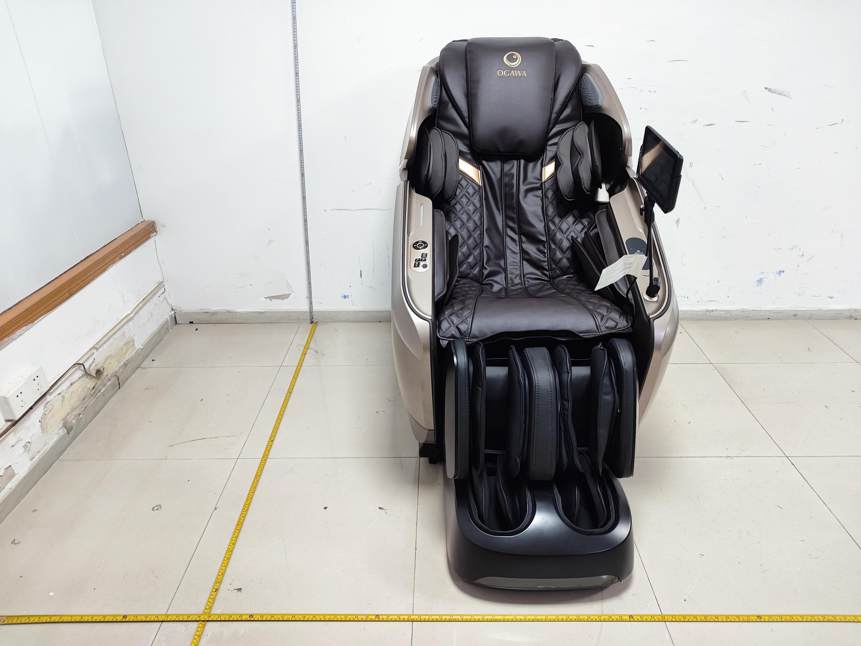
YMX-EC8610M
Jul 14, 2026Massage Chair
Equipment Class
DCD - Part 15 Low Power Transmitter Below 1705 kHz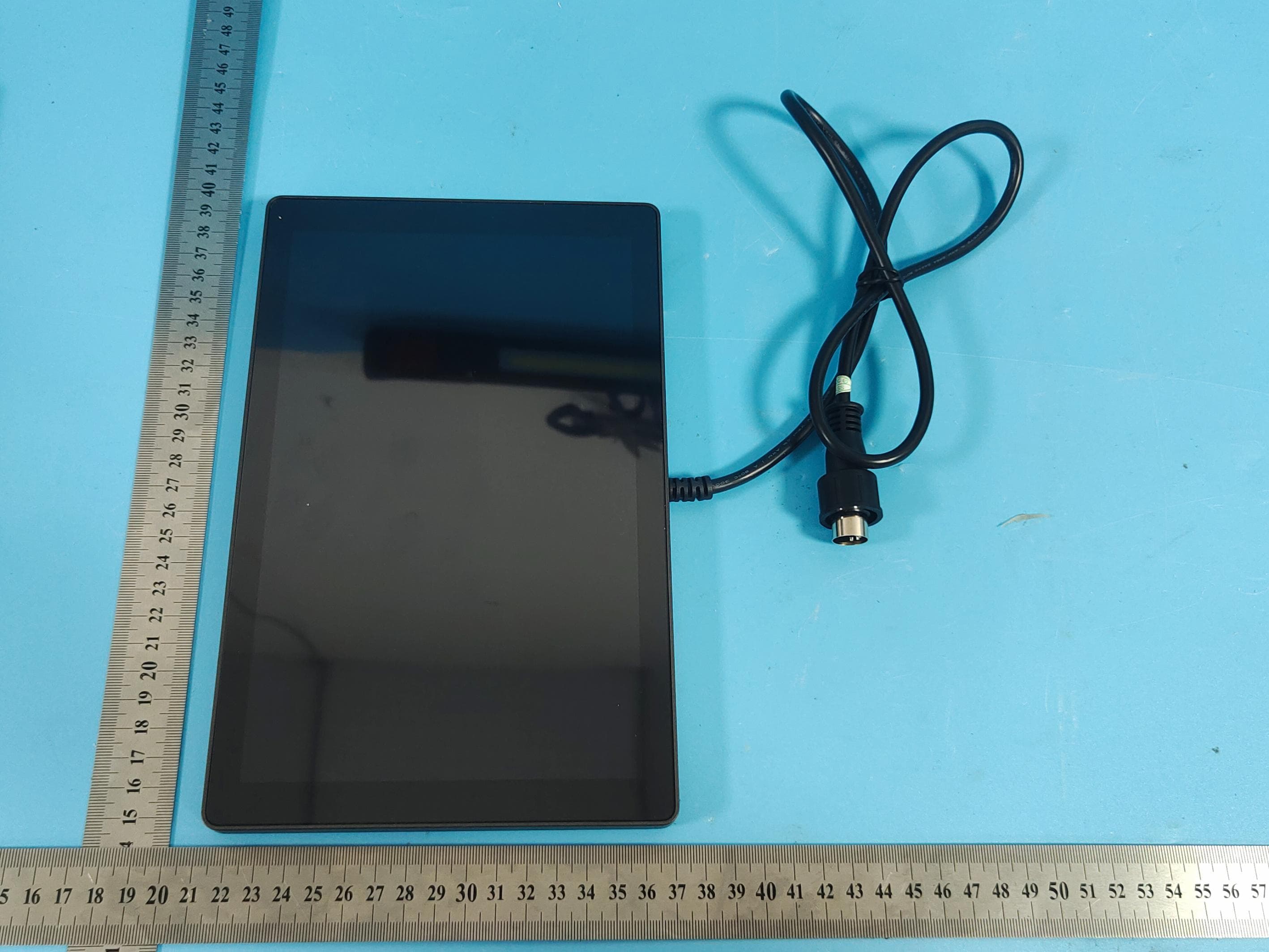
YMX-KP05
Jul 13, 2026KP05 controller
Equipment Class
DSS - Part 15 Spread Spectrum Transmitter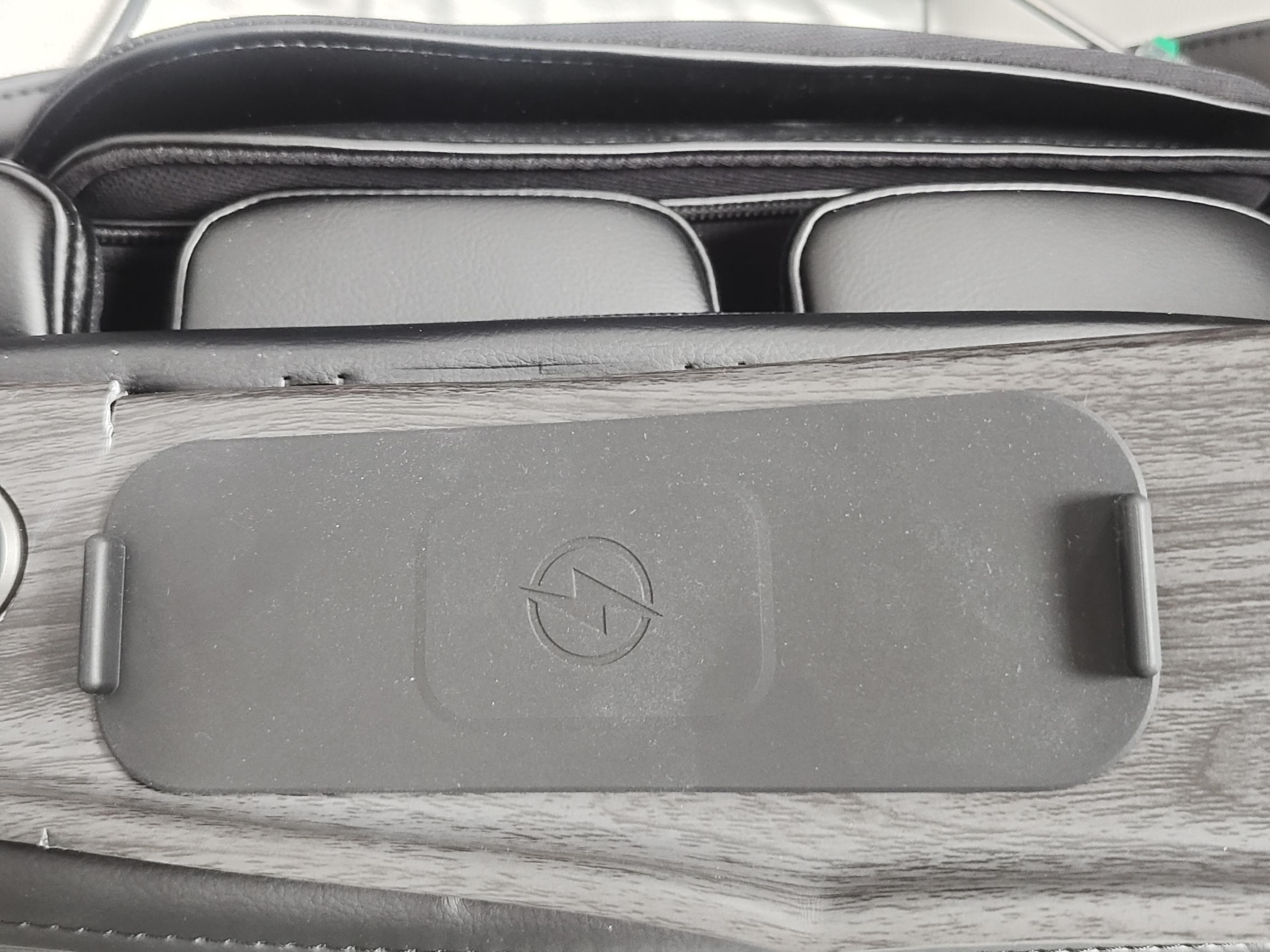
YMX-EC6701B
Mar 23, 2026Massage Chair
Equipment Class
DCD - Part 15 Low Power Transmitter Below 1705 kHz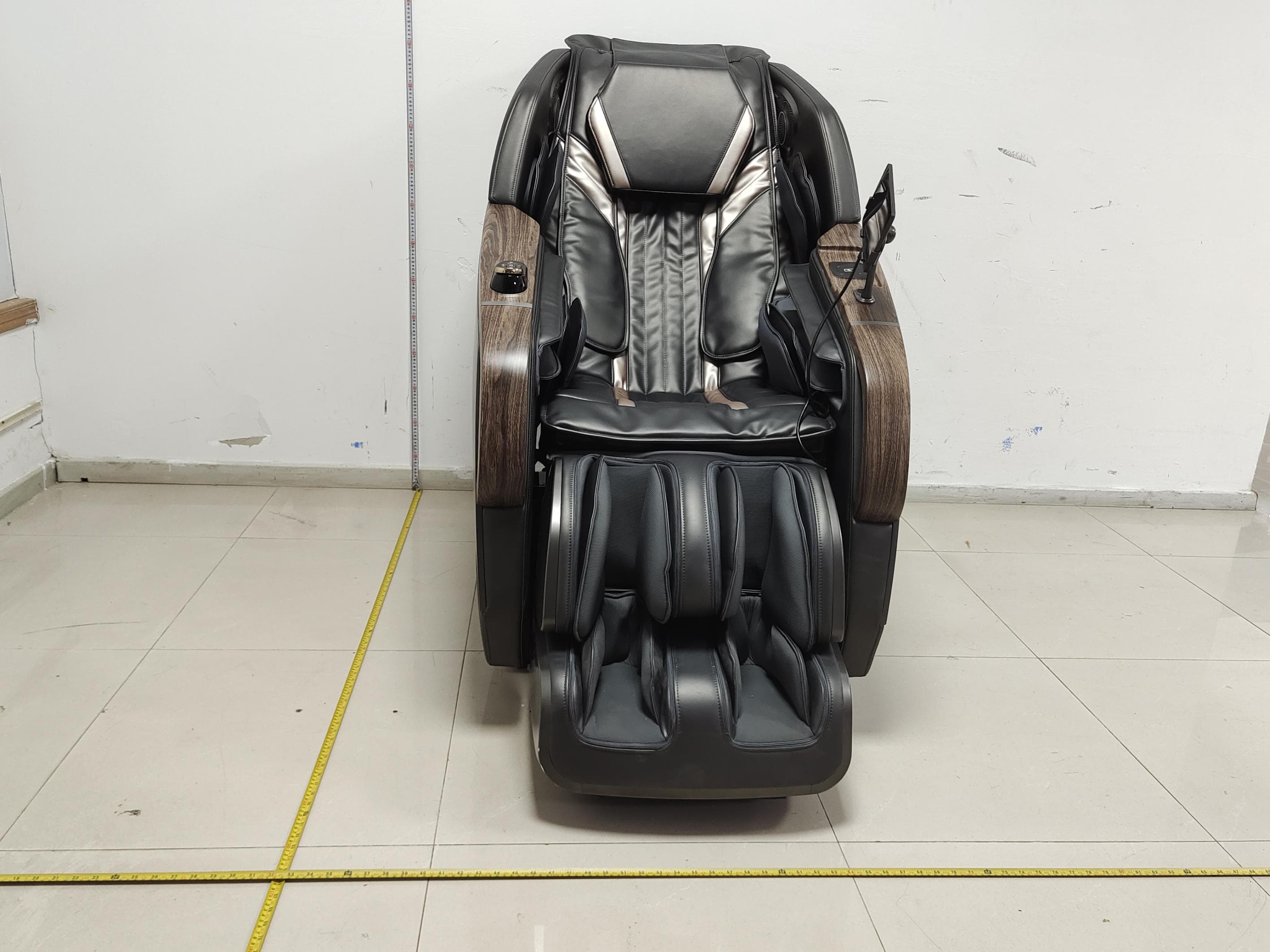
YMX-EC6706A
Feb 05, 2026Massage Chair
Equipment Class
DCD - Part 15 Low Power Transmitter Below 1705 kHz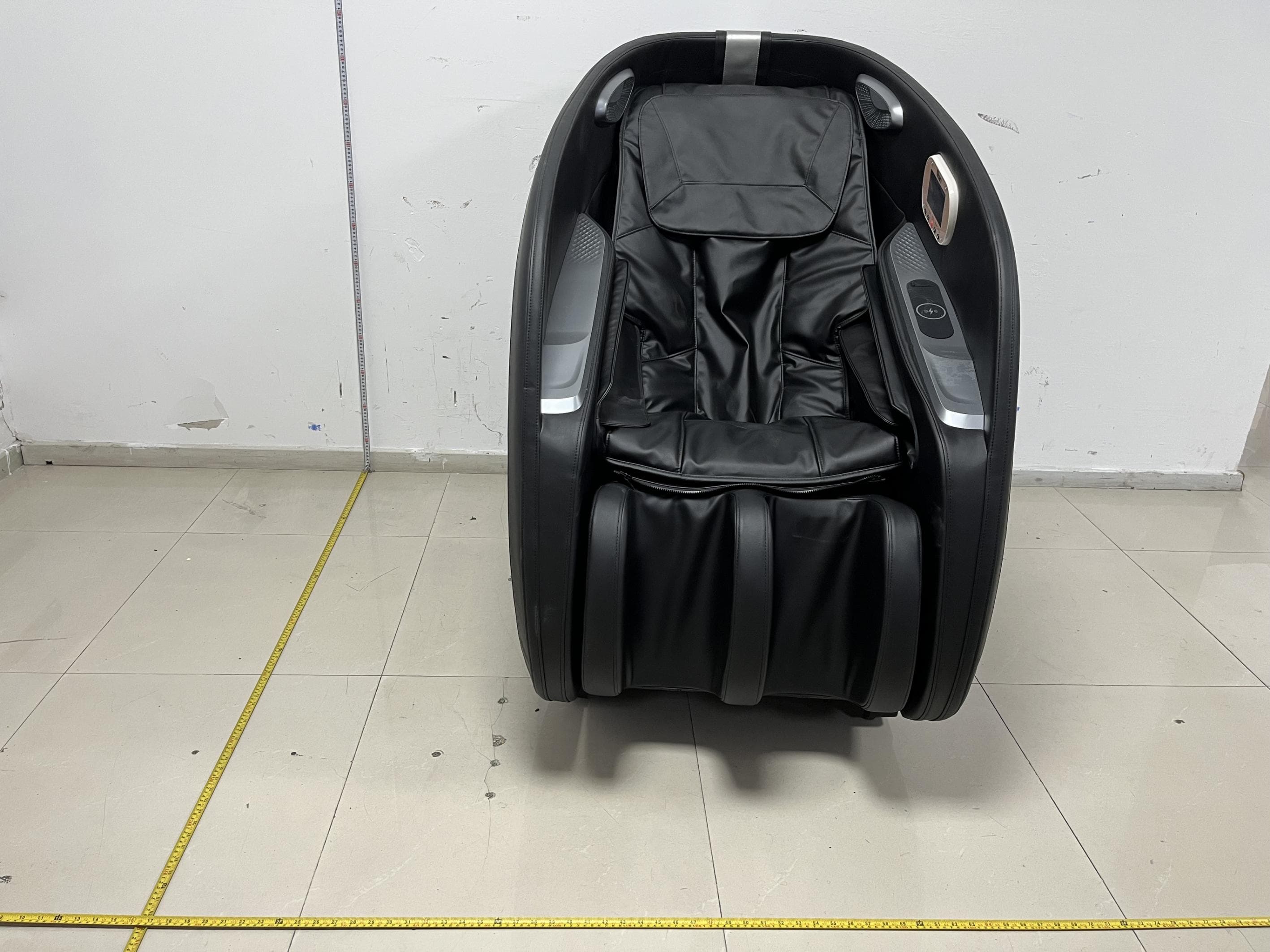
YMX-ES3218D1
Jan 19, 2026Vending Chair
Equipment Class
DCD - Part 15 Low Power Transmitter Below 1705 kHz