YMX-EC802TMassage Chair
XIAMEN COMFORT SCIENCE & TECHNOLOGY GROUP CO., LTD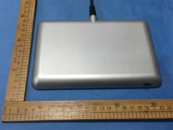
Click to zoom
Application Details
- Equipment Class
- DSS - Part 15 Spread Spectrum Transmitter
- Date of Grant
- May 24, 2020
- Application Purpose
- Original Equipment
- Date of Application
- May 24, 2020
- Equipment Note
- Massage Chair
- Frequency Range
- 2402.00000000 - 2480.00000000
- Country
- China
Documents & Files
Document Text
Text extracted from the exhibit documents filed with the FCC. Open a document above to read the original.
Users Manual
USER MANUAL OG-7010 OG-7010 Hello. 1 Congratulations on purchasing your new Ogawa OG-7010. At Ogawa we understand every body is different and have carefully designed on our massage chair with that in mind. But enough about us, this is about you. Learning how to use your new chair is simple (we designed it that way). So let’s get started. 2 CHAIR MASSAGE INTRO CARE TABLE OF CONTENTS Dimensions Contents Move & Clearance Components Massage Points Specification Interface Pre-Programed Massage Pre-Programed Description Safety 3 4 5 6 7 8 9-10 11-30 31-34 35-36 Grounding Instruction 38 FCC 37 Troubleshooting 38 Care and Storage 38 Warranty 39 Make sure your door is wider than 36” for the chair to pass through without disassembly Door width has to be wider than 32” 32” 52.4” 30.1” 27.2” 53.8” 30.1” 22.7” 28.8” 13.2” 36” 50.4” 51.2” 32.7” DIMENSIONS First, let’s get your chair inside. Seat Base 1 Backrest 2 Side Panels 3 Box Box Box 3 USER MANUAL OG-7010 OG-7010 4 CONTENTS OG-7010 MASSAGE CHAIR Tablet RemotePower Cord Everything you need for a relaxing experience. User ManualInstallation ManualWarranty Postcard OG-7010 OG-7010 OG-7010 5 Move & Clearance Reserve space on left and right Reserve space in the front and back 8” 8” 31.5” 31.5” CLEARANCE HOW TO MOVE Lift and hold the bottom of the chairOne person lift footrest 45 Degrees onto wheels A few simple steps to find the best place for your new chair. 6 CHAIR COMPONENTS Note: The speaker will only operate when the massage chair is in operation Some of your chair’s most important features. LED + Speaker Shoulder Panel Wired Tablet Holder Handrest Backrest Side Panel Wheel Pillow Seat Pad Calf Rest Footrest To play music using your massage chair’s speakers please connect your smartphone, tablet, or other electronic device to your chair using bluetooth 7 MASSAGE POINTS 24 Air Bags 2 Heating Pads 24 Air Bags 2 Rollers Back Massage ModeAir BagHeating PadRoller 8 CHAIR SPECIFICATIONS Power Consumption 120W Max. Ti me Rate 30 minutes Shipping Weight Gross weight: 310.2 lbs Net Weight: 250.8 lbs Safety Feature Equipped with overh eat ing and power su rg e detectors safety fe at ure Di mensions (L x W x H) Chair Dimension: 51.2" x 32.7" x 50.4" Reclined Dimension: 72.8" x 32.7" x 40.6" A few important facts about your massage chair. Rated Voltag e 110 - 120V Rated Frequency 60Hz Power of Speakers 2 x 7W2 sides Length of Wiring Controller wiring 59.1” Power supply wiring 70.9” Usage Condition Enviro nment temperat ure: 10 C-40 C Contrasting humidity: 30-85RH Storage Condition Storage tempera ture : -20 C-60 C Storage humidity level: 30-85RH Model No. OG-7010 OG-7010 9 WIRED TABLET INTERFACE We have designed your massage chair’s tablet controller with a user-friendly interface to make using your chair even easier. Home Screen Pre-Programed Massage Setting Manual Custom Massage MANUALCUSTOMSETTING MASSAGE 10 Massage Controls Name Of Program Time Left Power Strength Intensity Light Color Variation HeatFoot Roller Chair Angle Adjust 11 PRE-PROGRAMED MASSAGE We have designed your chair with multiple massage options for your changing needs. Follow these simple instructions to begin a new pre-programed massage. Choose the "Massage" icon to select your pre-programed massage 12 Choose 1 of our 11 pre-programed massages 13 Pre-Programed Massage Interface 14 Using the arrows, you can adjust the standard shoulder position Adjust Chair Angle Interface 15 Fast adjust chair angle by ZERO GRAVITY 1, ZERO GRAVITY 2, and HOME buttons 16 You can choose manual massage action and compression in this program. Choose the “Manual” icon to begin manual massage MANUAL 17 Choose the "Massage Action" icon 18 Massage Action Interface The knead, tap, clap, and shiatsu massages can be combined with swedish or roll 19 Choose the "Compression" button 20 Compression Interface Choose the “Custom” icon to begin creating your massage program 21 CUSTOM MASSAGE Every body is different. That’s why we’ve given you the option to customize your own massage to meet your specific needs. Follow these simple instructions to create a new custom massage. You can create up to 3 custom programs. To delete a custom massage, press and hold the custom icon and press “delete”. Choose the “Create New” icon 22 23 Select your massage area 24 Select your favorite massage actions. The knead, tap, clap, and shiatsu massages can be combined with swedish or roll 25 SETTINGS Choose the “Setting” button to take you to the settings page 26 Settings Interface Timer AdjustLanguage Adjust Screen Brightness Adjust Screen Sleep Time Adjust Touch Sound Adjust Trouble Shoot Detecting Button 27 Trouble Shooting If your chair has any trouble, press the Trouble Shoot "Start" button for the chair to automatically detect problem areas, and then you can use this information when you contact our customer service team 28 Choose "Start" button and make sure the chair is not occupied during chair detection 29 Your chair is detecting possible malfunctions, please wait for the detection result 30 You can use your detection code when contacting the Ogawa customer team about your chair’s problems 31 PRE-PROGRAMED DESCRIPTION DEMO INTENSITY KNEAD FOCUS TECHNIQUEFOCUS AREA A 5 minute whole body massage for those on the go. GENTLE INTENSITY TAP FOCUS TECHNIQUEFOCUS AREA INTENSITYFOCUS TECHNIQUEFOCUS AREA INTENSITYFOCUS TECHNIQUEFOCUS AREA RELAX KNEAD Let’s dig a little deeper and discover the details of our pre-programed massages. ROLL SHIATSU SWEDISH A program designed to provide a quiet, gentle massage that is good for beginners or those that prefer a soft touch. A program designed to provide a mild massage that is great for deep relaxation, best used before going to sleep. 32 TAPKNEAD SWEDISH THERAPY INTENSITY KNEAD CLAP CLAP FOCUS TECHNIQUEFOCUS AREA VIGOROUS INTENSITYFOCUS TECHNIQUEFOCUS AREAINTENSITYFOCUS TECHNIQUEFOCUS AREA INTENSITYFOCUS TECHNIQUEFOCUS AREA SWEDISH A program designed for those who enjoy a strong deep tissue massage a…
Text truncated - open the document above for the full version.
Attestation Statements
XIAMEN COMFORT SCIENCE & TECHNOLOGY GROUP CO., LTD. Date: 2020-05-18 Statement Product Description: Massage Chair Model name: EC-802T, OG-7010 FCC ID: YMX-EC802T We hereby state that these models are identical in interior structure, electrical circuits and components, and just model number is different for the marketing requirement. Your assistance on this matter is highly appreciated. Sincerely, Name: Pengfei Cui Date: 2020-5-08 Title: Safety Manager Signature of applicant:
Cover Letter(s)
C5266091_X8_Ed.1 1/1 Letter of Authorization XIAMEN COMFORT SCIENCE & TECHNOLOGY GROUP CO., LTD. Company: XIAMEN COMFORT SCIENCE & TECHNOLOGY GROUP CO., LTD. Address: (5/F) NO.168, QIANPU ROAD SIMING DISTRICT, XIAMEN, CHINA. Product Name: Massage Chair Model Number: EC-802T, OG-7010 FCC Identifier: YMX-EC802T We authorize LGAI Technological Center S.A., Ronda de la Font del Carme, s/n, 08193 Bellaterra, Spain, to act on our behalf on all matters concerning the above named equipment. Any individual within LGAI Technological Center S.A. is authorized to act on our behalf and take action on the application. We declare that authorize LGAI Technological Center S.A., Ronda de la Font del Carme, s/n, 08193 Bellaterra, Spain, is allowed to forward all information related to the approval project to the Federal Communication Commission and to discuss any issues concerning the approval application. Any and all acts carried out by LGAI Technological Center S.A. on our behalf shall have the same effect as acts of our own. Name: Pengfei Cui Date: 2020-5-08 Title: Safety Manager Signature of applicant:
Cover Letter(s)
C5266091_X10_Ed.1 1/1 XIAMEN COMFORT SCIENCE & TECHNOLOGY GROUP CO., LTD. Office of Engineering Technology Federal Communications Commission 7435 Oakland Mills Road Columbia, MD 21046 Date: May 08, 2020 Subject: Request for Confidentiality FCC ID: YMX-EC802T To Whom It May Concern, Pursuant to the provisions of Sections 0.457 and 0.459 of Commission's rules (47CFR0.457, 0.459), we are requesting the Commission to withhold the following attachment(s) as confidential document from public disclosure. Exhibits Long-Term Confidentiality Short-Term Confidentiality ID Label/Location No No Attestation Statement No No External Photos Block Diagram Schematics Test Report No No Test Setup Photos No No User’s Manual No No Internal Photos Parts List / Tune Up No No RF Exposure Info No No Operational Description No Cover Letter(s) No No SDR Software / Security Info No No Above mentioned document contains detailed system and equipment description are considered as proprietary information in operation of the equipment. The public disclosure of above documents might be harmful to our company and would give competitor an unfair advantage in the market. It is our understanding that all measurement test reports, FCC ID label format and correspondent during certification review process cannot be granted as confidential documents and those information will be available for public review once the grant of equipment authorization is issued. Sincerely, Name: Pengfei Cui Date: 2020-5-08 Title: Safety Manager Signature of applicant:
External Photos
External photo FCC ID: YMX-EC802T
ID Label/Location Info
Label and label location EC-802T can be replaced by model OG-7010
Internal Photos
FCC ID: YMX-EC802T PCB Antenna
RF Exposure Info
FCC ID : YMX-EC802T Portable device According to §15.247(e)(i) and §1.1307(b)(1), systems operating under the provisions of this section shall be operated in a manner that ensures that the public is not exposed to radio frequency energy level in excess of the Commission’s guidelines. According to KDB 447498 D01 General RF Exposure Guidance v06, section 4.3.1 The 1-g and 10-g SAR test exclusion thresholds for 100 MHz to 6 GHz at test separation distances ≤ 50 mm are determined by: [(max. power of channel, including tune-up tolerance, mW)/(min. test separation distance, mm)] · [√f(GHz)] ≤ 3.0 for 1-g SAR and ≤ 7.5 for 10-g extremity SAR, 16 where f(GHz) is the RF channel transmit frequency in GHz Power and distance are rounded to the nearest mW and mm before calculation 17 The result is rounded to one decimal place for comparison The test exclusions are applicable only when the minimum test separation distance is ≤ 50 mm and for transmission frequencies between 100 MHz and 6 GHz. When the minimum test separation distance is < 5 mm, a distance of 5 mm is applied to determine SAR test exclusion. Max Antenna Gain = 2dBi GFSK mode (Worse case) Frequency (MHz) Output Power (dBm) Target power (dBm) Target power (mW) Calculation Value Threshold Value 2402 -0.99 0±1 1.259 0.39 3.0 2441 -0.32 0±1 1.259 0.39 3.0 2480 -0.07 0±1 1.259 0.40 3.0 Threshold at which no SAR required is ≤ 3.0 for 1-g SAR, Separation distance is 5mm. Conclusion: No SAR is required. SIMULTANEOUS TRANSMISSION EVALUATION N/A
Test Report
Report No.: ATE20200296 Page 1 of 85 FCC ID: YMX-EC802T Shenzhen Accurate Technology Co., Ltd. APPLICATION CERTIFICATION FCC Part 15C On Behalf of XIAMEN COMFORT SCIENCE & TECHNOLOGY GROUP CO., LTD. Massage Chair Model No.: EC-802T, OG-7010 FCC ID: YMX-EC802T Prepared for : XIAMEN COMFORT SCIENCE & TECHNOLOGY GROUP CO., LTD. Address : (5/F) NO.168, QIANPU ROAD SIMING DISTRICT, XIAMEN, CHINA. Prepared by : Shenzhen Accurate Technology Co., Ltd. Address : 1/F., Building A, Changyuan New Material Port, Science & Industry Park, Nanshan District, Shenzhen, Guangdong, P.R. China. Tel: (0755) 26503290 Fax: (0755) 26503396 Report No. : ATE20200296 Date of Test : April 04, 2020-May 20, 2020 Date of Report : May 22, 2020 Report No.: ATE20200296 Page 2 of 85 FCC ID: YMX-EC802T Shenzhen Accurate Technology Co., Ltd. TABLE OF CONTENTS Description Page Test Report Certification 1. GENERAL INFORMATION .......................................................................................................... 5 1.1. Description of Device (EUT) ................................................................................................................. 5 1.2. Model difference declaration ................................................................................................................ 5 1.3. Accessory and Auxiliary Equipment .................................................................................................... 6 1.4. Description of Test Facility ................................................................................................................... 6 1.5. Measurement Uncertainty ..................................................................................................................... 7 2. MEASURING DEVICE AND TEST EQUIPMENT ..................................................................... 8 3. OPERATION OF EUT DURING TESTING ................................................................................. 9 3.1. Operating Mode ........................................................................................................................................ 9 3.2. Configuration and peripherals .................................................................................................................. 9 4. TEST PROCEDURES AND RESULTS ....................................................................................... 10 5. 20DB BANDWIDTH TEST ............................................................................................................ 11 5.1. Block Diagram of Test Setup .................................................................................................................. 11 5.2. The Requirement For Section 15.247(a)(1) ............................................................................................ 11 5.3. EUT Configuration on Measurement ..................................................................................................... 11 5.4. Operating Condition of EUT .................................................................................................................. 11 5.5. Test Procedure ........................................................................................................................................ 11 5.6. Test Result .............................................................................................................................................. 12 6. CARRIER FREQUENCY SEPARATION TEST ........................................................................ 18 6.1. Block Diagram of Test Setup .................................................................................................................. 18 6.2. The Requirement For Section 15.247(a)(1) ............................................................................................ 18 6.3. EUT Configuration on Measurement ..................................................................................................... 18 6.4. Operating Condition of EUT .................................................................................................................. 18 6.5. Test Procedure ........................................................................................................................................ 19 6.6. Test Result .............................................................................................................................................. 19 7. NUMBER OF HOPPING FREQUENCY TEST ......................................................................... 25 7.1. Block Diagram of Test Setup .................................................................................................................. 25 7.2. The Requirement For Section 15.247(a)(1)(iii) ...................................................................................... 25 7.3. EUT Configuration on Measurement ..................................................................................................... 25 7.4. Operating Condition of EUT .................................................................................................................. 25 7.5. Test Procedure ........................................................................................................................................ 25 7.6. Test Result .............................................................................................................................................. 26 8. DWELL TIME TEST ..................................................................................................................... 28 8.1. Block Diagram of Test Setup .................................................................................................................. 28 8.2. The Requirement For Section 15.247(a)(1)(iii) ...................................................................................... 28 8.3. EUT Configuration on Measurement ..............................…
Text truncated - open the document above for the full version.
Test Setup Photos
FCC ID: YMX-EC802T Photograph of set-up for Radiated Emission below 1GHz Photograph of set-up for Radiated Emission above 1GHz Photograph of set-up for conducted Emission
Contact Information
Applicant
Pengfei Cui(Safety Engineer)
Technical Contact
XIAMEN COMFORT SCIENCE & TECHNOLOGY GROUP CO., LTDPengfei Cui
[email protected]86-592-7266925
XIAMEN · China
Test Firm
Shenzhen Accurate Technology Co., Ltd.Lisa Zhang
[email protected]+86-755-26503290
Technical Specifications
| # | Rule Parts | Frequency Range | Power Output |
|---|---|---|---|
| 1 | 15C | 2.40 GHz - 2.48 GHz | 984.00 µW |
Other Applications from XIAMEN COMFORT SCIENCE & TECHNOLOGY GROUP CO., LTD
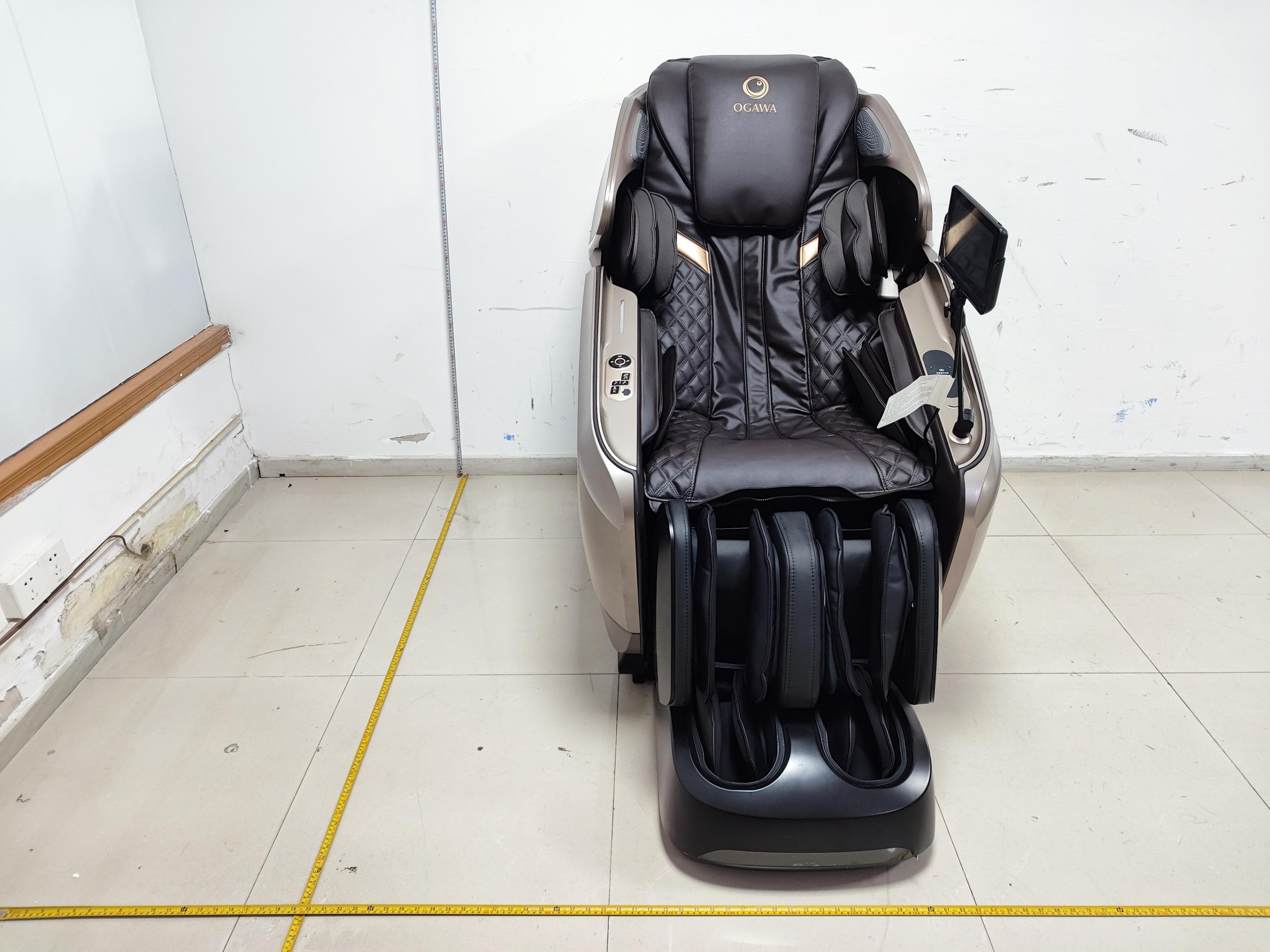
YMX-EC8610M
Jul 14, 2026Massage Chair
Equipment Class
DCD - Part 15 Low Power Transmitter Below 1705 kHz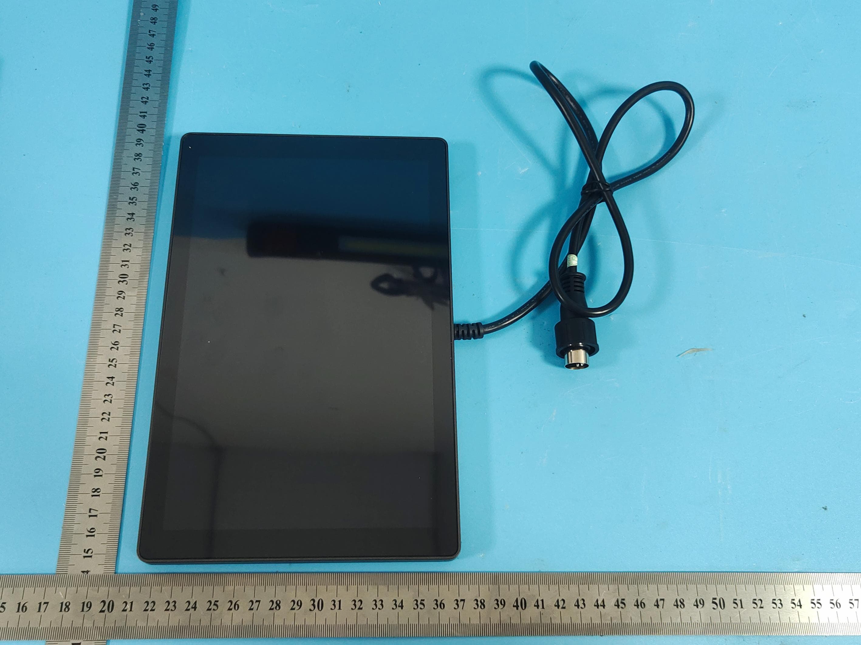
YMX-KP05
Jul 13, 2026KP05 controller
Equipment Class
DSS - Part 15 Spread Spectrum Transmitter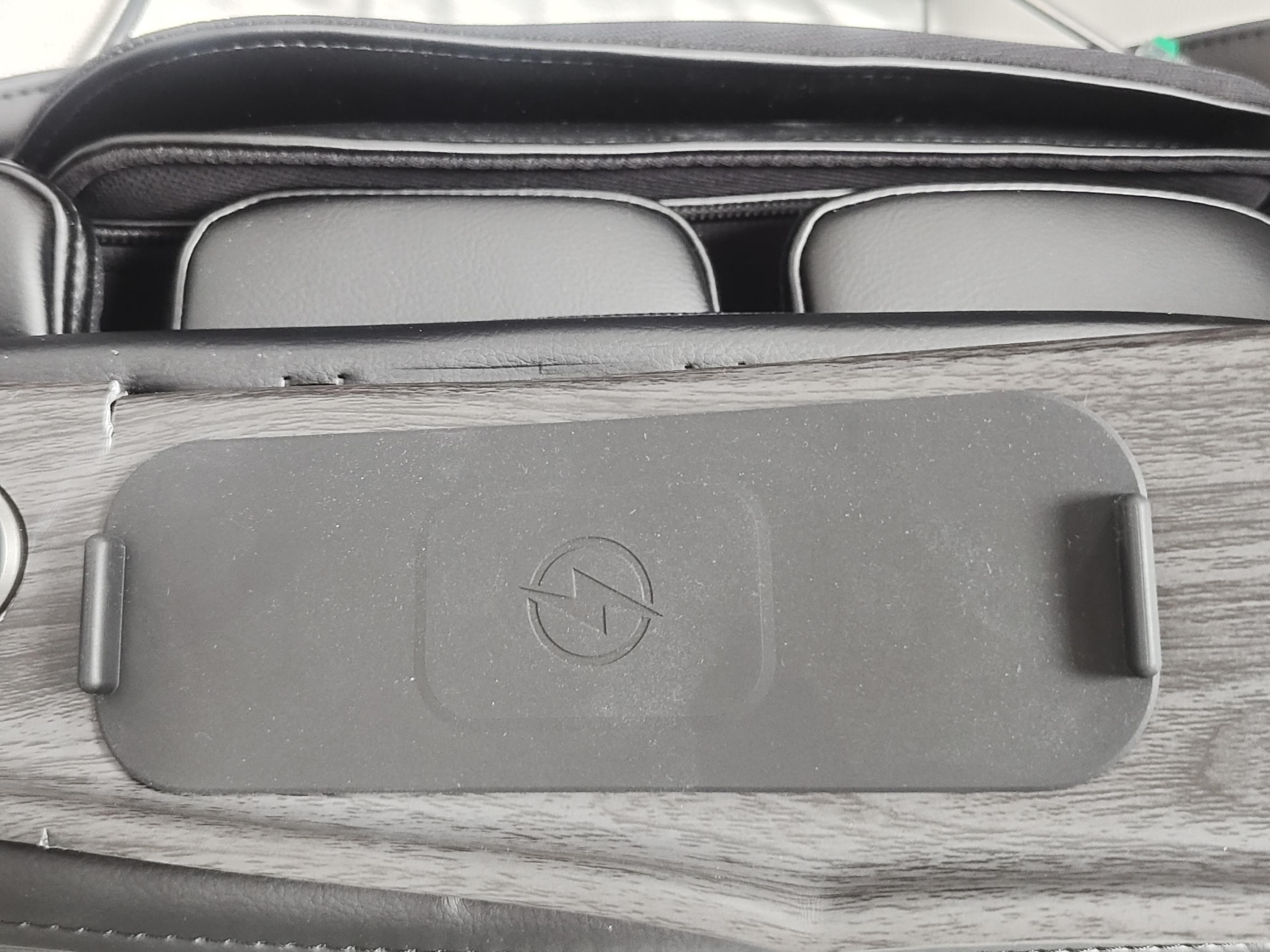
YMX-EC6701B
Mar 23, 2026Massage Chair
Equipment Class
DCD - Part 15 Low Power Transmitter Below 1705 kHz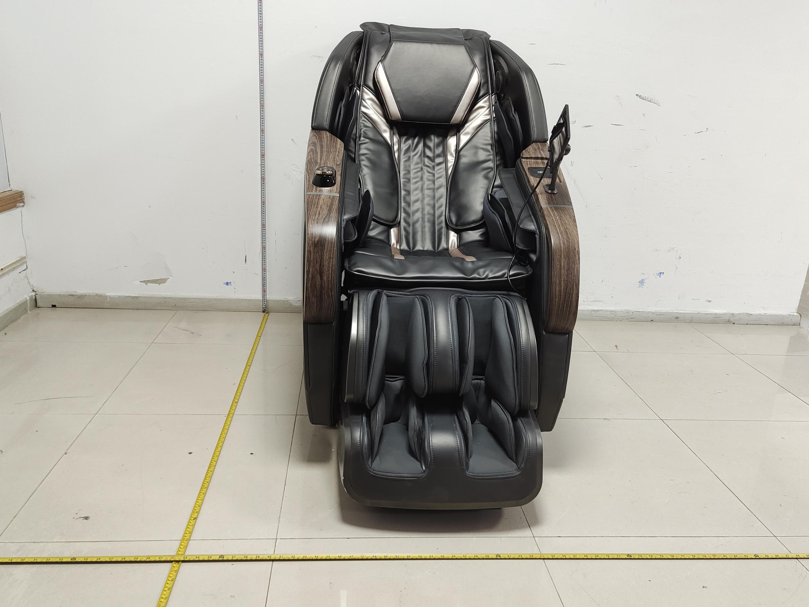
YMX-EC6706A
Feb 05, 2026Massage Chair
Equipment Class
DCD - Part 15 Low Power Transmitter Below 1705 kHz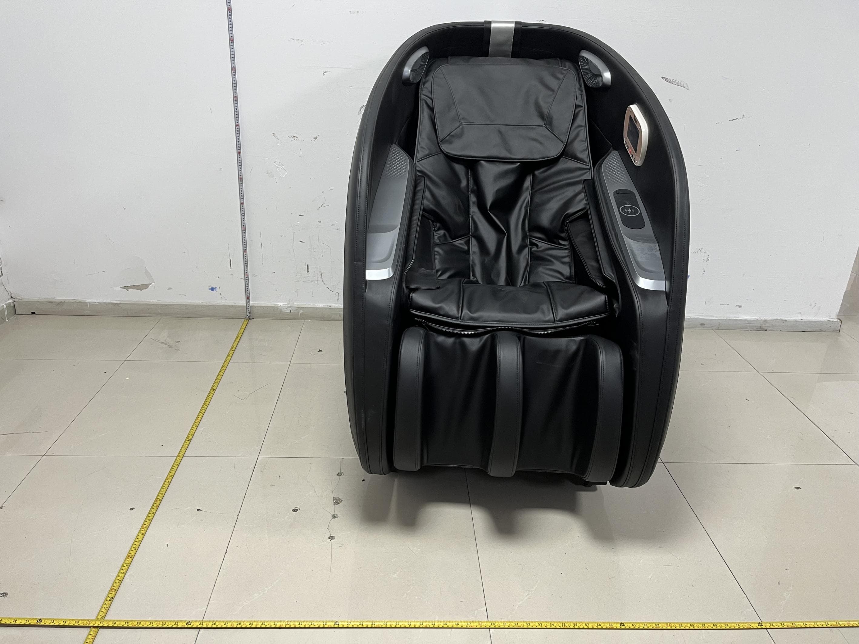
YMX-ES3218D1
Jan 19, 2026Vending Chair
Equipment Class
DCD - Part 15 Low Power Transmitter Below 1705 kHz