YN4PE501CAR ALARM
INTELLIGENCE UNI-ID (SHENZHEN) INC.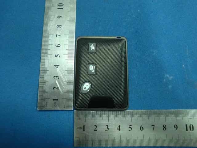
Click to zoom
Application Details
- Equipment Class
- DSC - Part 15 Security/Remote Control Transmitter
- Date of Grant
- Oct 10, 2010
- Application Purpose
- Original Equipment
- Date of Application
- Oct 10, 2010
- Equipment Note
- CAR ALARM
- Frequency Range
- 433.92000000 - 433.92000000
- Country
- China
Documents & Files
Document Text
Text extracted from the exhibit documents filed with the FCC. Open a document above to read the original.
Users Manual
1 ONE-WAY AUTOMATIC / MANUAL TRANSMISSION REMOTE STARTER WITH FULL ALARM SYSTEM Introduction This Module is a state-of-the-art combination of an Alarm system and a remote car starter. It represents a major breakthrough in vehicle security technology and remote starter systems. This unit is distributed with a super-heterodyne antenna with range of up to 30 m. Vehicle Presets Heater & Heated Seat When leaving the vehicle it is recommended to preset the accessory controls in preparation for the next remote start. Settings for the blower motor (fan), front and rear, as well as heated seats (if equipped) should not be left on High. It is recommended to leave the settings on Low or Medium instead. Windshield Wipers & Radio & Headlights Certain vehicles require the radio and / or windshield wiper and / or headlight circuits to become energized while running under remote start. When leaving the vehicle you must ensure that the windshield wiper and headlight switches are Off. Leaving the headlight switch on on certain vehicles could cause them to remain ON even after remote starter shut down, resulting in a dead battery. Using the remote control This system is equipped with a 3-button multi-channel transmitter. The functions of the transmitter are as follows: LOCK : Locks the doors and arms the STARTER KILL. Triggers Panic if pressed more than 3 seconds UNLOCK : Unlocks the doors and disarms the STARTER KILL. Triggers opening the TRUNK if pressed more than 3 seconds. START : Remote starts or stops the engine if pressed for 2 seconds. Remote starting your vehicule Remotestarting Press the button for approximately 2 second. The parking lights will turn flash once to inform you that the Remote Car Starter has received your signal. Approximately 5 seconds later, the engine will start. The parking lights will remain ON during the pre-programmed run time of the engine. If your vehicle has an automatic transmission and it does not start at the first attempt, the system will shut down, wait a few seconds and try to start the engine again. There will be 3 start attempts before the system gives up. Driving Off With the vehicle running under remote control, press the button to disarm and unlock the doors. Enter the vehicle and do the following: Turn the ignition key to the IGNITION ON (RUN) position. (Do not turn the key to the CRANK position while the engine is running. This would cause the starter motor to re-engage.) Press the brake pedal to disengage the remote starter unit. You are now ready to drive off. Arming and disarming of the System The Alarm can be configured by the installer either to Passive Mode (so as to arm automatically) or Active Mode (so as to require the user’s intervention for arming). By default, the Remote Car Starter is configured to Passive Mode Passive mode: To arm the alarm, press the button on the transmitter, OR 1. In Passive Mode, the alarm will automatically arm 30sec once the last door is closed. 2. The LED on the antenna will flash quickly during the countdown preceding the activation of the system. 3. Once the activation countdown expires, the LED will flash slowly to indicate that the alarm is now armed. 2 To disarm the alarm, press the button on the transmitter. 1. The LED on the antenna will flash quickly during the countdown preceding the activation of the system. 2. The alarm will automatically rearm itself after 30sec if no door is left opened (if the doors are monitored) and the ignition is not turned ON. Active Mode: To arm the alarm, press the button on the transmitter. 1. The siren will chirp once. 2. The LED on the antenna will flash slowly. To disarm the Alarm, press the button on the transmitter. 1. The siren will chirp twice. 2. The LED on the antenna will remain OFF. Remote starter features Remote Door Locks If your system was installed with the Remote Door Locks option, you will have the convenience of remote keyless entry. To UNLOCK your doors and DISARM the system: 1. Press and hold the button for approx. 1 sec. 2. The siren will chirp twice to confirm that the doors have been unlocked, the Starter Kill feature is disarmed (if it was installed) and that the Alarm is disabled. To LOCK your doors and ARM the system: 1. Press and hold the button for approx. 1 sec. 2. The siren will chirp once to confirm that the doors have been locked, the Starter Kill feature is enabled (if it was installed) and that the Alarm is armed. Remote Trunk Release If your system was installed with the Remote Trunk Release option, you can open your trunk by pressing the button for 3 seconds on the remote transmitter. In addition, this will also disarm the system. Panic Mode In an emergency situation, you can activate panic mode by pressing and holding the button , for more than 3 seconds, until the siren starts to sound. If the vehicle is under a remote start, the engine will shutdown automatically before setting off the Siren. You can stop the Siren by pressing: (this will lock your doors and deactivate panic mode), or (this will unlock your doors and deactivate panic mode). * Panic Mode will automatically shut down after 30sec. Advance Features: The system was designed with flexibility and OEM integration in mind. With its programmable options, this unit can single-handedly control nearly any electrical system in your vehicle. Note: The programming of your system should be left to a professional. Changing any one of the settings may affect the operation of your system. Ignition-controlled Door Locks This is an added security feature. If your Remote Car Starter was installed with the Ignition-Controlled Door Locks option, the doors will automatically lock as soon as the ignition key is turned to the IGNITION ON (RUN) position while the brakes are pressed. The remote car starter will also lock any door that was unlocked and opened (then closed) the next time the break pedal is pressed. When the key is turned to the OFF position, the doors will automatically be unlocked. Engine Run…
Text truncated - open the document above for the full version.
Block Diagram
Keys MCU Encoder UHF TX Module 433.92MHz Crystal oscillator 40.03MHz
External Photos
External Photo For modle: PE501, PE502, PE503, PE504, PE505, PE506, PE507, PE508, PE401, PE402 External Photo For modle: PE501, PE502, PE503, PE504, PE505, PE506, PE507, PE508, PE401, PE402
ID Label/Location Info
FCC ID LABEL FCC ID:YN4PE501 This device complies with Part 15 of the FCC Rules.Operation is subject to the following two conditions:1. This device may not cause harmful interference, and 2. This device must accept any interference received,including interference that may cause undesired operation. Label Location on EUT EUT Bottom View/ FCC ID Label Location
Internal Photos
Internal Photo For modle: PE501, PE502, PE503, PE504, PE505, PE506, PE507, PE508, PE401, PE402 Internal Photo For modle: PE501, PE502, PE503, PE504, PE505, PE506, PE507, PE508, PE401, PE402 Internal Photo For modle: PE501, PE502, PE503, PE504, PE505, PE506, PE507, PE508, PE401, PE402 Internal Photo For modle: PE501, PE502, PE503, PE504, PE505, PE506, PE507, PE508, PE401, PE402 Antenna
Operational Description
Description 1. Normal conditions, The car remote controls was dormant 2. After pressing the button, The remote control was aroused immediately, And then determine which button is pressed 3. According to press a key definition, The corresponding eight bytes data into a buffer, Ready to launch by a module of UHF transmitting 4.UHF transmitter module use 433.92MHz saw resonator and other RF circuit 5.The alarm received data from the remote control, Validated according to the request made codes to make the appropriate action
Schematics
55 44 33 22 11 D D C C B B A A 86 15 2 4 WDEEN WDEENRF2 RF3 RF1 RF2 RF3 RF1 UHF_DATA WDEEN PGD VPP_SW3 PGC WAKE EOBA TENTDAT TCLK VCL VCL SW1 PGCPGD VPP_SW3 TDATTENVCLTCLK WAKE SW1 SW2 WAKE WDEEN VPP_SW3 LED1 SW2 LED1 BATLevel UHF_DATA EOBA BATLevel +3V +3V +3V +3V +3V +3V +3V +3V +3V TitleSize Document Number Rev Date: Sheet of PETRSCH5V10(PCB: 407-1069 V1.0) 1.0 Transmitter (433.92MHz) A 11 Thursday, July 22, 2010 TitleSize Document Number Rev Date: Sheet of PETRSCH5V10(PCB: 407-1069 V1.0) 1.0 Transmitter (433.92MHz) A 11 Thursday, July 22, 2010 TitleSize Document Number Rev Date: Sheet of PETRSCH5V10(PCB: 407-1069 V1.0) 1.0 Transmitter (433.92MHz) A 11 Thursday, July 22, 2010 UNLOCK LOCK RST C3 100pF/50V C3 100pF/50V U2TMS37127U2TMS37127 GND 1 VCCO 2 RF3 3 TDAT 4 TEN 5 VBAT 6 EOBA 7 CLKA/M 8 WAKE 9 WDEEN 10 TX 11 MOD 12 TCLK 13 RF2 14 RF1 15 VCL 16 R8 1KR8 1K SW3 TS-032 SW3 TS-032 13 24 U3 NCP803SN232T1(SQR) U3 NCP803SN232T1(SQR) OUT 2 GND 1 VCC 3 C4 100pF/50V C4 100pF/50V C82pF/50VC82pF/50V TP3TP3 1 C96pF/50VC96pF/50V ANT1_LY1 7.2mH ANT1_LY1 7.2mH C10.1uFC10.1uF ANT1_LX1 7.2mH ANT1_LX1 7.2mH R3100R3100 ANT2ANT2 TP1TP1 1 TP2TP2 1 R9 330R9 330 C20.1uFC20.1uF Q2 2SC3356(R25) Q2 2SC3356(R25) 1 32 R4220R4220 U1PIC16F684-I/SLU1PIC16F684-I/SL RA0/AN0 13 RA1/AN1 12 RA2/T0CKI/AN2 11 RA5/T1CKI/OSC1 2 RC4 6 RC3/AN7 7 RC5 5 RC2/AN6 8 RC1/AN5 9 VDD 1 RA4/OSC2 3 RA3/MCLR 4 RC0/AN4 10 VSS 14 J2 HDMI10-1.0 J2 HDMI10-1.0 123456789 10 SW2 TS-032 SW2 TS-032 13 24 TP4TP4 1 R6 1KR6 1K C622nF/50VC622nF/50V R7 82K R7 82K R122KR122K SAW1 NDR4003 SAW1 NDR4003 G4 4 O 3 G2 2 I 1 LED10805BLUELED10805BLUE BT1 CR2032 BT1 CR2032 SW1 TS-032 SW1 TS-032 13 24 C5 100pF/50V C5 100pF/50V ANT1_LZ1 7.2mH ANT1_LZ1 7.2mH C70.1uF/50VC70.1uF/50V R5 1K R5 1K R2 82KR2 82K
Test Report
FCC PART 15.231 EMI MEASUREMENT AND TEST REPORT For INTELLIGENCE UNI-ID (SHENZHEN) INC. Rm. 407, 2nd Park, Shenzhen Longgang Overseas Chinese High-Tech Venture Park, Qinglin Xi Road, Longgang District, Shenzhen FCC ID:YN4PE501 Oct. 08, 2010 This Report Concerns: Original Report Equipment Type Car Alarm Test Engineer: Eric Li Report No.: BST10070446R-3 Receive EUT Date/Test Date: Sep.27,2010/ Sep.27-30,2010 Reviewed By: Christina Deng Prepared By: Shenzhen BST Technology Co.,Ltd. 3F,Weames Technology Building, No. 10 Kefa Road,Science Park, Nanshan District,Shenzhen,Guangdong,China Tel: 0755-267477513 Fax: 0755-267477513 ext.826 Note: The test report is specially limited to the above company and this particular sample only. It may not be duplicated without prior written consent of Shenzhen BST Technology Co.,Ltd. This report must not be used by the client to claim product certification,approval,or endorsement by NVLAP, NIST or any agency of the US Government. INTELLIGENCE UNI-ID (SHENZHEN) INC. FCC ID: YN4PE501 BST FCC ID REPORT : BST10070446R-3 Page 2/15 TABLE OF CONTENTS 1. GENERAL INFORMATION ....................................................................................................3 1.1. Report information ............................................................................................................3 1.2. Measurement Uncertainty .................................................................................................3 2. PRODUCT DESCRIPTION ......................................................................................................4 2.1. EUT Description ...............................................................................................................4 2.2. Block Diagram of EUT Configuration..............................................................................4 2.3. Support Equipment List ....................................................................................................4 2.4. Test Conditions .................................................................................................................4 3. FCC ID LABEL...........................................................................................................................5 4. TEST RESULTS SUMMARY ...................................................................................................6 Modifications ................................................................................................................................6 5. TEST EQUIPMENT USED .......................................................................................................7 6. CONDUCTED POWER LINE TEST .......................................................................................8 6.1. Test Equipment .................................................................................................................8 6.2. Test Procedure ..................................................................................................................8 6.3. Test Setup..........................................................................................................................8 6.4. Configurating of the EUT .................................................................................................8 6.5. EUT Operating Condition ...............................................................................................10 6.6. Conducted Power line Emission Limits..........................................................................10 6.7. Conducted Power Line Test Result.................................................................................10 7. RADIATION EMISSIONS ......................................................................................................11 7.1. Test Equipment ...............................................................................................................11 7.2. Test Procedure ................................................................................................................11 7.3. Radiated Test Setup ........................................................................................................11 7.4. Radiated Emission Limit.................................................................................................11 7.5. Radiated Emission Test Result .......................................................................................12 8. 20B BANDWIDTH....................................................................................................................13 8.1. Test Equipment ...............................................................................................................13 8.2. Test Procedure ................................................................................................................13 8.3. FCC 15.231(c) 20B Bandwidth Limit.............................................................................13 8.4. Test Result ......................................................................................................................13 9. DEACTIVATION TESTING...................................................................................................14 9.1. Test Equipment ...............................................................................................................14 9.2. Test Procedure ................................................................................................................14 9.3. Deactivation Requirement ..............................................................................................14 9.4. Test Result ......................................................................................................................14 10. ANTENNA REQUIREMENT .................................................................................................15 10.1. STANDARD APPLICABLE....................................................................…
Text truncated - open the document above for the full version.
Contact Information
Applicant
Weige Chu(Manager)
Test Firm
emitel (Shenzhen) LimitedLouis Lin
Technical Specifications
| # | Rule Parts | Frequency Range | Power Output |
|---|---|---|---|
| 1 | 15.231 | 433.92 MHz - 433.92 MHz | - |