FCCID.CO- FCC ID Database
HomeCompaniesEquipment ClassesSearch

© 2026 FCC ID Database. All rights reserved.

AboutContactData sourced from FCC public records
  1. Home/
  2. DONGYOUNG Enterprise Co., Ltd./
  3. YN9-HN-WC10P

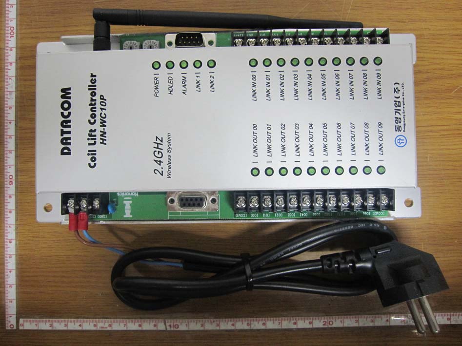
YN9-HN-WC10P10-PORT COIL LIFT SYSTEM

DONGYOUNG Enterprise Co., Ltd.
10-PORT COIL LIFT SYSTEM - FCC ID YN9-HN-WC10P - DONGYOUNG Enterprise Co., Ltd.
Click to zoom

Application Details

Equipment Class
DTS - Digital Transmission System
Date of Grant
Aug 19, 2010
Application Purpose
Original Equipment
Date of Application
Aug 18, 2010
Equipment Note
10-PORT COIL LIFT SYSTEM
Frequency Range
2405.00000000 - 2470.00000000
Company
DONGYOUNG Enterprise Co., Ltd.
Country
South Korea

Documents & Files

Select a file to view
Users Manual

↗

Attestation Statements

↗

Cover Letter(s)

↗
↗

External Photos

↗

ID Label/Location Info

↗

Internal Photos

↗

RF Exposure Info

↗

Test Report

↗
↗

Test Setup Photos

↗

Document Text

Text extracted from the exhibit documents filed with the FCC. Open a document above to read the original.

Users Manual

COIL LIFT SYSTEM User’s Manual [HN-WC10P] 2.4GHz Wireless Relay Data Transmitter/Receiver System 2 Copyright © 2010 All rights reserved designed by DongYoung Enterprise Co., Ltd 1. Introduction It is a system that outputs through wireless communication after receiving inputs of relay contact points of an electronic panel or an external device. It can be used by composing input/output the way operator wants in a form of both direction control as it is designed for both input and output and it can be substituted for D/I. and D/O cards of PLC. A system can be composed by using various product lines (4Port, 8Port, 10Port) according to the numbers of control signal and it can be used by extending up to numbers of contact points that are demanded through the equipped serial port. 2. Cautions before using 1) Be cautious with shock while transporting the product and check for any damages. ( Especially be careful with damage in antenna of transmitter and receiver) 2) Make sure to check if specifications of this product and usage purpose correspond. 3) Perform a communication test in advance and install because the distance of communication can shorten if there are obstacles like concrete structure between the transmitter and the receiver. ( If a communication test is needed, please contact our company beforehand. ) 4) Direction for attaching the product must be horizontal or vertical, and install it by avoiding a location with high surrounding temperature and selecting a place with less electric noise. 5) It requires attention that when input power supply of this product is repetitively ON/OFF , it can cause disoperation of the inner circuit and the operation power must be connected to the front part of an emergency switch in a condition that power is being put always. Data 1 Data 2 Data 3 Data 4 Data 5 Data 6 Data 7 Data 8 Data 9 Data 10 2.4GHz Data 1-1 Data 2-1 Data 3-1 Data 4-1 Data 5-1 Data 6-1 Data 7-1 Data 8-1 Data 9-1 Data 10-1 3 Copyright © 2010 All rights reserved designed by DongYoung Enterprise Co., Ltd 3. Features of the Product •Product Name : 10-Port Coil Lift System •Model Name : HN-WC10P •Communication Method : Electronic (J-1) 2.4GHz Wireless (Specific small output wireless device for wireless data communication system) •Input Power Supply: AC 85V ~ 265V •Frequency Band: 2.405GHz ~ 2.470GHz (Total 14 Channels) •Communication Range: Within 100m(open space) / Max. 1Km •Indication Method: Input LED 10ea / Output LED 10ea indication method •Operative Temperature: For indoor use, -20°C ~ +60°C / ~ 95% •Input/output Method : Input Relay 10Port / Output Relay 10Port •Network Composition : Channel selecting method •Relay Output Format : Alarm 1A1B •External Output : RS-232(For setup), RS-485(For extension) •Size : 121 x 253 x 38 •Usage: A device that wirelessly transmits data to be transmitted and received and relay contact points of electronic panel and external devices It is suitable for a place that has difficulty in installing and managing the wire cable due to a limited space and length of wire line way. 4 Copyright © 2010 All rights reserved designed by DongYoung Enterprise Co., Ltd 4. Wireless Standards of the Product ItemSpecRemarks RF Frequency Range2405 ~ 2470 MHz Tx. Power (Max.)10mW/MHzExt. Power Amp Channel Bandwidth2MHz Frequency Offset< ±30ppm Transmit Data Rate250Kbps, 500Kbps, 1Mbps Spurious Emission< -30ppm 2 nd , 3 rd Harmonics< -30ppm RF IN/OUT Impedance50ΩTxRF, RxRF Rx. Sensitivity-98dBmPER < 1% Adjacent Channel Rejection32dB Manufacturing Date2010. . . Modulation methodO-QPSK Number of Channels14 Communication MethodRepetitive Method Manufacturer / Manufacturing Country Dongyoung Enterprise Co., LTD / Republic of Korea Supply VoltageAC85V ~ AC265V Operating Temperature-20°C ~ +60°C / ~ 95% 5 Copyright © 2010 All rights reserved designed by DongYoung Enterprise Co., Ltd 5. Product explanation This product transmits contact point for long distance or wirelessly connects parts that are difficult to wire. Signal of 20 contact points (input 10 contact points, output 10 contact points) in both direction for a set can be transmitted. If additional contact points are needed then device can be extended in units of 20 contact points in both direction by using an extensional port and there is no need to connect antenna for the extended device. Number of contact points can be extended to the maximum 320 in both direction (input 160 contact points, output 160 contact points). Response speed can vary from the minimum 32ms to the maximum 64ms. 5-1. Connective Diagram of Inside ① Power part ( AC 85V ~ AC 265V, 50/60Hz ) ② Terminal for setup ( RS-232 ) ③ Terminal for extension ( RS-485 ) ④ Output part ( 5A 250VAC or 5A 30VDC) ⑤ Input part ( 6~30VDC ) COM1 O0 O1 O2 O3 O4 O5 O6 O7 O8 O9 COM2 24P1 I0 I1 I2 I3 I4 I5 I6 I7 I8 I9 24P2 ① ② ③ ④ ⑤ 6 Copyright © 2010 All rights reserved designed by DongYoung Enterprise Co., Ltd 5-2. Inner Structure Power AC85~265V RS-232 (For Setup) RS-485 (For Ex pans Output 5A 250VAC 5A 30VDC Input 6~30VDC RF Module Power part Output LEDInput LED Dipole Antena 7 Copyright © 2010 All rights reserved designed by DongYoung Enterprise Co., Ltd 5-3. Operation Summary - Both contact points are connected wirelessly. - The maximum connection up to 1Km is possible if 2.4GHz of frequency band is used. - Basic 2 sets are 1 group and it can be extended to the maximum 16 sets. 5-4. Operation Status LED - POWER : Power input status - HDLED : Normal operation of CPU when switching on and off - ALARM : Communication error when switching and off - Link 1 : RF communication condition - Link 2 : RS-485 communication condition 5-5. I/O Connection Between Devices Master (IN) Slave (OUT) I0☞O0 I1☞O1 I2☞O2 I3☞O3 I4☞O4 I5☞O5 I6☞O6 I7☞O7 I8☞O8 I9☞O9 Master (OUT) Slave (IN) O0☜I0 O1☜I1 O2☜I2 O3☜I3 O4☜I4 O5☜I5 O6☜I6 O7☜I7 O8☜I8 O9☜I9 8 Copyright © 2010 All rights reserved designed by DongYoung Enterprise Co., Ltd 5-6. Example of Extension of contact point - In case of extending to …

Text truncated - open the document above for the full version.

Attestation Statements

DONGYOUNG Enterprise Co., Ltd. 238-9, Hakjang-dong, Sasang-Gu, Busan, Korea TEL No : +82-51-320-0500 FAX No : +82-51-320-0509 August 17, 2010 Federal Communications Commission Authorization and Evaluation Division 1435 Oakland Mills Road Columbia, MD 21046 In re : DONGYOUNG Enterprise Co., Ltd. FCC Application for FCC ID: YN9–HN-WC10P To Whom It May Concern: We, the undersigned, hereby attest to the fact that we will apply the Verification procedure to the class A digital device portion of this composite filing. Sincerely, BYUNG MUN KANG General Manager

Cover Letter(s)

DONGYOUNG Enterprise Co., Ltd. 238-9, Hakjang-dong, Sasang-Gu, Busan, Korea TEL No : +82-51-320-0500 / FAX No : +82-51-320-0509 August 12, 2010 Federal Communications Commission Equipment Authorization Branch 7435 Oakland Mills Road Columbia, MD 21046 LETTER OF AUTHORIZATION To whom it may concern: We, the undersigned, hereby authorize LTA Co., Ltd., to act on our behalf in all manners relating to application for equipment authorization for FCC ID: YN9–HN-WC10P. including signing of all documents relating to these matters. Any and all acts carried out by LTA Co., Ltd., on our behalf shall have the same affect as acts of our own. This authorization is valid until further written notice from DONGYOUNG Enterprise Co., Ltd. LTA Co.,LTD. (Contact Person) Contact name: LEE, Kyung-Taek Position: Manager Phone:(82)31-323-6008 E-mail: [email protected] Sincerely, BYUNG MUN KANG General Manager

Cover Letter(s)

DONGYOUNG Enterprise Co., Ltd. 238-9, Hakjang-dong, Sasang-Gu, Busan, Korea TEL No : +82-51-320-0500 / FAX No : +82-51-320-0509 August 12, 2010 Federal Communications Commission Equipment Authorization Branch 7435 Oakland Mills Road Columbia, MD 21046 In re : DONGYOUNG Enterprise Co., Ltd. FCC ID : YN9–HN-WC10P Request for Confidentiality Pursuant to Sections 0.457 and 0.459 of the Commission’s Rules (CFR 47), and Section 552 (b) (4) of the Freedom of Information Act, DONGYOUNG Enterprise Co., Ltd. hereby requests confidentiality and treatment of certain information accompanying this application. The materials contain trade secrets and proprietary information not customarily released to the public. The public disclosure of these matters might be harmful to the Applicant and provide unjustified benefits to its competitors. We are also hereby request Short-Term Confidentiality for 180 days after the grant as outlined in Public Notice DA 04-1705. This provision will give DONGYOUNG Enterprise Co., Ltd. temporary confidentiality of commercially sensitive information prior to product release. The requested Confidential and Temporary Confidential exhibits are listed as follows: Exhibit Type File Name Schematics CONF APPENDIX YN9–HN-WC10P SCH DIA.pdf Parts list CONF APPENDIX YN9–HN-WC10P PL.pdf Block diagram CONF APPENDIX YN9–HN-WC10P BLK DIA.pdf CONFIDENTIAL Operational description CONF APPENDIX YN9–HN-WC10P OpDes.pdf External Photos SHORT-TERM CONF YN9–HN-WC10P EXT Photo.pdf Internal Photos SHORT-TERM CONF YN9–HN-WC10P INT Photo.pdf Test-Setup Photos SHORT-TERM CONF YN9–HN-WC10P Test Photo.pdf SHORT-TERM CONFIDENTIAL User’s Manual SHORT-TERM CONF YN9–HN-WC10P Manual.pdf The Applicant understands that pursuant to Rule 0.457, disclosure of this application and all accompanying documentations, where applicable, will not be made public before the date of the Grant for this application. Sincerely, BYUNG MUN KANG General Manager

External Photos

FCC ID: YN9–HN-WC10P Copyright ○ c 2010, LTA Co., Ltd. Page 1 of 4 FCC ID: YN9–HN-WC10P Copyright ○ c 2010, LTA Co., Ltd. Page 2 of 4 FCC ID: YN9–HN-WC10P Copyright ○ c 2010, LTA Co., Ltd. Page 3 of 4 FCC ID: YN9–HN-WC10P Copyright ○ c 2010, LTA Co., Ltd. Page 4 of 4 ANT ANT Connector_ Reverse type connector +

ID Label/Location Info

Model No.: YN9–HN-WC10P Copyright Ⓒ 2010, LTA Co., Ltd. SAMPLE LABEL & LOCATION FCC ID: YN9–HN-WC10P M/N: HN-WC10P THIS DEVICE COMPLIES WITH PART 15 OF THE FCC RULES. OPERATION IS SUBJECT TO THE FOLLOWING TWO CONDITIONS: (1) THIS DEVICE MAY NOT CAUSE HARMFUL INTERFERENCE, AND (2) THIS DEVICE MUST ACCEPT ANY INTERFERENCE RECEIVED, INCLUDING INTERFERENCE THAT MAY CAUSE UNDESIRED OPERATION. Made in Korea

Internal Photos

FCC ID: YN9–HN-WC10P Copyright ○ c 2010, LTA Co., Ltd. Page 1 of 2 FCC ID: YN9–HN-WC10P Copyright ○ c 2010, LTA Co., Ltd. Page 2 of 2

RF Exposure Info

FCC ID: YN9–HN-WC10P ATTACHMENT ** MPE Calculations ** The MPE calculation for this exposure is shown below. The peak radiated output power (EIRP) is calculated as follows: EIRP = P + G EIRP = 14.26dBm + 4.1dBi EIRP = 18.36 dBm Where, P = Power input to the antenna (mW) G = Power gain of the antenna (dBi) Power density at the specific separation: S = PG/(4R 2 π) S = (26.67 * 2.57) / (4 * 20 2 * π) S = 0.0136 mW/cm 2 Where, S = Maximum power density (mW/cm 2 ) P = Power input to the antenna (mW) G = Numeric power gain of the antenna R = Distance to the center of the radiation of the antenna (20cm = limit for MPE) The Maximum permissible exposure (MPE) for the general population is 1 mW/cm 2 . The power density does not exceed the 1 mW/cm 2 limit. Therefore, the exposure condition is compliant with FCC rules. Estimated safe separation: R = √(PG / 4π) R = √(26.67 * 2.57/ 4π) R = 2.34Cm Where, P = Power input to the antenna (mW) G = Numeric power gain of the antenna R = Distance to the center of the radiation of the antenna (20cm = limit for MPE) The numeric gain(G) of the antenna with a gain specified in dB is determined by: G = Log -1 (dB antenna gain / 10) G = Log -1 (4.1 / 10) G = 2.57

Test Report

HN-WC10P 안테나사양 1 Copyright © 2010 All rights reserved designed by DongYoung Enterprise Co., Ltd HN-WC10P 안테나사양 2 Copyright © 2010 All rights reserved designed by DongYoung Enterprise Co., Ltd HN-WC10P 안테나사양 3 Copyright © 2010 All rights reserved designed by DongYoung Enterprise Co., Ltd HN-WC10P 안테나사양 4 Copyright © 2010 All rights reserved designed by DongYoung Enterprise Co., Ltd

Test Report

Ref. No.: LR5001901008E Copyright ○ c 2010, LTA Co., Ltd. Page 1 of 28 243 Jubug-Ri,Yangji-Myeon, Yongin-Si, Gyeonggi-Do, Korea 449-822 Tel: +82-31-323-6008 Fax: +82-31-323-6010 http://www.ltalab.com Dates of Tests: August 09~12, 2010 Test Report S/N: LR500191008E Test Site : LTA CO., LTD. CERTIFICATION OF COMPLIANCE FCC ID. APPLICANT Equipment Class : Digital Transmission System (DTS) Manufacturing Description : 10-Port Coil Lift System Manufacturer : DONGYOUNG Enterprise Co., Ltd. Model name : HN-WC10P Test Device Serial No.: : Identical prototype Rule Part(s) : FCC Part 15.247 Subpart C ; ANSI C-63.4-2003 Frequency Range : 2405MHz ~ 2470MHz Max. Output Power : Max 14.26dBm – Conducted Data of issue : August 13, 2010 This test report is issued under the authority of: The test was supervised by: Kyung-Taek LEE, Technical Manager Hyun-Chae You, Test Engineer This test result only responds to the tested sample. It is not allowed to copy this report even partly without the allowance of the test laboratory. This report must not be used by the applicant to claim product endorsement by any agency. NVLAP LAB Code.: 200723-0 YN9-HN-WC10P DONGYOUNG Enterprise Co., Ltd. Ref. No.: LR5001901008E Copyright ○ c 2010, LTA Co., Ltd. Page 2 of 28 TABLE OF CONTENTS 1. GENERAL INFORMATION’S -------------------------------------------------------------------------- 2. INFORMATION’S ABOUT TEST ITEM ------------------------------------------------------------- 3. TEST REPORT --------------------------------------------------------------------------------------------- 3.1 SUMMARY OF TESTS ------------------------------------------------------------------------------ 3.2 TECHNICAL CHARACTERISTICS TEST ------------------------------------------------------- 3.2.1 6dB BANDWIDTH ------------------------------------------------------------------------------ 3.2.2 PEAK OUTPUT POWER ----------------------------------------------------------------------- 3.2.3 POWER SPECTRAL DENSITY --------------------------------------------------------------- 3.2.4 BAND – EDGE & SPURIOUS ----------------------------------------------------------------- 3.2.5 FIELD STRENGTH OF HARMONICS ------------------------------------------------------ 3.2.6 AC CONDUCTED EMISSIONS -------------------------------------------------------------- APPENDIX APPENDIX TEST EQUIPMENT USED FOR TESTS -------------------------------------------- 3 4 5 5 6 6 9 12 15 21 24 27 Ref. No.: LR5001901008E Copyright ○ c 2010, LTA Co., Ltd. Page 3 of 28 1. General information’s 1-1 Test Performed Company name : LTA Co., Ltd. Address : 243, Jubug-ri,Yangji-Myeon,Youngin-Si, Kyunggi-Do, Korea. 449-822 Web site : http://www.ltalab.com E-mail : [email protected] Telephone : +82-31-323-6008 Facsimile +82-31-323-6010 Quality control in the testing laboratory is implemented as per ISO/IEC 17025 which is the “General requirements for the competents of calibration and testing laboratory”. 1-2 Accredited agencies LTA Co., Ltd. is approved to perform EMC testing by the following agencies: Agency Country Accreditation No. Validity Reference NVLAP U.S.A 200723-0 2010-09-30 ECT accredited Lab. RRL KOREA KR0049 2011-09-01 EMC accredited Lab. FCC U.S.A 610755 2011-04-22 FCC filing VCCI JAPAN R2133, C2307 2011-06-21 VCCI registration IC CANADA IC5799 2012-05-14 IC filing Ref. No.: LR5001901008E Copyright ○ c 2010, LTA Co., Ltd. Page 4 of 28 2. Information’s about test item 2-1 Client & Manufacturer Company name : DONGYOUNG Enterprise Co., Ltd. Address : 238-9, Hakjang-dong, Sasang-Gu, Busan, Korea Tel / Fax : TEL No : +82-51-320-0500 / FAX No : +82-51-320-0509 2-2 Equipment Under Test (EUT) Trade name : 10-Port Coil Lift System FCC ID : YN9-HN-WC10P Model name : HN-WC10P Serial number : Identical prototype Date of receipt : August 9, 2010 EUT condition : Pre-production, not damaged Antenna type : Helical antenna (M/N: 2.4GHz Antenna) Max Gain 4.1dBi Frequency Range : 2405MHz ~ 2470MHz (DSSS) RF output power : Max 14.26dBm - Conducted Number of channels : 14 Type of Modulation : O-QPSK Channel spacing : 5MHz Power Source : AC 120V 2-3 Tested frequency LOW MID HIGH Frequency (MHz) 2405 2445 2470 2-4 Ancillary Equipment Equipment Model No. Serial No. Manufacturer Notebook SENS P28 N/A SAMSUNG PRINTER STYLUS C65 FXSY002205 EPSON Ref. No.: LR5001901008E Copyright ○ c 2010, LTA Co., Ltd. Page 5 of 28 3. Test Report 3.1 Summary of tests FCC Part Section(s) Parameter Limit Test Conditio n Status (note 1) 15.247(a) 6 dB Bandwidth > 500kHz C 15.247(b) Transmitter Peak Output Power < 1Watt C 15.247(d) Transmitter Power Spectral Density < 8dBm @ 3kHz C 15.247(d) Band Edge & Spurious > 20 dBc Conducted C 15.209 Field Strength of Harmonics Emission Radiated C 15.207 AC Conducted Emissions Emissions Conducted C 15.203 Antenna requirement - - C Note 1: C=Complies NC=Not Complies NT=Not Tested NA=Not Applicable Note 2: The data in this test report are traceable to the national or international standards.  Antenna Requirement This unit complies with the requirement of §15.203. The antenna connector is the reverse SMA connector. The sample was tested according to the following specification: FCC Parts 15.247; ANSI C-63.4-2003 Ref. No.: LR5001901008E Copyright ○ c 2010, LTA Co., Ltd. Page 6 of 28 3.2 Technical Characteristics Test 3.2.1 6 dB Bandwidth Procedure: The bandwidth at 6dB below the highest in-band spectral density was measured with a spectrum analyzer connected to the antenna terminal, while EUT is operating in transmission mode at the appropriate frequencies. After the trace being stable, Use the marker-to-peak function to set the marker to the peak of the emission. Use the marker-delta function to measure 6dB down one side of the emission. Reset the marker-delta function, and move the marker to the other side of the emission, until it is ( as close as possible to ) even with the reference marker level. The marker-delta reading at this point is the 6 dB bandwidth of the emission. The spect…

Text truncated - open the document above for the full version.

Test Setup Photos

FCC ID: YN9–HN-WC10P Copyright Ⓒ 2010, LTA Co., Ltd. Radiated Emission FCC ID: YN9–HN-WC10P Copyright Ⓒ 2010, LTA Co., Ltd. Conducted Emission

Contact Information

Applicant

BYUNG MUN KANG
[email protected]+82-51-320-0500Fax: +82-51-320-0509

Test Firm

LTA Co.,Ltd.Michael AHN
[email protected]82-31-323-6008Fax: 82-31-323-6010

Technical Specifications

#Rule PartsFrequency RangePower Output
115C2.40 GHz - 2.47 GHz27.00 mW
Confidentiality
Long Term
Grant Notes
Power listed is conducted. The antenna(s) used for this transmitter must be installed to provide a separation distance of at least 20 cm from all persons and must not be co-located or operating in conjunction with any other antenna or transmitter. Installers and end-users must be provided with antenna installation instructions and transmitter operating conditions for satisfying RF exposure compliance.

Other Applications from DONGYOUNG Enterprise Co., Ltd.

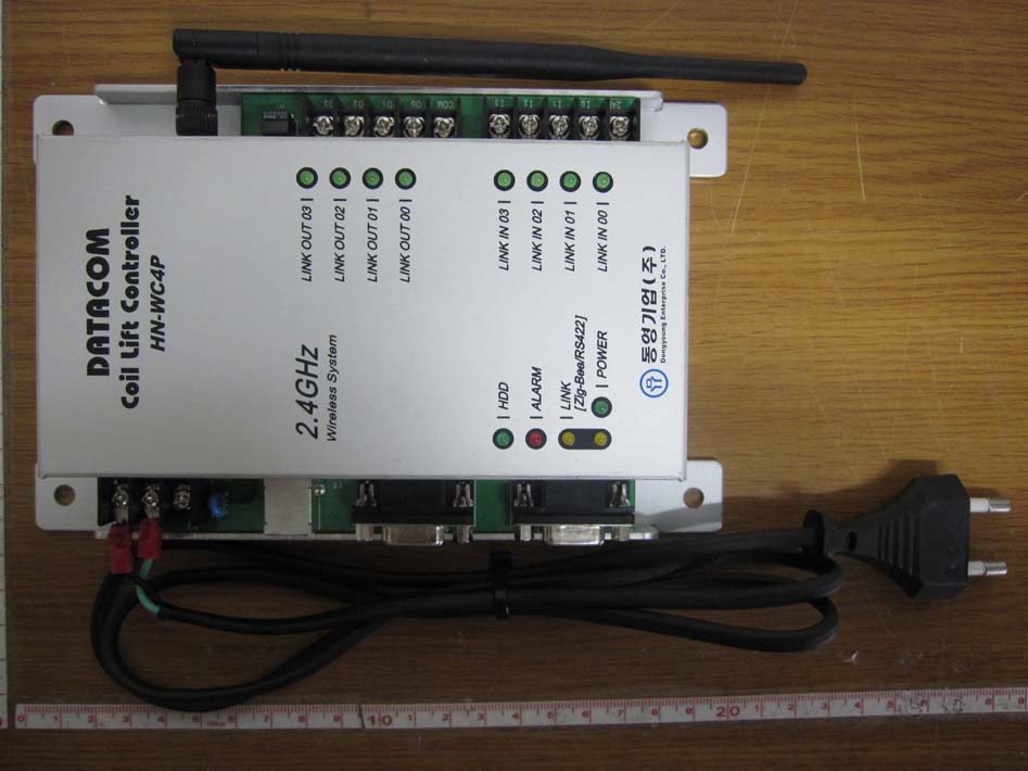
4-PORT COIL LIFT SYSTEM - FCC ID YN9-HN-WC4P - DONGYOUNG Enterprise Co., Ltd.
YN9-HN-WC4P

4-PORT COIL LIFT SYSTEM

Aug 19, 2010

Equipment Class

DTS - Digital Transmission System