YNG-BN01L02Wristband
Dongguan Yuanfeng Technology Co., Ltd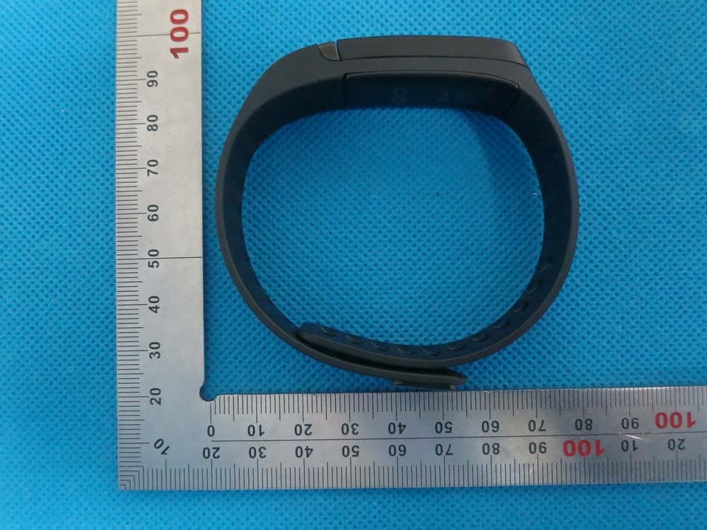
Click to zoom
Application Details
- Equipment Class
- DTS - Digital Transmission System
- Date of Grant
- Jan 11, 2015
- Application Purpose
- Original Equipment
- Date of Application
- Jan 11, 2015
- Equipment Note
- Wristband
- Frequency Range
- 2402.00000000 - 2480.00000000
- Country
- China
Documents & Files
Document Text
Text extracted from the exhibit documents filed with the FCC. Open a document above to read the original.
Users Manual
Quick Start Guide Wristband Model name:BN01L02 FCC ID: YNG‐BN01L02 Includes: 1. BN01L02 (Touch device) 2. User Manual Instructions: 1. The device can be charging by PC USB port 2. Allow Touch device to charge for at least 90 minutes. Paring: 1.Ensure the device is turned off. 2.Turn on,blue led flashing after solid blue keeps for 4 seconds,this will indicate your device is now in pairing mode. 3.Place the device and the Bluetooth device to which you would like to pair it within the operationg distance.we recommend keeping the two devices within 33ft. Product Specification Model: BN01L02 Name: wristband feature: The device work with ios/android APP, track and record user’s activity and sleep. Activity Tracking (Steps, Distance, Calories, Active Minutes, Sedentary) Sleep Tracking (Duration, Wakeup Events, Light Sleep, Deep Sleep) it is also a good partner to a phone, alert the email, sms,calendar,and music. Specification: Hardware Soc NRF51822 SoC with BLE4.0 Display 0.91” OLED 128*32 pixels G-sensor Yes, BT Yes, BT4.0 Vibration Yes Battery rechargeable Li-Polymer battery waterproof IPX7 Connect Wireless: Bluetooth 4.0 for Android/iOS USB Dongle for MAC/PC Support device Android / iOS device, MAC/PC This equipment has been tested and found to comply with the limits for a Class B digital device, pursuant to part 15 of the FCC Rules. These limits are designed to provide reasonable protection against harmful interference in a residential installation. This equipment generates, uses and can radiate radio frequency energy and, if not installed and used in accordance with the instructions, may cause harmful interference to radio communications. However, there is no guarantee that interference will not occur in a particular installation. If this equipment does cause harmful interference to radio or television reception, which can be determined by turning the equipment off and on, the user is encouraged to try to correct the interference by one or more of the following measures: • Reorient or relocate the receiving antenna. • Increase the separation between the equipment and receiver. • Connect the equipment into an outlet on a circuit different from that to which the receiver is connected. • Consult the dealer or an experienced radio/TV technician for help. Modifications not expressly approved by the manufacturer could void the user’s authority to operate the equipment under FCC rules. This device complies with Part 15 of the FCC Rules. Operation is subject to the following two conditions: (1) this device may not cause harmful interference, and (2) this device must accept any interference received, including interference that may cause undesired operation of the device. Changes or modifications to this unit not expressly approved by the party responsible for compliance could void the user's authority to operate the equipment. FCC RF Radiation Exposure Statement: This equipment complies with FCC radiation exposure limits set forth for an uncontrolled environment. End users must follow the specific operating instructions for satisfying RF exposure compliance. This device must not be co‐located or operated in conjunction with any other antenna or transmitter instructions for satisfying RF exposure compliance. NOTE: Operating temperature ranges from ‐4°F to 149°F (‐20°C to 65°C). Relative humidity ranges from 0% to 93% RH. Compliant with the standard R&TTE 99/CE/05 Limited Hardware Warranty Last updated 8/06/2013. For future updates, go to www.YF.com/legal 1. Limited Warranty. YF warrants to the end user customer (“Customer”) of the electronic device (“Product”) that the Product hardware components (“Product Hardware”), when used in accordance with the documentation furnished by YF (“Documentation”), will be free in all material respects of defects in materials and workmanship (“Limited Warranty”), for a period of one (1) year after the date of purchase by Customer of the applicable Product from YF or YF authorized reseller (the “Warranty Period”). If the Product Hardware (or any component or portion thereof) fails to conform to the Limited Warranty, YF, at its own expense and as its sole obligation, and Customer’s sole and exclusive remedy, for breach of this warranty will either (at YF sole discretion) (a) repair or replace any defective Product Hardware; or (b) accept the return of the Product incorporating the defective Product Hardware and refund to Customer the fees actually paid by Customer to YF or YF authorized reseller for such Product. Replacement Products and Product Hardware may be refurbished and/or different models will be supplied, but will be functionally equivalent to the Products or Product Hardware being replaced. When a Product or Product Hardware is replaced, any replacement item becomes Customer’s property and the replaced Product or Product Hardware becomes YF property. Any Product that has either been repaired or replaced under this Limited Warranty will have warranty coverage for the longer of ninety (90) days or the remaining Warranty Period. This Limited Warranty is transferable from Customer to subsequent Product owners, but the Warranty Period will not be extended for any such transfer. 2. Process. YF warranty obligations are conditioned on Customer (a) notifying YF using the customer care contact information available at YF website (www.YFTECHNOLOGY.com/customercare), during the Warranty Period, of any failure of The Product to meet the Limited Warranty, including a detailed description of such alleged failure and proof of purchase information as requested by YF, (b) otherwise complying with YF then‐current return merchandise authorization guidelines (if any), and (c) shipping the affected Product, at Customer’s cost, to YF or YF designated third party facility for repair or replacement. Before Customer ships Customer’s Product to YF for warranty service. Customer is responsible for making a separate backup copy of the contents of the Product. THE CONTENTS OF THE PRODUC…
Text truncated - open the document above for the full version.
Cover Letter(s)
Jan.04, 2015 Federal Communication Commission Authorization and Evaluation Division FCC ID: YNG-BN01L02 Re: Confidentiality Request Pursuant to Sections 0.457 and 0.459 of the Commission’s Rules, the applicant hereby requests confidential treatment of information applied this application as outlined below: 1: Block Diagram 2: Circuit Diagram 3: Parts List 4.Operational Description The above materials contain trade secrets and proprietary information not customarily released to the public. The public disclosure of these matters might be harmful to the applicant and provide unjustified benefits to its competitors. The Applicant understands that pursuant to Rules 0.457, disclosure of this Application and all accompanying documentation will not be made before the date of the Grant for this application. Sincerely, Dongguan Yuanfeng Technology Co., Ltd Contact person: Polly Qiu Title: QA Supervisor
External Photos
External Photos TOP VIEW OF EUT BOTTOM VIEW OF EUT FRONT VIEW OF EUT BACK VIEW OF EUT LEFT VIEW OF EUT RIGHT VIEW OF EUT VIEW PO W OF EUT (P ORT OF EUT PORT) T -2
ID Label/Location Info
FCC ID Label Location FCC ID: YNG-BN01L02
Internal Photos
Internal Photos OPEN VIEW OF EUT-1 OPEN VIEW OF EUT-2 INTERNAL VIEW OF EUT-1 Antenna INTERNAL VIEW OF EUT-2 INTERNAL VIEW OF EUT-3
Test Report
Page 1 of 51 FCC Test Report Report No.: AGC01705141203FE08 FCC ID : YNG‐BN01L02 APPLICATION PURPOSE : Original Equipment PRODUCT DESIGNATION : Wristband BRAND NAME : N/A MODEL NAME : See page 5 CLIENT : Dongguan Yuanfeng Technology Co., Ltd. DATE OF ISSUE : Dec.19,2014 STANDARD(S) : FCC Part 15 Rules REPORT VERSION : V1.0 Attestation of Global Compliance (Shenzhen) Co., Ltd CAUTION: This report shall not be reproduced except in full without the written permission of the test laboratory and shall not be quoted out of context. Report No.: AGC01705141203FE08 Page 2 of 51 Report Revise Record Report Version Revise Time Issued Date Valid VersionNotes V1.0 / Dec.19,2014 Valid Original Report Report No.: AGC01705141203FE08 Page 3 of 51 TABLE OF CONTENTS 1. VERIFICATION OF COMPLIANCE......................................................................................................... 5 2.GENERAL INFORMATION ...................................................................................................................... 6 2.1PRODUCT DESCRIPTION ............................................................................................................... 6 2.2 RELATED SUBMITTAL(S)/GRANT(S) ............................................................................................. 6 2.3TEST METHODOLOGY .................................................................................................................... 6 2.4 TEST FACILITY ................................................................................................................................ 6 2.5 SPECIAL ACCESSORIES ................................................................................................................ 7 2.6 EQUIPMENT MODIFICATIONS ....................................................................................................... 7 2.7 MEASUREMENT UNCERTAINTY ................................................................................................... 7 3. SYSTEM TEST CONFIGURATION ......................................................................................................... 8 3.1 CONFIGURATION OF TESTED SYSTEM ....................................................................................... 8 3.2 EQUIPMENT USED IN TESTED SYSTEM ...................................................................................... 8 3.3. SUMMARY OF TEST RESULTS ..................................................................................................... 8 4. DESCRIPTION OF TEST MODES .......................................................................................................... 9 5. ANTENNA REQUIREMENT .................................................................................................................... 9 5.1. STANDARD APPLICABLE .............................................................................................................. 9 5.2. TEST RESULT ................................................................................................................................ 9 6. TEST FACILITY ..................................................................................................................................... 10 7. RADIATED EMISSION .......................................................................................................................... 11 7.1 MEASUREMENT PROCEDURE .................................................................................................... 11 7.2 TEST SETUP .................................................................................................................................. 12 7.3 LIMITS AND MEASUREMENT RESULT ........................................................................................ 13 7.4 TEST RESULT (WORST MODULATION: GFSK) ................................................................................ 13 8. BAND EDGE EMISSION ....................................................................................................................... 26 8.1. MEASUREMENT PROCEDURE ................................................................................................... 26 8.2. TEST SET-UP ............................................................................................................................... 26 8.3. TEST RESULT .............................................................................................................................. 27 9. 6DB BANDWIDTH ................................................................................................................................ 31 9.1. TEST PROCEDURE ...................................................................................................................... 31 9.2. SUMMARY OF TEST RESULTS/PLOTS ...................................................................................... 31 10. CONDUCTED OUTPUT POWER ....................................................................................................... 33 10.1. MEASUREMENT PROCEDURE ................................................................................................. 33 10.2. TEST SET-UP (BLOCK DIAGRAM OF CONFIGURATION) ........................................................ 33 10.3. LIMITS AND MEASUREMENT RESULT ..................................................................................... 34 11. MAXIMUM CONDUCTED OUTPUT POWER SPECTRAL DENSITY ................................................ 36 11.1 MEASUREMENT PROCEDURE .................................................................................................. 36 Report No.: AGC01705141203FE08 Page 4 of 51 11.2 TEST SET-UP (BLOCK DIAGRAM OF CONFIGURATION) ......................................................... 36 11.3 LIMITS AND MEASUREMENT RESULT ...................................................................................... 36 12. FCC LINE CONDUCTED EMISSION TEST ....................................................…
Text truncated - open the document above for the full version.
Test Setup Photos
APPENDIX IV PHOTOGRAPHS OF TEST SETUP FCC LINE CONDUCTED EMISSION TEST SETUP FCC RADIATED EMISSION TEST SETUP
Contact Information
Applicant
jianwei Chen(Quality Director)
Test Firm
Attestation of Global Compliance Shenzhen Co. Ltd.Forrest Lei
Technical Specifications
| # | Rule Parts | Frequency Range | Power Output |
|---|---|---|---|
| 1 | 15C | 2.40 GHz - 2.48 GHz | 2.00 mW |
Other Applications from Dongguan Yuanfeng Technology Co., Ltd
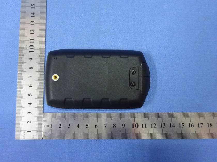
YNGPF22
Nov 24, 2015GPS Portable Navigation Device
Equipment Class
DXX - Part 15 Low Power Communication Device Transmitter
YNGPM22-3502
Jul 14, 2015GPS Portable Navigation Device
Equipment Class
DTS - Digital Transmission System
YNGMP83-8031
Mar 04, 2014Tablet PC
Equipment Class
DTS - Digital Transmission System
YNGAW986-8034
Jan 13, 2014Tablet PC
Equipment Class
DXX - Part 15 Low Power Communication Device Transmitter
YNGMR13-1301
Dec 20, 2012Tablet PC
Equipment Class
DTS - Digital Transmission System