YOA-XP510012.4G Wireless Mouse
Xoopar Limited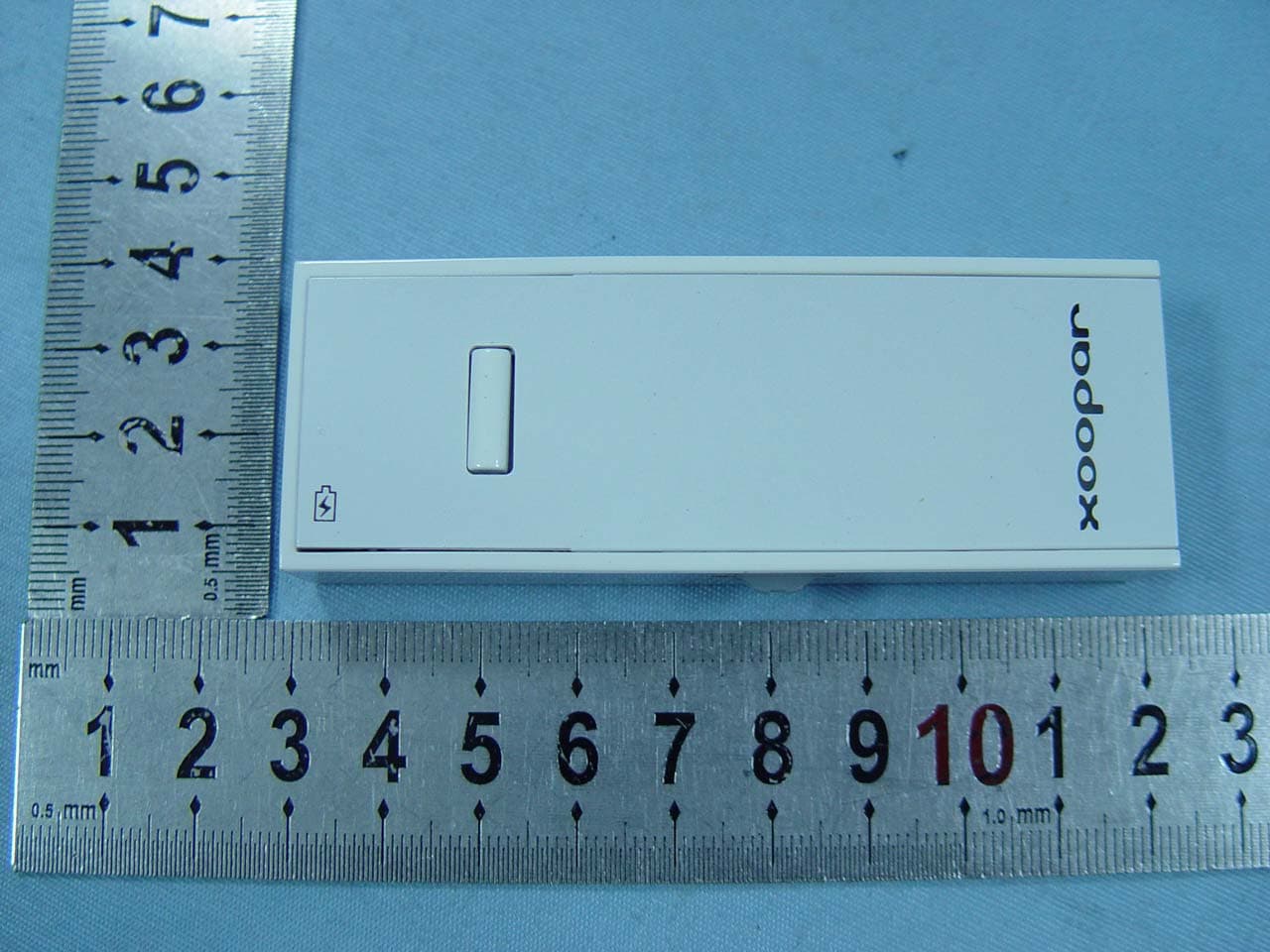
Click to zoom
Application Details
- Equipment Class
- DXX - Part 15 Low Power Communication Device Transmitter
- Date of Grant
- Aug 18, 2010
- Application Purpose
- Original Equipment
- Date of Application
- Aug 18, 2010
- Equipment Note
- 2.4G Wireless Mouse
- Frequency Range
- 2401.00000000 - 2480.00000000
- Company
- Xoopar Limited
- Country
- China
Documents & Files
Document Text
Text extracted from the exhibit documents filed with the FCC. Open a document above to read the original.
Users Manual
2.4G Wireless Mouse User Manual Packaging Icon Super Mini, (=Left button, =Right button, Scroll Wheel) 2.4GHz wireless (interference-free) Nano Receiver (plug and stay ) 1000dpi, Built-In Rechargeable Battery 3-min auto sleep Drawing on Instruction Manual right button, left button, scroll wheel Nano Receiver USB Charging Cable & Icon Indication (Mouse can be used during charging mode) Description on Packaging Backcard / Instruction Manual Super Mini Size 2.4GHz wireless(up to 10M working distance) Nano Receiver (plug and stay ) 1000dpi, Built-In Rechargeable Battery (100 mA, battery life up to one month) 3-min auto sleep Plug and Play, Win & Mac Accessories included: Velvet Pouch, USB Charging Cable FCC STATEMENT 1. This device complies with Part 15 of the FCC Rules. Operation is subject to the following two conditions: (1) This device may not cause harmful interference, and (2) This device must accept any interference received, including interference that may cause undesired operation. 2. Changes or modifications not expressly approved by the party responsible for compliance could void the user’s authority to operate the equipment. NOTE: This equipment has been tested and found to comply with the limits for a Class B digital device, pursuant to Part 15 of the FCC Rules. These limits are designed to provide reasonable protection against harmful interference in a residential installation. This equipment generates, uses and can radiate radio frequency energy and, if not installed and used in accordance with the instructions, may cause harmful interference to radio communications. However, there is no guarantee that interference will not occur in a particular installation. If this equipment does cause harmful interference to radio or television reception, which can be determined by turning the equipment off and on, the user is encouraged to try to correct the interference by one or more of the following measures: -- Reorient or relocate the receiving antenna. -- Increase the separation between the equipment and receiver. -- Connect the equipment into an outlet on a circuit different from that to which the receiver is connected. -- Consult the dealer or an experienced radio/TV technician for help.
Block Diagram
Applicant: Xoopar Limited FCC ID: YOA-XP51001 Block Diagram MCU SN8P2613X LED KEY CODER 3.7V Li-ion 2.7V LDO RFIC Bk2401wd 16MHz Crystal DATA PCB embedded antenna SENS
ID Label/Location Info
FCC Certification label Sample
ID Label/Location Info
FCC Certification Label Location Sample Label location
Internal Photos
Antenna
Operational Description
Applicant: Xoopar Limited FCC ID: YOA-XP51001 Operation Description The transmitter is mainly composed of two parts: radio modem and baseband microprocessor. The microcontroller scans keystrokes, wheel and sensor, then packs the data by adding preambles, frame information, and error checking bytes. The radio system uses one of 80 channels (the frequency range is 2.401-2.480GHz) to send signal in random, when the data validation error change frequency. The transmitter is powered by 3.7V Li-ion battery. The power consumption of RF module is about 2.7mA, the total power consumption about 11mA in normal working mode. It will enter sleep mode if no key be pressed or no motion after 30 second, in this mode the total power consumption only about 100-200uA. The transmitter will send sync packets after being powered on, and then search Dongle's responses. This is search mode. If any responses-packets be received, the transmitter will enter normal working mode. Then, if the transmitter loses synchronization, it will enter sleep mode. Antenna is formed by a copper trace on the PCB. Common grounding on PCB is not connected to real external ground. Power supply is DC 3.7V by Li-ion battery.
Schematics
5 5 4 4 3 3 2 2 1 1 DD CC BB AA REGOA RSSI R E G O A REGOA VDD D RF SDIO RF SCK RF SCS MOTSWK SDIO KR RF SCS RF SCK RF GIO1 A B B A RSSI BATT+ KLKR 2V7 KL 2V7 SCLK 2V7 B RF GIO1 A SCLK SDIO MOTSWK RF SDIO BATT+BATT_IN BATT+ BATT_IN 2V7 2V7 Title SizeDocument NumberRev Date:Sheetof <Doc><RevCode> MS-PCB NV-VER1.0.DSN B 11Monday, November 23, 2009 Title SizeDocument NumberRev Date:Sheetof <Doc><RevCode> MS-PCB NV-VER1.0.DSN B 11Monday, November 23, 2009 Title SizeDocument NumberRev Date:Sheetof <Doc><RevCode> MS-PCB NV-VER1.0.DSN B 11Monday, November 23, 2009 R1133ER1133E C12103C12103TP5TP5 1 D2LED3D2LED3 12 C15560PC15560P R3330ER3330E R61K65R61K65 C16104C16104 D1LED3D1LED3 12 C9 1P C9 1P C6 2.2UF C6 2.2UF R8330ER8330E C 2 2 . 2 U F C 2 2 . 2 U F K3 KW-1204 K3 KW-1204 123 Y1 16MHz XTAL Y1 16MHz XTAL EC747U/16VEC747U/16V CN4 CON2-1.5 CN4 CON2-1.5 1 2 C522PFC522PF R5330R5330 C 4 1 . 5 N F C 4 1 . 5 N F K1 KW-1204 K1 KW-1204 1 2 3 L23.1NHL23.1NH R2 10E R2 10E C11 10P C11 10P U2 SN8P2613X SSOP20 U2 SN8P2613X SSOP20 P0.1/INT1 1 P1.2 2 P1.3 3 P0.0/INT0 4 P1.5/RST/VPP 5 GND 6 P5.0 7 P5.1 8 P5.2 9 P5.3 10 P5.4/BZ0/PWM0 11 P5.5 12 P5.6 13 P5.7 14 VDD 15 XO/P1.4 16 XI/P1.6 17 P1.0 18 P1.1 19 P1.7 20 CN2 CON3-2.0 CN2 CON3-2.0 1 2 3 C17 100P C17 100P R162MR162M C10 1P C10 1P C 1 4 0 . 1 U F C 1 4 0 . 1 U F C220.1UFC220.1UF R4200R4200C1910nfC1910nf C 2 4 1 0 4 C 2 4 1 0 4 K2 KW-1204 K2 KW-1204 1 2 3 C7 10PF C7 10PF L 1 N C L 1 N C Q1 S9015 Q1 S9015 1 2 3 R734K8 1%R734K8 1% C 1 2 . 2 U F C 1 2 . 2 U F U1 A7105 U1 A7105 RSSI 1 BPBG 2 RFI 3 RFO 4 VDA2 5 V T 6 G N D 7 X I 8 X O 9 V D A 3 1 0 SCS 11 SCK 12 DVDD 13 SDIO 14 GND 15 G I O 1 1 6 V D A 1 2 0 R E G 1 1 9 C K O 1 8 G I O 2 1 7 coder1 CON3-2.0 coder1 CON3-2.0 1 2 3 U6 AS3020 U6 AS3020 CHRG 1 GND 2 BAT 3 VCC 4 PROG 5 C 2 1 3 3 P F C 2 1 3 3 P F R110KR110K U4 PAN3204 U4 PAN3204 OSC_RES 1 MOTSWK 2 SDIO 3 SCLK 4 LED 5 VSS 6 VDD 7 VDDA 8 U5 SE5509B-2.5V U5 SE5509B-2.5V VIN/1 1 GND/2 2 EN/3 3 DP/4 4 VOUT/5 5 L 3 1 . 2 N H L 3 1 . 2 N H C 1 8 0 . 1 U F C 1 8 0 . 1 U F C 2 6 1 0 3 C 2 6 1 0 3 D3LED3D3LED3 12 C8 NC C8 NC C13103C13103 C 2 0 3 3 P F C 2 0 3 3 P F D4LED3D4LED3 12 C 3 1 2 0 P C 3 1 2 0 P C25 105 C25 105 C231UFC231UF E C 6 4 7 U / 1 6 V E C 6 4 7 U / 1 6 V R151MR151M PDF created with FinePrint pdfFactory trial version http://www.fineprint.com
Test Report
Page 1 of 46 FCC ID: YOA-XP51001 ACCURATE TECHNOLOGY CO. LTD REPORT NO. ATE20101674 FCC CERTIFICATION On Behalf of Xoopar Limited 2.4G Wireless Mouse Model No.: XP51001 FCC ID: YOA-XP51001 Prepared for : Xoopar Limited Address : Room 1608-1609, Jin Wei Building 4051 Jiabin Road Luohu Area, Shenzhen, China Prepared by : ACCURATE TECHNOLOGY CO. LTD Address : F1, Bldg. A, Changyuan New Material Port, Keyuan Rd. Science & Industry Park, Nanshan, Shenzhen, Guangdong P.R. China Tel: (0755) 26503290 Fax: (0755) 26503396 Report Number : ATE20101674 Date of Test : August 10-11, 2010 Date of Report : August 12, 2010 Page 2 of 46 FCC ID: YOA-XP51001 ACCURATE TECHNOLOGY CO. LTD REPORT NO. ATE20101674 TABLE OF CONTENTS Description Page Test Report Certification 1. GENERAL INFORMATION .......................................................................................................... 4 1.1. Description of Device (EUT)....................................................................................................................4 1.2. Description of Test Facility ......................................................................................................................4 1.3. Measurement Uncertainty.........................................................................................................................5 2. MEASURING DEVICE AND TEST EQUIPMENT ..................................................................... 6 3. SUMMARY OF TEST RESULTS................................................................................................... 7 4. FUNDAMENTAL AND HARMONICS RADIATED EMISSION FOR SECTION 15.249(A) 8 4.1. Block Diagram of Test Setup....................................................................................................................8 4.2. The Emission Limit ..................................................................................................................................9 4.3. Configuration of EUT on Measurement ...................................................................................................9 4.4. Operating Condition of EUT ....................................................................................................................9 4.5. Test Procedure ........................................................................................................................................10 4.6. The Field Strength of Radiation Emission Measurement Results ..........................................................11 5. SPURIOUS RADIATED EMISSION FOR SECTION 15.249(D) ............................................. 14 5.1. Block Diagram of Test Setup..................................................................................................................14 5.2. The Emission Limit For Section 15.249(d) ............................................................................................15 5.3. EUT Configuration on Measurement .....................................................................................................15 5.4. Operating Condition of EUT ..................................................................................................................15 5.5. Test Procedure ........................................................................................................................................16 5.6. The Emission Measurement Result ........................................................................................................17 6. BAND EDGES ................................................................................................................................. 20 6.1. The Requirement ....................................................................................................................................20 6.2. EUT Configuration on Measurement .....................................................................................................20 6.3. Operating Condition of EUT ..................................................................................................................20 6.4. Test Procedure ........................................................................................................................................20 6.5. The Measurement Result ........................................................................................................................21 7. ANTENNA REQUIREMENT........................................................................................................ 23 7.1. The Requirement ....................................................................................................................................23 7.2. Antenna Construction .............................................................................................................................23 APPENDIX I ( TEST CURVES) (22 pages) Page 3 of 46 FCC ID: YOA-XP51001 ACCURATE TECHNOLOGY CO. LTD REPORT NO. ATE20101674 Test Report Certification Applicant : Xoopar Limited Manufacturer : Xoopar Limited EUT Description : 2.4G Wireless Mouse (A) MODEL NO.: XP51001 (B) SERIAL NO.: N/A (C) POWER SUPPLY: 3.7V DC (Li-ion battery) Measurement Procedure Used: FCC Rules and Regulations Part 15 Subpart C Section 15.249 ANSI C63.4: 2003 The device described above is tested by ACCURATE TECHNOLOGY CO. LTD to determine the maximum emission levels emanating from the device. The maximum emission levels are compared to the FCC Part 15 Subpart C Section15.249 limits. The measurement results are contained in this test report and ACCURATE TECHNOLOGY CO. LTD is assumed full responsibility for the accuracy and completeness of these measurements. Also, this report shows that the Equipment Under Test (EUT) is to be technically compliant with the FCC requirements. This report applies to above tested sample only. This report shall not be reproduced in part without written approval of ACCURATE TECHNOLOGY CO. LTD. Date of Test : August 10-…
Text truncated - open the document above for the full version.
Test Setup Photos
Radiated emissions test < 1GHz Radiated emissions test > 1GHz
Contact Information
Applicant
Derek Tsui(GM)
Test Firm
Accurate Technology Co., Ltd.Sean Liu
Technical Specifications
| # | Rule Parts | Frequency Range | Power Output |
|---|---|---|---|
| 1 | 15C | 2.40 GHz - 2.48 GHz | - |
Other Applications from Xoopar Limited
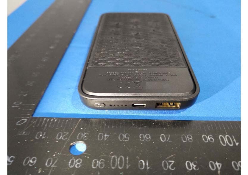
YOAXP61067
Apr 09, 2020BUBBLE BANG WIRELESS Power Bank 5000 mAh
Equipment Class
DCD - Part 15 Low Power Transmitter Below 1705 kHz
YOA-XG21019-20
Nov 10, 2015Bluetooth Speaker
Equipment Class
DXX - Part 15 Low Power Communication Device Transmitter
YOA-HW31004
Aug 01, 2015Tornado 2 Bluetooth Speaker
Equipment Class
DXX - Part 15 Low Power Communication Device Transmitter
YOAXG21013
Mar 09, 2015Dome Bluetooth Speaker
Equipment Class
DSS - Part 15 Spread Spectrum Transmitter
YOAXG31002
Mar 09, 2015Bluetooth Speaker
Equipment Class
DSS - Part 15 Spread Spectrum Transmitter