YONDNW101014-00rDAC Wireless
A & R CAMBRIDGE(T/A ARCAM)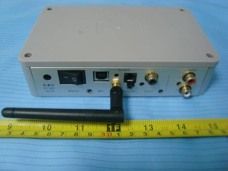
Click to zoom
Application Details
- Equipment Class
- DTS - Digital Transmission System
- Date of Grant
- Nov 04, 2010
- Application Purpose
- Original Equipment
- Date of Application
- Nov 04, 2010
- Equipment Note
- rDAC Wireless
- Frequency Range
- 2403.00000000 - 2473.00000000
- Company
- A & R CAMBRIDGE(T/A ARCAM)
- Country
- United Kingdom
Documents & Files
Document Text
Text extracted from the exhibit documents filed with the FCC. Open a document above to read the original.
Users Manual
1 23425 Connections and Quickstart Guide Guide de démarrage rapide Schnellstartanleitung Snelstartgids 2 3 ... and thank you for purchasing the Arcam rDAC Digital-to-Analogue converter. Arcam has been producing high-quality audio components for over thirty years. During that time we have amassed a wealth of knowledge on both the design and construction of audio components in order to give the best sound performance for the price. This handbook provides guidance for connecting and using your rDAC. We hope that your rDAC will give you years of trouble-free operation. In the unlikely event of any fault, or if you simply require further information about Arcam products, our network of dealers will be happy to help you. Further information can be found on the Arcam website at www.arcam.co.uk. The rDAC development team ... et merci de faire confiance au Arcam rDAC. Arcam produit des composants audio de haute qualité depuis plus de trente ans. Au fil des années, nous avons rassemblé tout un ensemble de connaissances en matière de conception et de construction de composants audio pour vous offrir les meilleures performances acoustiques au meilleur prix. Ce manuel est un guide pour l’utilisation de l’rDAC. Nous espérons que votre système de diffusion musicale Solo vous procurera des années d’écoute musicale sans problème. Si, contre toute probabilité, vous découvriez un défaut ou si vous avez besoin d’informations supplémentaires sur les produits Arcam, notre réseau de revendeurs se fera un plaisir de vous aider. Vous trouverez d’autres informations sur le site Web d’Arcam à l’adresse suivante : www.arcam.co.uk L’équipe de dévelopement rDAC Welcome... Bienvenue... 4 ... Vielen Dank, dass Sie sich für einen Arcam rDAC entschieden haben. Arcam stellt seit beinahe 35 Jahren hochwertige Audiokomponenten her. Während dieser Zeit haben wir viel Wissen und Erfahrung über das Design und den Bau von Audiokomponenten gesammelt, auf deren Grundlage wir Ihnen beste Soundleistung zu einem guten Preis bieten können. Dieses Handbuch bietet eine detaillierte Anleitung zur Bedienung des rDAC. Wir hoffen, dass Ihnen das rDAC viele Jahre lang Freude bereiten wird. Im unwahrscheinlichen Fall eines Produktfehlers oder wenn Sie weitere Informationen zu dem Produkten von Arcam wünschen, wenden Sie sich bitte an einen unserer Händler. Weitere Informationen finden Sie auf der Arcam-Website unter www.arcam.de. Ihr rDAC Development Team ... en hartelijk dank voor uw aankoop van de Arcam rDAC Digitaal naar Analoog omzetter. Arcam produceert al bijna 35 jaar hoogwaardige audiocomponenten. Door de jaren heen hebben we een schat aan kennis opgebouwd over het ontwerp en de constructie van audiocomponenten, zodat we de beste geluidsprestaties voor de prijs kunnen leveren. Deze handleiding is bedoeld om u gedetailleerde informatie over het gebruik van de rDAC geven. Wij hopen dat uw rDAC u jarenlang probleemloos van dienst zal zijn. Mocht het apparaat onverhoopt een fout vertonen, of wilt u gewoon verdere informatie over Arcam-producten, dan staat ons netwerk van dealers klaar om u te helpen. Ga naar de Arcam-website www.arcam.co.uk voor meer informatie. Het rDAC-ontwikkelingsteam Willkommen... Welkom... 5 FCC InFormatIon (For US CUStomerS) 1. ProdUCt This product complies with Part 15 of the FCC Rules. Operation is subject to the following two conditions: (1) This device may not cause harmful interference, and (2) this device must accept any interference received, including interference that may cause undesired operation. 2. ImPortant notICe: do not modIFy thIS ProdUCt This product, when installed as indicated in the instructions contained in this manual, meets FCC requirements. Modification not expressly approved by ARCAM may void your authority, granted by the FCC, to use the product. 3. note This product has been tested and found to comply with the limits for a Class B digital device, persuant to Part 15 of the FCC Rules. These limits are designed to provide reasonable protection against harmful interference in a residential installation. This product generates, uses and can radiate radio frequency energy and, if not installed and used in accordance with the instructions, may cause harmful interference to radio communications. However, there is no guarantee that interference will not occur in a particular installation. If this product does cause harmful interference to radio or television reception, which can be determined by turning the product OFF and ON, the user is encouraged to try to correct the interference by one or more of the following measures: • Reorient or relocate the receiving antenna. • Increase the separation between the equipment and receiver. • Connect the product into an outlet on a circuit different from that to which the receiver is connected. • Consult the local retailer authorized to distribute this type of product or an experienced radio/TV technician for help. 6 Click! 1 2 3 EU UK US Power Adaptor Setup Installation d’Alimentation Electrique Netzteil-Setup Voedingsadapter setup 7 Rear Panel Panneau Arrière Rückseite Achterpaneel OPTICALCOAXUSBANT. R L POWER6V DC 600 mA OUTPUTINPUTS 1 0 Audio Output Sortie analogique Analoge Ausgänge Analoge uitgangen Wireless antenna connection Branchement d’une antenne Anschluss einer Antenne Antenne aansluiting Power connector Prise d’alimentation Netzbuchse Stroomingang Coaxial digital input Connecteur audio numérique électrique Koaxialer Digitaleingang Elektrische digitale audioconnector Optical digital input Connecteur audio numérique optique Optischer Digitaleingang Optische digitale audioconnector USB input Connecteur USB USB-Anschluss USB aansluiting Power Switch Interrupteur secteur Netzschalter Netschakelaar 8 Connections Connexions Anschlüsse Aansluitingen Amplifier Amplificateur Verstärker Versterker DVD / TV CD Player Lecteur de Disque Compact Compact Disc-Spieler CD-speler VOLTAGE SELECT AUDIO OUT L R 12 L R AUX IN REMOTE IN 220 - 240V ~50Hz 110 -120V ~…
Text truncated - open the document above for the full version.
Cover Letter(s)
A & R CAMBRIDGE(T/A ARCAM) A & R CAMBRIDGE(T/A ARCAM)
External Photos
EXHIBIT B - EUT EXTERNAL PHOTOGRAPHS EUT – Top View EUT – Bottom View EUT – Side View
ID Label/Location Info
EXHIBIT A - FCC ID LABELING AND LOCATION FCC ID Label FCC ID Label Location Label here The label shown shall be permanently affixed at a conspicuous location on the device and be readily visible to the user at the time purchase (Labeling requirements per 2.925)
Internal Photos
EXHIBIT C - EUT INTERNAL PHOTOGRAPHS EUT – Cover off View 1 EUT – Cover off View 2 EUT – Main Board Top View EUT – Main Board BottomView EUT – LED Board Top View EUT – LED Board BottomView EUT – RF Module View EUT – RF Module Board Top View EUT – RF Module Board Bottom View EUT – Antenna View EUT – Adapter View 1 EUT – Adapter View 2
RF Exposure Info
A & R CAMBRIDGE (T/A ARCAM) FCC ID: YONDNW101014-00 Report No.: RSZ10080205 Page 9 of 36 FCC Part15.247 Test Report FCC §15.247(i) & §2.1091 - MAXIMUM PERMISSIBLE EXPOSURE (MPE) Applicable Standard According to §1.1307(b)(1), systems operating under the provisions of this section shall be operated in a manner that ensures that the public is not exposed to radio frequency energy level in excess of the Commission’s guidelines. According to §1.1310 and §2.1091 RF exposure is calculated. Limits for General Population/Uncontrolled Exposure Limits for General Population/Uncontrolled Exposure Frequency Range (MHz) Electric Field Strength (V/m) Magnetic Field Strength (A/m) Power Density (mW/cm 2 ) Averaging Time (minutes) 0.3-1.34 614 1.63 *(100) 30 1.34-30 824/f 2.19/f *(180/f 2 ) 30 30-300 27.5 0.073 0.2 30 300-1500 / / f/1500 30 1500-100,000 / / 1.0 30 f = frequency in MHz * = Plane-wave equivalent power density Test Data Predication of MPE limit at a given distance Where: S = power density (in appropriate units, e.g. mW/cm2) P = power input to the antenna (in appropriate units, e.g., mW). G = power gain of the antenna in the direction of interest relative to an isotropic radiator, the power gain factor, is normally numeric gain. R = distance to the center of radiation of the antenna (appropriate units, e.g., cm) Maximum peak output power at antenna input terminal: 14.88 (dBm ) Maximum peak output power at antenna input terminal: 30.76 (mW) Prediction distance: >20 (cm) Predication frequency: 2438 (MHz) Antenna Gain (typical): 2.0 (dBi) Antenna Gain (typical): 1.585 (numeric) The worst case is power density at predication frequency at 20 cm: 0.0097 (mW/cm 2 ) MPE limit for general population exposure at prediction frequency: 1 (mW/cm 2 ) Result: The MPE of device at 20 distances complies with FCC limit.
Test Report
Note: This test report is prepared for the customer shown above and for the device described herein. It may not be duplicated or used in part without prior written consent from Bay Area Compliance Laboratories Corp. This report must not be used by the customer to claim product certification, approval, or endorsement by NVLAP*, NIST, or any agency of the Federal Government. * This report may contain data that are not covered by the NVLAP accreditation and are marked with an asterisk “*” (Rev.2) FCC PART 15.247 MEASUREMENT AND TEST REPORT For A & R CAMBRIDGE (T/A ARCAM) Denny Industrial Centre, Pembroke Avenue, Waterbeach, Cambridge., CB25 9QR, England FCC ID: YONDNW101014-00 Report Type: Original Report Product Type: rDAC Wireless (2.4 GHz Transmitter) Test Engineer: Felix Li Report Number: RSZ10080205 Report Date: 2010-10-30 Reviewed By: Merry Zhao EMC Engineer Prepared By: Bay Area Compliance Laboratories Corp. (Shenzhen) 6/F, the 3rd Phase of WanLi Industrial Building, ShiHua Road, FuTian Free Trade Zone Shenzhen, Guangdong, China Tel: +86-755-33320018 Fax: +86-755-33320008 A & R CAMBRIDGE (T/A ARCAM) FCC ID: YONDNW101014-00 Report No.: RSZ10080205 Page 2 of 36 FCC Part15.247 Test Report TABLE OF CONTENTS GENERAL INFORMATION.......................................................................................................................................4 PRODUCT DESCRIPTION FOR EQUIPMENT UNDER TEST (EUT) .....................................................................................4 OBJECTIVE...................................................................................................................................................................4 RELATED SUBMITTAL(S)/GRANT(S).............................................................................................................................4 TEST METHODOLOGY..................................................................................................................................................4 TEST FACILITY.............................................................................................................................................................4 SYSTEM TEST CONFIGURATION ..........................................................................................................................6 DESCRIPTION OF TEST CONFIGURATION......................................................................................................................6 EUT EXERCISE SOFTWARE..........................................................................................................................................6 EQUIPMENT MODIFICATIONS.......................................................................................................................................6 LOCAL SUPPORT EQUIPMENT LIST AND DETAILS........................................................................................................6 EXTERNAL I/O CABLE..................................................................................................................................................6 CONFIGURATION OF TEST SETUP.................................................................................................................................7 BLOCK DIAGRAM OF TEST SETUP................................................................................................................................7 SUMMARY OF TEST RESULTS ...............................................................................................................................8 FCC §15.247(i) & §2.1091 - MAXIMUM PERMISSIBLE EXPOSURE (MPE)..........................................................9 APPLICABLE STANDARD..............................................................................................................................................9 TEST DATA..................................................................................................................................................................9 FCC §15.203 - ANTENNA REQUIREMENT...........................................................................................................10 APPLICABLE STANDARD............................................................................................................................................10 ANTENNA CONNECTOR CONSTRUCTION....................................................................................................................10 FCC §15.207 (a) - CONDUCTED EMISSIONS .......................................................................................................11 APPLICABLE STANDARD............................................................................................................................................11 MEASUREMENT UNCERTAINTY..................................................................................................................................11 EUT SETUP................................................................................................................................................................11 EMI TEST RECEIVER SETUP.......................................................................................................................................12 TEST EQUIPMENT LIST AND DETAILS.........................................................................................................................12 TEST PROCEDURE......................................................................................................................................................12 TEST RESULTS SUMMARY..........................................................................................................................................12 TEST DATA................................................................................................................................................................12 FCC §15.209, §15.205 & §15.247(d) - SPURIOUS EMI…
Text truncated - open the document above for the full version.
Test Setup Photos
EXHIBIT D - TEST SETUP PHOTOGRAPHS AC Line Conducted Emissions - Front View AC Line Conducted Emissions - Side View Below 1 GHz: Radiated Emissions - Front View Below 1 GHz: Radiated Emissions - Rear View Above 1 GHz: Radiated Emissions - Front View Above 1 GHz: Radiated Emissions - Rear View
Contact Information
Applicant
Michael Sheridan(Operations Director)
Test Firm
Bay Area Compliance Laboratory Corp. (Shenzhen)John Chan
Technical Specifications
| # | Rule Parts | Frequency Range | Power Output |
|---|---|---|---|
| 1 | 15C | 2.40 GHz - 2.47 GHz | 30.76 mW |
Other Applications from A & R CAMBRIDGE(T/A ARCAM)
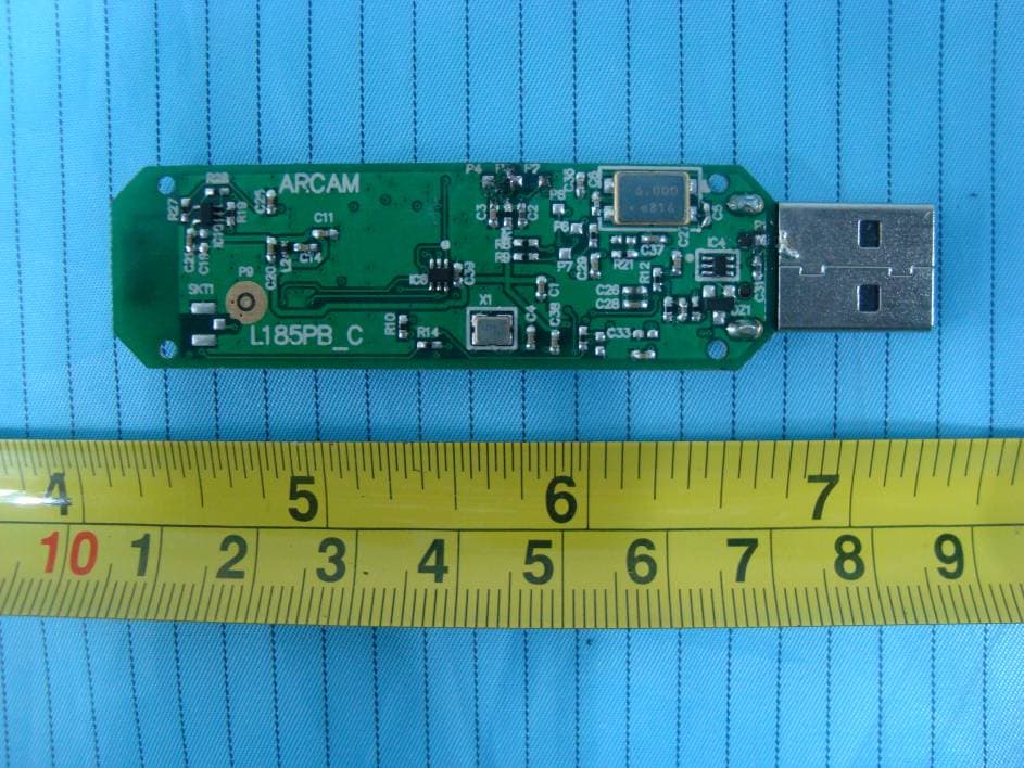
YONDNW101015-00
Nov 17, 2010rWave USB Wireless Audio Transmitter
Equipment Class
DTS - Digital Transmission System