Text extracted from the exhibit documents filed with the FCC. Open a document above to read the original.
Users manual, english The mobile alarm system Kevin, the mobile alarm system V. 1.0 page 2 / 17 Table of contents 1. Introduction --------------- 3 2. Getting started ----------- 4 3. Functionality -------------- 6 3.1 Functionality; general---- 6 3.2 Functionality; ALARM UNIT ------------ 6 3.3 Functionality; HANDSET ------------- 7 4. Alarm modes ------------- 7 4.1 Activation -------------- 7 4.2 Distance Control Mode -------------------- 7 4.3 Travel Mode ---------- 7 4.4 Theft protection ------ 8 4.5 Additional function area monitoring ------- 8 4.6 Stopping an alarm and switching off ----------- 8 4.7 Paging ------------------ 9 5. Settings -------------------- 9 5.1 Settings; alarm modes -- 9 5.2 Settings; activation / deactivation in detail ---- 10 6. Error indication ----------- 11 7. Frequently asked questions (FAQ) --------- 12 Kevin, the mobile alarm system V. 1.0 page 3 / 17 8. Trouble shooting -------- 13 9. Technical data ----------- 14 10. Warnings and Regulations ----------------------------------14 11. Exemption from liability - 15 12. Imprint / Contact ---------- 15 1. Introduction Thank you for purchasing „Kevin“ – your new personal mobile alarm system! With Kevin, you made the right choice. The different modes protect your valuable luggage (e.g. a laptop bag, camera bag, a handbag containing personal valuables) from forgetting (distance control), while travelling (anti purse snatching, as anti-theft mode with disabled vibration sensor) or in anti-theft mode (as anti-theft mode with activated vibration sensor). Kevin, the mobile alarm system V. 1.0 page 4 / 17 2. Getting started Remove the battery insulating strips by pulling at their ends. Kevin is ready for use. In case you need to change your batteries later on: - HANDSET: 2x type GP389 (1.5 V) - ALARM UNIT: 2x type GP357 (1.5 V) Unlocking on the left-hand side Battery compartment, HANDSET HANDSET: slide the cover into the open position and press with a pointed tool (e.g. end of paper clip) onto the unlocking latch on the left- hand side. Once the compartment is open, insert the batteries. Warning: when inserting the batteries, check polarity. Kevin, the mobile alarm system V. 1.0 page 5 / 17 Battery compartment ALARM UNIT ALARM UNIT: open the cover of the battery compartment and insert the batteries (check polarity). Information about the batteries life expectancy: due to an optimized power saving mode, the units have a low power consumption. Thus the batteries last very long (several years can be assumed). Details for storage when not in use for a longer period of time see chapter 5.2, (Section 5.2, settings: activation / deactivation in detail). Bild Batteriefach Alarmgeber Kevin, the mobile alarm system V. 1.0 page 6 / 17 3. Functionality 3.1. Functionality; general Kevin alerts by an acoustic signal (about 105 dbA/10 cm) depending on the operating mode; as soon as the object to be protected is being moved or located outside a defined radius (about 5-10m, depending on the vicinity). The system consists of two units: the ALARM UNIT and the HANDSET. 3.2. Functionality; ALARM UNIT The ALARM UNIT is attached to the object to be monitored using the supplied stainless steel strap. It features a sonorous siren, a distance- and a vibration sensor and a red LED that serves as an optical function control. Due to the high sound pressure, it‘s also possible to tuck the ALARM UNIT away into the object to be monitored (e.g. suitcase). Kevin, the mobile alarm system V. 1.0 page 7 / 17 3.3. Functionality; HANDSET The HANDSET features various carrying options (lanyard, key ring, clip) and serves as a control unit. The different modes can be activated via the 3 buttons, depending on the mode of protection you would like to set. 4. Alarm modes 4.1. Activation To activate: press the button showing the on/off-symbol until you hear the initial beeping signal. Switching power on will be confirmed by the ALARM UNIT via audible signal and via flashing LED-indicator (1x). 4.2. Distance Control Mode By switching on the devices, the distance control mode is activated by default at the same time. This mode is being used to remind the owner from forgetting an object when leaving a certain radius. In case of occurrence, only the sound of the HANDSET will be heard, not the siren of the ALARM UNIT. 4.3 Travel Mode To activate, press button . This mode is being used when the object is to be monitored. This could be the case during a train journey or when the object is carried for instance while Kevin, the mobile alarm system V. 1.0 page 8 / 17 walking (anti purse snatching). If the object is removed from its owner, a sonorous alarm is being triggered on both units. A distance sensor activates the alarm after about 10m. 4.4. Theft protection To activate, press button . Kevin is now in its most sensitive anti-theft protection mode. A built-in vibration sensor detects even the smallest vibrations and triggers the systems alarm. The built-in siren as well as the alarm of the HANDSET will emit the signal. 4.5. Additional function area monitoring In the same mode , Kevin can also be used for area monitoring, provided the alarm unit is placed behind a door or a window. Once the frame of the door / window is being moved, it activates the alarm through the concussion. 4.6. Stopping an alarm and switching off For all modes; the alarm can be switched off by sliding the cover of the handset temporary into the open position. Attention: the alarm remains active in its chosen mode. Switching off: press the button showing the on/off-symbol until you hear the shutdown signal. You will hear an according error signal should you try to turn off the Kevin, the mobile alarm system V. 1.0 page 9 / 17 HANDSET too far away from the ALARM UNIT. 4.7. Paging Within 14 hours after the last use, the HANDSET can be used as a pager to find the ALARM UNIT, should this one has gone lost. This will be done by continuously pressing one of three buttons. After 14h, the system fall…
Text truncated - open the document above for the full version.
CCS Schwe iz AG, Werkstrasse 36, CH-3250 Lyss Federal Communications Commission 7435 Oakland Mills Road Columbia, MD 21046 Lyss, 3. November 2010 Gentlemen: This letter is to comply with Sections 0.457 and 0.459 pertaining to confidential material. CCS Schweiz AG would like the following documents regarding this submission for FCC ID: YPL-KEVIN-BASE to be kept confidential. 1. Schematics 2. BOM 3. Operational Description 4. Block Diagram The above material contains trade secrets or technical data, which would customarily be guarded from competitors. We do not want these documents to be accessible to the general public. Sincerely, Peter Schmitt Head of Business Unit
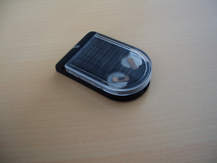
External Photos Base EUT: Base Module Front Cover EUT: Base Module Rear Cover
Document Name KEVIN ID Label and Location Info R04.doc Revision R04 Author SP Engraving on Base: Engraving on TAG: 9 mm 26 mm SmartProtect KEVIN Model No: 20507T FCC ID: YPL-KEVIN-TAG SmartProtect KEVIN Model No: 20507B FCC ID: YPL-KEVIN-BASE 15 mm 10 mm
Internal Photos Base
FCC ID: YPL-KEVIN-BASE Testsite: FCC Registration Number: 96997 The test report shall not be reproduced except in full without the written approval of the testing laboratory. ECL-EMC-TR-10-016-V03.00 Page 1 of 30 Date of issue: 02.09.2010 Signature: Issue-No.: 03 Author: M. Lehmann Head of EMC Date of delivery: 13.01.2010 Checked: T. Vogel Deputy Head of EMC Test dates: 15.01. – 29.01.2010. Pages: 30 EMC-ECL-EMC Test Report No.: 10-016 Equipment under test: Security device (Alarm) for Suitcases and bags called “KEVIN” – Base module FCC ID YPL-KEVIN-BASE Type of test: FCC 47 CFR Part 15 Subpart C Measurement Procedures: ANSI C63.4 (2003) Test result: Passed EMC Test Report No.: 10-016 The test report shall not be reproduced except in full without the written approval of the testing laboratory. ECL-EMC-TR-10-016-V03.00 Page 2 of 30 Manufacturer: CCS Schweiz AG Mr. Schmitt Werkstrasse 36 3250 Lyss Swiss Test Location: TEMPTON Service Plus GmbH European Compliance Laboratory (ECL) Thurn-und-Taxis Strasse 18 D-90411 Nürnberg Tel.: +49 0911 59835 0 Fax: +49 0911 59835 90 General: The purpose of this report is to show compliance to the FCC regulations for unlicensed devices operating under section 15.249 of the Code of Federal Regulations title 47. This report informs about the results of the EMC tests, it only refers to the equipment under test. No part of this report may be reproduced in any form, without written permission. EMC Test Report No.: 10-016 The test report shall not be reproduced except in full without the written approval of the testing laboratory. ECL-EMC-TR-10-016-V03.00 Page 3 of 30 Table of contents 1 TEST RESULTS SUMMERY .................................................................................................................4 2 EQUIPMENT UNDER TEST ..................................................................................................................5 2.1 EUT DESIGNATION............................................................................................................................5 2.2 DESCRIPTION....................................................................................................................................5 2.3 CONFIGURATION...............................................................................................................................5 2.4 TECHNICAL DATA OVERVIEW.............................................................................................................7 3 DESCRIPTION OF THE EMC TEST CENTRE.....................................................................................8 3.1 REGISTRATIONS................................................................................................................................8 3.2 MEASUREMENT UNCERTAINTY...........................................................................................................9 4 ANTENNA REQUIREMENT ................................................................................................................10 4.1 REGULATION...................................................................................................................................10 4.2 RESULT..........................................................................................................................................10 5 RADIATED EMISSIONS TEST ............................................................................................................11 5.1 REGULATION...................................................................................................................................11 5.2 RADIATED EMISSIONS TEST, 30 MHZ TO 26 GHZ.............................................................................12 5.2.1 TEST EQUIPMENT USED: ...........................................................................................................12 5.2.2 TEST PROCEDURES.................................................................................................................12 5.2.3 CALCULATION OF FIELD STRENGTH LIMITS................................................................................15 5.2.4 CALCULATION OF AVERAGE CORRECTION FACTOR....................................................................15 5.2.5 FIELD STRENGTH CALCULATION................................................................................................16 5.3 TEST RESULTS SPURIOUS EMISSION 9 KHZ TO 30 MHZ.....................................................................17 5.4 TEST RESULTS SPURIOUS EMISSION 30 MHZ TO 1 GHZ....................................................................18 5.5 TEST RESULTS SPURIOUS EMISSION 1 GHZ TO 18 GHZ....................................................................20 5.6 TEST RESULTS SPURIOUS EMISSION 18 GHZ TO 26 GHZ..................................................................21 6 FIELD STRENGTH LIMITS (FUNDAMENTAL + HARMONICS) .........................................................22 6.1 REGULATION...................................................................................................................................22 6.2 MAXIMUM FIELD STRENGTH OF THE FUNDAMENTAL...........................................................................23 6.3 BAND EDGE EMISSIONS....................................................................................................................24 7 20 DB BANDWIDTH §15.215 (C) ........................................................................................................25 7.1 RULE..............................................................................................................................................25 7.2 MEASUREMENTS.............................................................................................................................26 8 ACCREDITATION CERTIFICATE .......................................................................................................29 EMC Test Report No.: 10-016 The …
Text truncated - open the document above for the full version.
Test Set-up Photos Base 0,15MHz-30MHz 30MHz-1GHz 1GHz-18GHz 18GHz-26GHz
| # | Rule Parts | Frequency Range | Power Output |
|---|---|---|---|
| 1 | 15C | 2.41 GHz - 2.47 GHz | - |

Mobile Alarm System
Equipment Class
DXX - Part 15 Low Power Communication Device Transmitter
