YPTTELCBGM01Telcheck
Telcare, Inc.
Click to zoom
Application Details
- Equipment Class
- PCB - PCS Licensed Transmitter
- Date of Grant
- Nov 03, 2010
- Application Purpose
- Original Equipment
- Date of Application
- Nov 03, 2010
- Equipment Note
- Telcheck
- Frequency Range
- 1850.20000000 - 1909.80000000
- Company
- Telcare, Inc.
- Country
- United States
Documents & Files
Document Text
Text extracted from the exhibit documents filed with the FCC. Open a document above to read the original.
Users Manual
Telcare Blood Glucose Monitoring System User Manual This meter contains a rechargeable internal battery. In order to save battery power, it will power down (go dark) after 20 seconds. If this happens while you are using the meter, there is nothing wrong. To wake up the meter, either insert a test strip or turn the power button “off” and then “on”. This device will not transmit data when it is not in use. The data transmission time is no more than six minutes. Home glucose monitoring is universally recognized as essential to the management of diabetes and prevention of complications. “ ” Thank you for choosing the Telcare Blood Glucose Meter (BGM) to help you manage your diabetes. The Telcare BGM is an advanced wireless monitoring system that connects you, the patient, with your healthcare provider to enhance your ability to manage your blood glucose levels. The Telcare BGM has been designed to be accurate and easy to use. This manual contains all of the information needed to use and maintain your new blood glucose meter. Please read it carefully before using your new Telcare BGM. Telcare BGM provides an easy and precise way to measure blood glucose using fresh capillary whole blood taken from your fingertip. The added convenience of autocoding can help reduce the chance of inaccurate readings caused by incorrect coding of the meter. The test results are plasma-calibrated for easy comparison to lab results. When your test is complete your results are securely transmitted to the Telserve Web Portal (www.MyTelcare.com), where they may be accessed by you (the patient) and any other authorized person (doctor, educator, family member, etc.), eliminating the need to manually record your results. Telcare BGM is a rechargeable battery operated meter intended for use as an aid by persons with diabetes and by healthcare professionals to monitor glucose concentration in whole blood. If you have questions or simply need more information, please visit our website at www.telcare.com. Thank you again for choosing the Telcare BGM. Table of Contents Your Telcare Blood Glucose Meter The Telcare BGM Device 1 Telcare Test Strips 3 The Display Screen 4 Setting Up Your Telcare BGM 5 Control Solution Modes Performing the Control Test 8 Testing Your Blood Sugars Checklist 14 Preparing Your Lancing Device 16 Understanding Your Results 26 Viewing Your Meter’s Memory 27 Maintenance of Your Telcare BGM Cleaning and Storage 28 Charging the Telcare BGM 29 Troubleshooting 30 Terms of Warranty 33 About Telcare / Contact 34 Your Telcare BGM Unboxing the Telcare BGM for the first time Before we begin, take a moment to go over the contents of your Telcare BGM kit. Your kit should include all of the following items: - Telcare Blood Glucose Meter (battery included) - AC Charger - Lancing Device - Lancets - Instruction Manual Make sure you charge your glucose meter for at least 12 hours before first use. To charge your glucose meter, use the AC Charger included in your kit. You should use the Telcare BGM for: - Testing blood glucose - Testing only with fresh capillary whole blood samples You should NOT use the Telcare BGM for: - The diagnosis of diabetes - Testing blood glucose on newborns - Testing of arterial blood 1 The Telcare BGM Device q w e q w e r Power Button UP / DOWN Keys Enter Button Display Screen 2 t y t y Insert Test Strip (White side up) Charging Port (Do not attempt to insert strip here) r Telcare Test Strips q w Blood Sample End Contact End (Put into device) IMPORTANT NOTES ON TEST STRIPS: • Check the expiration date printed on the test strip bottle and its package. Do not use expired test strips. • Use each test strip immediately after removing it from the bottle. • Do not use wet or damaged test strips. • Keep away from direct sunlight and heat. Store the test strip bottle in a dry, cool place. • Record the “date opened” on the bottle label. Discard the bottle and any remaining test strips 3 months after the date of opening. • Do not operate the meter outside the temperature range of 50 ̊F to 104 ̊F. 3 The Display Screen The Display Screen Wireless Signal Strength Current Time Battery Level Last Test Reading Time of Last Reading q we rt q w e r t 4 From the Display screen, you can see the following things: - Wireless Signal Strength - Current Time - Battery Level - Last Test Reading - Time of Last Reading In this Display screen, use the UP/DOWN buttons (located on the left of your meter) to access the meter’s options: - Test Mode - L1 Control Solution Mode (Low) - L2 Control Solution Mode (High) - Settings Menu Setting Up Your Telcare BGM Your Telcare BGM is preconfigured with your information already stored, including your time zone. During each cellular connection (which occurs after a glucose reading has been saved), the web server will recognize and validate that the time displayed on your Telcare BGM is accurate. The web server will automatically update your Telcare BGM time, if appropriate. Also, if your physical location changes the web server will recognize your time zone change and update your meter’s clock. If you would like to view your meter’s preconfigured settings, navigate to the Settings screen. Getting to the Settings Screen 1. PWR your Telcare BGM Device On 2. Use the UP/DOWN Buttons to reach the “Settings” screen 5 Settings Options Alarms Create up to 3 alarms to help remind yourself when to test next. Date and Time This page allows you to view the Date and Time settings of your device. Volume This page allows you to select the volume of your meter. Use the UP/DOWN keys to select the appropriate volume. There are six possible volumes you may select from. Mobile Network This is an advanced feature. This page allows you to view the details of the mobile network your device uses for communication to the MyTelcare.com Web Portal. Auto-Sync Disabling Auto-sync will prevent the meter from communicating with the MyTelcare.com Web Portal. Readings will still be stored in the Glucose Meter. 6 Ret…
Text truncated - open the document above for the full version.
Cover Letter(s)
3 Bethesda Metro Center – Suite 430 – Bethesda MD, 20814 Date: 2010-09-29 FCC ID: YPTTELCBGM01 To the attention of Federal Communications Commission Authorization and Evaluation Division Confidentiality Request Pursuant to Sections 0.457 and 0.459 of the Commission’s Rules, the Applicant hereby requests confidential treatment of information accompanying this Application as outlined below: The above materials contain trade secrets and proprietary information not customarily released to the public. The public disclosure of these matters might be harmful to the Applicant and provide unjustified benefits to its competitors. The Applicant understands that pursuant to Rule 0.457, disclosure of this Application and all accompanying documentation will not be made before the date of the Grant for this application. Sincerely yours, Name: Jonathan C. Javitt, M.D., CEO Company: Telcare, Inc. Tel.: 240‐396‐6003 E‐mail: [email protected] Operational description, BOM, turn-up procedure, schematics and block Diagram
Cover Letter(s)
3 Bethesda Metro Center – Suite 430 – Bethesda, Maryland 20814 Date: 2010-09-29 AUTHORIZATION LETTER To whom it may concern: We, the undersigned TELECARE, Inc. hereby authorize Bureau Veritas Consumer Products Services (H.K.) Ltd., Taoyuan Branch (BV CPS Taoyuan) of Taiwan to act on our behalf in all matters relating to all processes required in FCC Part 22/24 and any communication needed with the national authority. Any and all acts carried out by BV CPS Taoyuan on our behalf shall have the same effects as acts of our own. If you have any questions regarding the authorization, please don’t hesitate to contact us. Sincerely yours, . Jonathan C. Javitt, M.D., M.P.H. TELECARE Tel.: 240-396-6003 E-mail: [email protected]
External Photos
Page 1 CONSTRUCTION PHOTOS OF EUT Page 2
ID Label/Location Info
( LABEL ) P/N 59106000282 Rev.8/10 T0000001 TELCARE 序號標籤 59106000282 29.4 x 49.4mm ±0.02mm 品名 料號 規格 版次 8/10 五鼎生物技術股份有限公司 Manufactured for: Telcare LLC 3 Bethesda Metro Center, Suite 430, Bethesda, MD 20814 Tel : 240-396-6003 100% 150% FCC ID:YPTTELCBGM01 P/N 59106000282 Rev.8/10 T0000001 Manufactured for: Telcare LLC 3 Bethesda Metro Center, Suite 430, Bethesda, MD 20814 Tel : 240-396-6003 FCC ID:YPTTELCBGM01
Internal Photos
Page 3 Page 4 Page 5 Page 6 Page 7 Page 8
RF Exposure Info
Report No.: SA990908C03 Report Format Version 3.0.1 1 RF EXPOSURE REPORT REPORT NO.: SA990908C03 MODEL NO.: TELCBGM01 FCC ID: YPTTELCBGM01 ACCORDING: FCC Guidelines for Human Exposure IEEE C95.1 APPLICANT: Telcare, Inc. ADDRESS: 3 Bethesda Metro Center Suite 430, Bethesda, Maryland, United States ISSUED BY: Bureau Veritas Consumer Products Services (H.K.) Ltd., Taoyuan Branch LAB ADDRESS: No. 47, 14th Ling, Chia Pau Tsuen, Lin Kou Hsiang, Taipei Hsien 244, Taiwan, R.O.C. TEST LOCATION: No. 19, Hwa Ya 2nd Rd, Wen Hwa Tsuen, Kwei Shan Hsiang, Taoyuan Hsien 333, Taiwan, R.O.C. Report No.: SA990908C03 Report Format Version 3.0.1 2 1. RF EXPOSURE LIMIT LIMITS FOR MAXIMUM PERMISSIBLE EXPOSURE (MPE) FREQUENCY RANGE (MHz) ELECTRIC FIELD STRENGTH (V/m) MAGNETIC FIELD STRENGTH (A/m) POWER DENSITY (mW/cm 2 ) AVERAGE TIME (minutes) LIMITS FOR GENERAL POPULATION / UNCONTROLLED EXPOSURE 300-1500 ... ... F/1500 30 1500-100,000 ... ... 1.0 30 F = Frequency in MHz 2. MPE CALCULATION FORMULA Pd = (Pout*G) / (4*pi*r2) where Pd = power density in mW/cm2 Pout = output power to antenna in mW G = gain of antenna in linear scale Pi = 3.1416 R = distance between observation point and center of the radiator in cm 3. CLASSIFICATION The antenna of this product, under normal use condition, is at least 20cm away from the body of the user. So, this device is classified as Mobile Device. 4. CALCULATION RESULT OF MAXIMUM CONDUCTED POWER FREQUENCY BAND (MHz) MAX CONDUCTED POWER (dBm) ANTENNA GAIN (dBi) DISTANCE (cm) POWER DENSITY (mW/cm 2 ) LIMIT (mW/cm 2 ) 824 ~ 849 32.02 -4 20 0.126 0.558 1850 ~ 1910 29.64 -4 20 0.073 1
RF Exposure Info
香港商立德國際商品試驗有限公司桃園分公司 Bureau Veritas Consumer Products Services (H.K.) Ltd., Taoyuan Branch No SAR justification for FCC ID : YPTTELCBGM01 Maximum number of times per day For serious patient it may examine 6 times blood glucose per day (before and after each meal for serious blood glucose patient and each test is typically 2 hours apart. However, the most of users may use it only 2 to 3 times per week for monitoring glucose level purpose Actual Tx-on time for transmitting The actual Tx-on time for transmitting is less than 0.3 sec (0.15sec for network setup and 0.15 sec for uploading 1KB data to server). As analyzed above, the RF circuit is in passive network receiving mode for most of the time and uses only 0.3 sec maximum total for sending out the RF signal during each test. The meter is design to try 3 times maximum for GPRS/EDGE network connection. Since each GPRS/EDGE network setup will take 8 to 16 sec typically depends on time and location. The loop waiting time for each try is default to 20 sec. If connection to GPRS/EDGE network is not successful after 3 tries, then the meter will set network not available flag and stop trying. In this case the test data will be saved to built-in memory and user can re-try upload at later time. As explain above, the old test data (file size is 1KB which includes Glucose level, test time/date and condition) are saved in memory and user can upload them one by one manually when network is available later if necessary. Meter doesn’t support auto combing or uploading data when new test is in progress. In short, the Tx-on time for the meter is typically 0.3 sec per 2 hours for serious patient 0.3 sec per 48 hours for typical user Duty factor Worst case = 16 seconds plus 0.3 out of 2 x 60 x 60 seconds =16.3 / 7200 =0.0023 香港商立德國際商品試驗有限公司桃園分公司 Bureau Veritas Consumer Products Services (H.K.) Ltd., Taoyuan Branch Source-base time average conducted power table Mode Frequency (MHz) Conducted power (dBm) Conducted power (mW) Source-based time-averaged conducted output power (mW) SAR threshold (mW) GPRS 850 (Time slot 1) 824.2 32.02 1592.21 3.66 72.80 836.6 31.94 1563.15 3.60 71.72 848.8 31.87 1538.15 3.54 70.69 GPRS 850 (Time slot 2) 824.2 32.01 1588.55 3.65 72.80 836.6 31.92 1555.97 3.58 71.72 848.8 31.83 1524.05 3.51 70.69 GRPS1900 (Time slot 1) 1850.2 29.57 905.73 2.08 32.43 1880 29.63 918.33 2.11 31.91 1909.8 29.64 920.45 2.12 31.42 GRPS1900 (Time slot 2) 1850.2 29.54 899.50 2.07 32.43 1880 29.61 914.11 2.10 31.91 1909.8 29.59 909.91 2.09 31.42 EGPRS 850 (Time slot 1) 824.2 26.82 480.84 1.11 72.80 836.6 26.81 479.73 1.10 71.72 848.8 26.95 495.45 1.14 70.69 EGPRS 850 (Time slot 2) 824.2 26.64 461.32 1.06 72.80 836.6 26.61 458.14 1.05 71.72 848.8 27.26 532.11 1.22 70.69 EGRPS1900 (Time slot 1) 1850.2 26.05 402.72 0.93 32.43 1880 25.84 383.71 0.88 31.91 1909.8 25.74 374.97 0.86 31.42 EGRPS1900 (Time slot 2) 1850.2 25.91 389.94 0.90 32.43 1880 25.82 381.94 0.88 31.91 1909.8 25.72 373.25 0.86 31.42 香港商立德國際商品試驗有限公司桃園分公司 Bureau Veritas Consumer Products Services (H.K.) Ltd., Taoyuan Branch Source-base time average EIRP table Mode Frequency (MHz) Conducted power (dBm) EIRP (dBm) EIRP (mW) Source-based time-averaged EIRP (mW) SAR threshold (mW) GPRS 850 (Time slot 1) 824.2 32.02 28.02 633.87 1.46 72.80 836.6 31.94 27.94 622.30 1.43 71.72 848.8 31.87 27.87 612.35 1.41 70.69 GPRS 850 (Time slot 2) 824.2 32.01 28.01 632.41 1.45 72.80 836.6 31.92 27.92 619.44 1.42 71.72 848.8 31.83 27.83 606.74 1.40 70.69 GRPS1900 (Time slot 1) 1850.2 29.57 25.57 360.58 0.83 32.43 1880 29.63 25.63 365.59 0.84 31.91 1909.8 29.64 25.64 366.44 0.84 31.42 GRPS1900 (Time slot 2) 1850.2 29.54 25.54 358.10 0.82 32.43 1880 29.61 25.61 363.92 0.84 31.91 1909.8 29.59 25.59 362.24 0.83 31.42 EGPRS 850 (Time slot 1) 824.2 26.82 22.82 191.43 0.44 72.80 836.6 26.81 22.81 190.99 0.44 71.72 848.8 26.95 22.95 197.24 0.45 70.69 EGPRS 850 (Time slot 2) 824.2 26.64 22.64 183.65 0.42 72.80 836.6 26.61 22.61 182.39 0.42 71.72 848.8 27.26 23.26 211.84 0.49 70.69 EGRPS1900 (Time slot 1) 1850.2 26.05 22.05 160.32 0.37 32.43 1880 25.84 21.84 152.76 0.35 31.91 1909.8 25.74 21.74 149.28 0.34 31.42 EGRPS1900 (Time slot 2) 1850.2 25.91 21.91 155.24 0.36 32.43 1880 25.82 21.82 152.05 0.35 31.91 1909.8 25.72 21.72 148.59 0.34 31.42 Note: Antenna gain of 850 and 1900MHz band is -4dBi Conclusion Since Source-base time average power is below SAR exempt power level, the SAR evaluation is not required.
Test Report
Report No.: RF990908C03 1 Report Format Version 3.0.1 FCC TEST REPORT (PART 22) REPORT NO.: RF990908C03 MODEL NO.: TELCBGM01 FCC ID: YPTTELCBGM01 RECEIVED: Sep. 08, 2010 TESTED: Sep. 14 ~ Sep. 23, 2010 ISSUED: Sep. 29, 2010 APPLICANT: Telcare, Inc. ADDRESS: 3 Bethesda Metro Center Suite 430, Bethesda, Maryland, United States ISSUED BY: Bureau Veritas Consumer Products Services (H.K.) Ltd., Taoyuan Branch LAB ADDRESS: No. 47, 14th Ling, Chia Pau Tsuen, Lin Kou Hsiang, Taipei Hsien 244, Taiwan, R.O.C. TEST LOCATION: No. 19, Hwa Ya 2nd Rd, Wen Hwa Tsuen, Kwei Shan Hsiang, Taoyuan Hsien 333, Taiwan, R.O.C. This test report consists of 48 pages in total. It may be duplicated completely for legal use with the approval of the applicant. It should not be reproduced except in full, without the written approval of our laboratory. The client should not use it to claim product, certification, approval or endorsement by TAF or any government agency. The test results in the report only apply to the tested sample. Report No.: RF990908C03 2 Report Format Version 3.0.1 TABLE OF CONTENTS 1 CERTIFICATION ........................................................................................................4 2 SUMMARY OF TEST RESULTS ................................................................................5 2.1 MEASUREMENT UNCERTAINTY .............................................................................5 3 GENERAL INFORMATION.........................................................................................6 3.1 GENERAL DESCRIPTION OF EUT...........................................................................6 3.2 DESCRIPTION OF TEST MODES.............................................................................7 3.2.1 CONFIGURATION OF SYSTEM UNDER TEST ........................................................7 3.2.2 TEST MODE APPLICABILITY AND TESTED CHANNEL DETAIL.............................8 3.3 GENERAL DESCRIPTION OF APPLIED STANDARDS ..........................................10 3.4 DESCRIPTION OF SUPPORT UNITS .....................................................................10 4 TEST TYPES AND RESULTS .................................................................................. 11 4.1 OUTPUT POWER MEASUREMENT ....................................................................... 11 4.1.1 LIMITS OF OUTPUT POWER MEASUREMENT..................................................... 11 4.1.2 TEST INSTRUMENTS .............................................................................................12 4.1.3 TEST PROCEDURES ..............................................................................................13 4.1.4 TEST SETUP ...........................................................................................................14 4.1.5 EUT OPERATING CONDITIONS .............................................................................14 4.1.6 TEST RESULTS .......................................................................................................15 4.2 FREQUENCY STABILITY MEASUREMENT ...........................................................17 4.2.1 LIMITS OF FREQUENCY STABILIITY MEASUREMENT ........................................17 4.2.2 TEST INSTRUMENTS .............................................................................................17 4.2.3 TEST PROCEDURE ................................................................................................18 4.2.4 TEST SETUP ...........................................................................................................18 4.2.5 TEST RESULTS .......................................................................................................19 4.3 OCCUPIED BANDWIDTH MEASUREMENT...........................................................20 4.3.1 LIMITS OF OCCUPIED BANDWIDTH MEASUREMENT ........................................20 4.3.2 TEST INSTRUMENTS .............................................................................................20 4.3.3 TEST SETUP ...........................................................................................................20 4.3.4 TEST PROCEDURES ..............................................................................................21 4.3.5 EUT OPERATING CONDITION ...............................................................................21 4.3.6 TEST RESULTS .......................................................................................................22 4.4 BAND EDGE MEASUREMENT ...............................................................................24 4.4.1 LIMITS OF BAND EDGE MEASUREMENT.............................................................24 4.4.2 TEST INSTRUMENTS .............................................................................................24 4.4.3 TEST SETUP ...........................................................................................................24 4.4.4 TEST PROCEDURES ..............................................................................................25 4.4.5 EUT OPERATING CONDITION ...............................................................................25 4.4.6 TEST RESULTS .......................................................................................................26 4.5 CONDUCTED SPURIOUS EMISSIONS..................................................................28 4.5.1 LIMITS OF CONDUCTED SPURIOUS EMISSIONS MEASUREMENT ..................28 4.5.2 TEST INSTRUMENTS .............................................................................................28 4.5.3 TEST PROCEDURE ................................................................................................29 4.5.4 TEST SETUP ...........................................................................................................29 4.5.5 EUT OPERATING CONDITIONS .............................................................................29 Report No.: RF990908…
Text truncated - open the document above for the full version.
Test Report
Report No.: RF990908C03-1 1 Report Format Version 3.0.1 FCC TEST REPORT (Part 24) REPORT NO.: RF990908C03-1 MODEL NO.: TELCBGM01 FCC ID: YPTTELCBGM01 RECEIVED: Sep. 08, 2010 TESTED: Sep. 14 ~ Sep. 23, 2010 ISSUED: Sep. 29, 2010 APPLICANT: Telcare, Inc. ADDRESS: 3 Bethesda Metro Center Suite 430, Bethesda, Maryland, United States ISSUED BY: Bureau Veritas Consumer Products Services (H.K.) Ltd., Taoyuan Branch LAB ADDRESS: No. 47, 14th Ling, Chia Pau Tsuen, Lin Kou Hsiang, Taipei Hsien 244, Taiwan, R.O.C. TEST LOCATION: No. 19, Hwa Ya 2nd Rd, Wen Hwa Tsuen, Kwei Shan Hsiang, Taoyuan Hsien 333, Taiwan, R.O.C. This test report consists of 47 pages in total. It may be duplicated completely for legal use with the approval of the applicant. It should not be reproduced except in full, without the written approval of our laboratory. The client should not use it to claim product, certification, approval or endorsement by TAF or any government agency. The test results in the report only apply to the tested sample. Report No.: RF990908C03-1 2 Report Format Version 3.0.1 TABLE OF CONTENTS 1 CERTIFICATION .......................................................................................................4 2 SUMMARY OF TEST RESULTS ...............................................................................5 2.1 MEASUREMENT UNCERTAINTY ............................................................................5 3 GENERAL INFORMATION........................................................................................6 3.1 GENERAL DESCRIPTION OF EUT ..........................................................................6 3.2 DESCRIPTION OF TEST MODES ............................................................................7 3.2.1 CONFIGURATION OF SYSTEM UNDER TEST .......................................................7 3.2.2 TEST MODE APPLICABILITY AND TESTED CHANNEL DETAIL ............................8 3.3 GENERAL DESCRIPTION OF APPLIED STANDARDS .........................................10 3.4 DESCRIPTION OF SUPPORT UNITS ....................................................................10 4 TEST TYPES AND RESULTS ................................................................................. 11 4.1 OUTPUT POWER MEASUREMENT ...................................................................... 11 4.1.1 LIMITS OF OUTPUT POWER MEASUREMENT.................................................... 11 4.1.2 TEST INSTRUMENTS.............................................................................................12 4.1.3 TEST PROCEDURES .............................................................................................13 4.1.4 TEST SETUP...........................................................................................................14 4.1.5 EUT OPERATING CONDITIONS ............................................................................14 4.1.6 TEST RESULTS ......................................................................................................15 4.2 FREQUENCY STABILITY MEASUREMENT...........................................................17 4.2.1 LIMITS OF FREQUENCY STABILIITY MEASUREMENT .......................................17 4.2.2 TEST INSTRUMENTS.............................................................................................17 4.2.3 TEST PROCEDURE................................................................................................18 4.2.4 TEST SETUP...........................................................................................................18 4.2.5 TEST RESULTS ......................................................................................................19 4.3 OCCUPIED BANDWIDTH MEASUREMENT ..........................................................20 4.3.1 LIMITS OF OCCUPIED BANDWIDTH MEASUREMENT .......................................20 4.3.2 TEST INSTRUMENTS.............................................................................................20 4.3.3 TEST SETUP...........................................................................................................20 4.3.4 TEST PROCEDURES .............................................................................................21 4.3.5 EUT OPERATING CONDITION ..............................................................................21 4.3.6 TEST RESULTS ......................................................................................................22 4.4 BAND EDGE MEASUREMENT...............................................................................24 4.4.1 LIMITS OF BAND EDGE MEASUREMENT ............................................................24 4.4.2 TEST INSTRUMENTS.............................................................................................24 4.4.3 TEST SETUP...........................................................................................................24 4.4.4 TEST PROCEDURES .............................................................................................25 4.4.5 EUT OPERATING CONDITION ..............................................................................25 4.4.6 TEST RESULTS ......................................................................................................26 4.5 CONDUCTED SPURIOUS EMISSIONS .................................................................28 4.5.1 LIMITS OF CONDUCTED SPURIOUS EMISSIONS MEASUREMENT .................28 4.5.2 TEST INSTRUMENTS.............................................................................................28 4.5.3 TEST PROCEDURE................................................................................................29 4.5.4 TEST SETUP...........................................................................................................29 4.5.5 EUT OPERATING CONDITIONS ............................................................................29 4.5.6 TEST RESULTS .................................…
Text truncated - open the document above for the full version.
Test Setup Photos
1 PHOTOGRAPHS OF THE TEST CONFIGURATION Test Set up for 15b RADIATED EMISSION TEST 2 Test Set up for Part 22/24 RADIATED EMISSION TEST
Contact Information
Applicant
Edward Medri(V.P. R&D)
Technical Contact
Bureau Veritas CPS (H.K.) Ltd. Taoyuan BranchGary Chang
[email protected]886-3-3183232
No. 19, Hwa Ya 2nd Rd., Kwei Shan Hsiang · Taoyuan Hsien · Taiwan
Non-Technical Contact
Bureau Veritas CPS (H.K.) Ltd. Taoyuan BranchWendy Liao
[email protected]886-3-3183232
Test Firm
Bureau Veritas CPS (H.K.) Ltd. Taoyuan BranchRichard Chen
Technical Specifications
| # | Rule Parts | Frequency Range | Power Output | Emission | Tolerance |
|---|---|---|---|---|---|
| 4 | 24E | 1.85 GHz - 1.91 GHz | 100.00 mW | 242KG7W | 2.5 ppm |
Other Applications from Telcare, Inc.
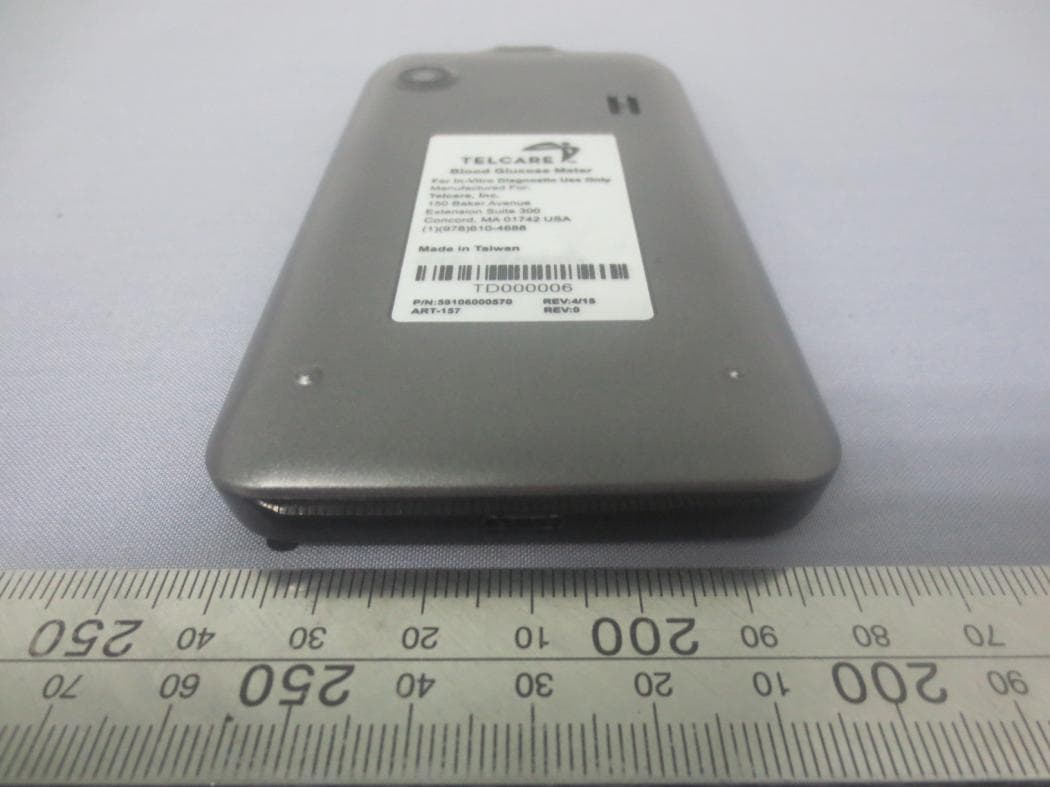
YPTTELCBGM03
Oct 26, 2015Mobile Phone
Equipment Class
DTS - Digital Transmission System