FCCID.CO- FCC ID Database
HomeCompaniesEquipment ClassesSearch

© 2026 FCC ID Database. All rights reserved.

AboutContactData sourced from FCC public records
  1. Home/
  2. Enesco LLC/
  3. YRG4020794RFID

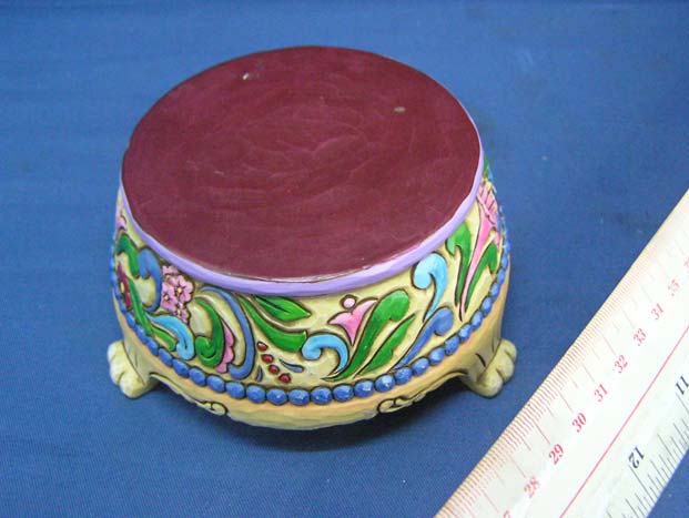
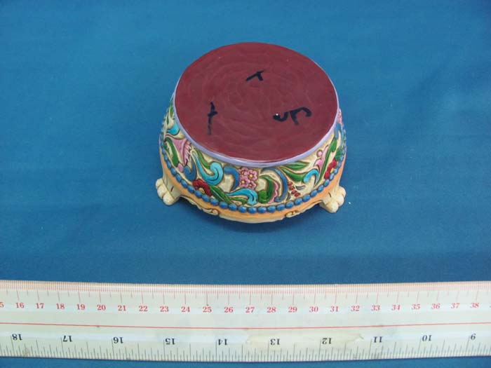
YRG4020794RFIDPrincess Musical Base

Enesco LLC
Princess Musical Base - FCC ID YRG4020794RFID - Enesco LLC
Click to zoom

Application Details

Equipment Class
DXX - Part 15 Low Power Communication Device Transmitter
Date of Grant
Nov 24, 2010
Application Purpose
Original Equipment
Date of Application
Nov 24, 2010
Equipment Note
Princess Musical Base
Frequency Range
13.56000000 - 13.56000000
Company
Enesco LLC
Country
United States

Documents & Files

Select a file to view

Users Manual

↗

Block Diagram

↗

Cover Letter(s)

↗

External Photos

↗

ID Label/Location Info

↗

Internal Photos

↗

Operational Description

↗

Schematics

↗

Test Report

↗
↗

Test Setup Photos

↗

Document Text

Text extracted from the exhibit documents filed with the FCC. Open a document above to read the original.

Users Manual

www.enesco.com 1 Thank you for buying Enesco Product. Please read through this instruction so that you will know how to keep and maintain your product. After you have finished reading the instructions, put it in a safe place for future reference. You have bought the following item. 4020794 Princess Sonata Musical Base (Require AA size battery x 3. Battery not included.) This Musical Base is designed to be used with one of the following figurines at one time. (Figurines are sold separately) 4020788 Ariel Sonata (Sold Separately) 4020789 Aurora Sonata (Sold Separately) 4020790 Belle Sonata (Sold Separately) 4020791 Cinderella Sonata (Sold Separately) 4020792 Jasmine Sonata (Sold Separately) 4020793 Tiana Sonata (Sold Separately) CAUTION • This item contains delicate parts. Please follow the unpack and repack instructions to unpack and repack the item. Recommend to repack the item with the original packing materials. • If you need to move the item, hold the item base to move. Do not hold the item small details such as the legs of the Musical Base. • Only place the item on a stable, solid, flat, level surface, such as a table or shelf. • This item is designed for INDOOR USE only. • This item contains electronic part inside the body. Do not submerge the whole product into water. • Caution‐Not a toy. Decorative Item Only. Do not pass it to children to play with it. Children may break the item parts and pose choking hazards. UNPACK THE ITEM 1. Unpacking the item shall be done on a stable, solid, flat, level surface. 2. Place the Packaged item on the surface. 3. Open the top flip of the gift box. 4. Pull the styrofoam out of the box and place it horizontally on flat surface. 5. Slowly and carefully lift the top piece styrofoam straight up to remove. (During the opening of the styrofoam, if you found that the product is being lifted up by the top piece of styrofoam, carefully close the styrofoam, turn the styrofoam upside down so that the top piece now become the bottom piece. Repeat step 5 to open the upper piece styrofoam.) 6. Slowly and carefully pull the item straight out of the styrofoam by grasping body of the item. (Please make sure the delicate parts will not be broken during the pulling action.) 7. Retain the styrofoam and package box for repack purpose in future. REPACK THE ITEM 1. Before repacking the item, make sure the On/Off switch is being switched to “Off”, and the batteries are removed from the item. (Refer point 1, 2, and 4 of Battery Replacement section for the direction to remove the batteries) 2. Repack shall be done on a stable, solid, flat, level surface. Recommend to repack the item with the original packing materials. 3. When the bottom piece of the styrofoam is sit flat on the surface (with the cavity facing upward), slowly and carefully put the item onto the styrofoam according to the cavity shape. 4. Slowly and carefully put the top piece of the styrofoam on top of the bottom piece of the styrofoam. (Make sure the delicate parts will not be pressed or broken during the repacking process. Check if the two halves of the styrofoam are properly closed) 5. Slowly and carefully put the styrofoam into the gift box. 6. Close the top flip of the gift box. MUSICAL BASE STRUCTURE BATTERY INFORMATION Battery Installation 1. Open the Battery Compartment Cover. 2. Insert 3 pcs AA size batteries into the battery compartment following the battery marking direction with correct polarity. (Suggest using Alkaline Batteries.) 3. Close the Battery Compartment Cover. Battery Replacement When item did not function as intended, it may due to low battery voltage. Please follow the below steps to make battery replacement. 1. Open the Battery Compartment Cover. 2. Remove the old batteries from the battery compartment. 3. Insert 3 pcs AA size batteries into the battery compartment following the battery marking direction with correct polarity. (Suggest using Alkaline Batteries.) 4. Close the Battery Compartment Cover. Caution (Battery usage, handling, disposal) Incorrect use of batteries can result in hazards such as leakage and bursting. Please observe the following: • Risk of explosion if battery is replaced by an incorrect type. • Dispose of used batteries according to the instructions. • Do not mix old and new batteries. • Do not mix alkaline, standard (carbon‐zinc), or rechargeable (nickel‐ cadmium) batteries, or mix batteries with different brands, although they may look similar, different batteries may have different voltages. • Make sure that the plus and minus ends of each battery match the indications in the battery compartment. • Remove batteries from item that isn't going to be used for a month or more. • Do not attempt to destroy or disassemble battery or remove any of its components. • Batteries must be recycled or disposed of properly. Please consult your local waste authority for information regarding available recycling and/or disposal options/instructions. Instruction Manual On/Off Switch Battery Compartment Cover Battery Compartment No screw for this item www.enesco.com 2 • Keep batteries away from children and pets. Do not incinerate ‐ fire and/or serious injury could result from a failure to comply with these warnings. • Do not use or store batteries in direct sunlight or other excessively hot place, such as inside a car or near a heater. This can cause batteries to leak, overheat, explode or catch fire. It can also reduce the life or performance of batteries. OPERATE THE MUSICAL BASE Turn on the Musical Base (Standby Mode) 1. Lift up the Musical Base and turn the Music Base upside down so that the Base can be seen. 2. Install batteries into the item according to Battery Installation section of this instruction manual. 3. Switch the On/Off switch to “On” (A start‐up melody will be heard.) 4. Place the Musical Base on a stable, solid, flat, level surface. • The Musical Base is now being set to “Standby Mode” and ready to be triggered to play Melody of particular Princess Figuri…

Text truncated - open the document above for the full version.

Block Diagram

Block Diagram FCC ID: YRG4020794RFID Crystal Oscillator XTAL2 13.560MHz RFID Reader U2 W55MID50 Antenna MCU U1 W584B150 DC 4.5V 3X AA Batteries Speaker 13.560MHz W55MID50 Data Sheet Winbond Electronics Corp. 5 Revision: A5 Publish Date: 2005/8/19 System Description 2.1 W55MID50 System Block Diagram 2.2 W55MID50 Functional Description Transmission Power Amplifier (PA) It provides 4 different selectable transmission power for Reader chip to support MFID WB Tag's radiation power supply. The external inductor coupling circuit is designed for 13.56MHz magnetic field resonance. The coupled center frequency will depend on equivalent value of external PCB inductor and capacitor. Envelope Detector & Analog Front End The major function of this unit provides MFID WB Tag's data can be extracted. Voltage Regulator The voltage regulator generates the system needs of device power supply. Configuration Register System configuration register controls the all functional settings of W55MID50 such as Tag data Command Extractor Configuration Register Data- Buff. output Data- Buff. I Envelope detector & Analog Front End Oscillation circuit 13.56MHz Voltage Regulator Preamble & Data Clk Generator Decoder (NRZ/ Man.) Reset & Power down Control PA Data- Buff. II TXD

Cover Letter(s)

Letter of Agency I, an officer of Enesco LLC do hereby authorize Intertek Testing Services (Mr. Ben Ho) to act on our behalf in front of the Federal Communications Commission with respect to all matters relating to certification of equipment under Part 15 and Part 18 of the FCC Rules until further notice." I further certify that no party (as defined in §1.2002(b) of CFR 47, 2004) to this application, including myself, is subject to a denial of federal benefits, that includes FCC benefits, pursuant to Section 5301 of the Anti-Drug Abuse Act of 1988, 21 U.S.C.,862. Dated November 10, 2010 By Wing Sze Testing Specialist

External Photos

INTERTEK TESTING SERVICE Report No.: HK10100994-1 FCC ID: YRG4020794RFID Equipment Photographs Model : 4020794 (External)

ID Label/Location Info

Labeling for U.S. + Canada + U.K. + HK markets (Musical Base) Wordings about 1.5 mm height Sticker Label. CE mark will be 5mm height, WEEE logo will be 7 mm Height

Internal Photos

INTERTEK TESTING SERVICE Report No.: HK10100994-1 FCC ID: YRG4020794RFID Equipment Photographs Model : 4020794 (Internal) INTERTEK TESTING SERVICE Report No.: HK10100994-1 FCC ID: YRG4020794RFID Equipment Photographs Model : 4020794 (Internal) INTERTEK TESTING SERVICE Report No.: HK10100994-1 FCC ID: YRG4020794RFID Equipment Photographs Model : 4020794 (Internal) INTERTEK TESTING SERVICE Report No.: HK10100994-1 FCC ID: YRG4020794RFID Equipment Photographs Model : 4020794 (Internal)

Operational Description

FCC ID:YRG4020794RFID Technical Description: The brief circuit description is listed as follows: - U2 W55MID50 acts as RFID Reader IC. - XTAL2 and associated circuit act as 13.560 MHz Oscillator. - SW1 act as On/Off Switch. - U1 W584B150 acts as MCU and Sound Synthesizer. Antenna Used: A loop antenna has been used. W55MID50 Data Sheet Winbond Electronics Corp. 3 Revision: A5 Publish Date: 2005/8/19 General Description Winbond MFID WB (Magnetic Field Identification) series is used in all areas of automatic data capture allowing contactless identification of objects using magnetic field. From ticketing to industrial automation and access control, the applications of MFID are burgeoning. In recent years automatic identification procedures have become very popular in many service industries, purchasing and distribution logistics, industry, manufacturing companies and material flow systems. W55MID50 is one of series in Winbond MFID WB family that supports multi-functional Reader solution and especially focus on toy, security, and consumer related applications. The applications with Winbond MFID WB Tag series such as W55MID10 that provides read-only mask ROM-ID version transponder for mass production solution in toy industrial, meanwhile W55MID15 provides the other solution for manufacture option, which is 243 bonding-ID selection transponder. Besides the single tag transponder application, W55MID35 offers multi-transponder recognition function for intelligent and smart toy applications. W55MID50 provides a wide variety of applications for toy, security, and consumer market meanwhile the W55MID50 is the most cost effective solution on current MFID WB related application market. 1.1 W55MID50 Features ! Magnetic field resonance frequency: 13.56MHz ! Data clock: 22 ~ 66KHz ! Inductive coupled power supplies for transponder's no battery operation ! On-chip rectifier, voltage limiter, clock extraction, power management, uC interface ! Provides NRZ and Manchester coding data format ! Adjustable 4-level of Reader transmission power selection ! Provides serial and parallel mode uC interface ! uC data output rate ≥ 1Mbps ! Low power, low voltage operation ! Supports power-down mode ≤ 1uA ! Operating distance: 0 ~ 10cm ! Operating voltage: 2.4V ~ 5.5V ! Operating temperature: 0 ~ 70 ° C ! Package: Dice form, PDIP-20, SOP-20 ! Reference design PC board Size: 2.0x2.0cm 2 (without PCB antenna) ! Winbond patented "Automatic Reader Transmission Power Adjustment" for Reader optimum transmission power adjust ! Minimize external components W55MID50 Data Sheet Winbond Electronics Corp. 4 Revision: A5 Publish Date: 2005/8/19 1.2 W55MID50 Pin Description Symbol PAD No. I/O Functional Description D3 1 O Data output #3 D2 2 O Data output #2 D1 3 O Data output #1 D0 4 O Data output #0 XIN 5 I Connect to external 13.56MHz oscillator XOUT 6 O Connect to external 13.56MHz oscillator VSS 7 GND Digital power return path CMD 8 I/O R/W configuration register CLK 9 I Command R-W/ Read data clock VDD 10 Power Power path RX_VDD 11 Power Power path of Rx RX_VSS 12 GND Power return path of Rx ENV 13 I Envelope detector input RESET 14 I Reset, low active. TagIn 15 O Indication of tag arrival COIL 16 O PA output to connect with PCB antenna TX_VSS 17 GND Power return path of PA TX_VDD 18 Power Power path of PA W55MID50 Data Sheet Winbond Electronics Corp. 5 Revision: A5 Publish Date: 2005/8/19 System Description 2.1 W55MID50 System Block Diagram 2.2 W55MID50 Functional Description Transmission Power Amplifier (PA) It provides 4 different selectable transmission power for Reader chip to support MFID WB Tag's radiation power supply. The external inductor coupling circuit is designed for 13.56MHz magnetic field resonance. The coupled center frequency will depend on equivalent value of external PCB inductor and capacitor. Envelope Detector & Analog Front End The major function of this unit provides MFID WB Tag's data can be extracted. Voltage Regulator The voltage regulator generates the system needs of device power supply. Configuration Register System configuration register controls the all functional settings of W55MID50 such as Tag data Command Extractor Configuration Register Data- Buff. output Data- Buff. I Envelope detector & Analog Front End Oscillation circuit 13.56MHz Voltage Regulator Preamble & Data Clk Generator Decoder (NRZ/ Man.) Reset & Power down Control PA Data- Buff. II TXD W55MID50 Data Sheet Winbond Electronics Corp. 6 Revision: A5 Publish Date: 2005/8/19 format, Tag detection cycle, output data format, and PA transmission power selection. Reset and Power-down Control The function of system power-down control mode is normally used for power consumption saving. Crystal Oscillation The 13.56MHz system clock generator generates the need of device system clock. Decoder NRZ/Manchester This unit is in charge of Tag data format decoder, which can provide Tag-ID data format decoding of NRZ or Manchester. Data Buffer and Output This unit buffers the Tag-ID data, which is under de-frame processing. W55MID50 Data Sheet Winbond Electronics Corp. 7 Revision: A5 Publish Date: 2005/8/19 Electronic Characteristics 3.1 W55MID50 Absolute Maximum Ratings ParameterRatingUnit Maximum Current in COIL 10 mA Power Dissipation (T a = 70°C) 100 mW Ambient Operating Temperature 0 to +70 ° C Storage Temperature -40 to +85 °C Note: Exposure to conditions beyond those listed under Absolute Maximum Ratings may adversely affect the life and reliability of the device. 3.2 W55MID50 DC Characteristics (VDD-VSS = 4.5 V, Ta = 25 ° C; unless otherwise specified) Parameter Sym. Conditions Min. Typ. Max. Unit Operating Magnetic Field f OP Field in resonation - 13.56 - MHz Operating Voltage V DD Field in resonation 3 - 5.5 V Operating Temperature Tamb Ambient operating temp 0 25 70 ° C Operating Current I OP f OP = 13.56MHz - 22 - mA Stand-by Current I SB Power Down mode enter - 0.7 1 uA Sink Current I SK VoL = 0.3VDD - 10 - mA Source Current I SR VoH = 0…

Text truncated - open the document above for the full version.

Test Report

INTERTEK TESTING SERVICES Report No.: HK10100994-1 Sample No.: 1/3 Code: FCC15C_d / Effective Date: 26 Jan 2010 ( of ) Bandedge Plot – Pursuant to FCC Part 15 Section 15. 225/RSS-210 A2.6 Requirement INTERTEK TESTING SERVICES Report No.: HK10100994-1 Sample No.: 1/3 Code: FCC15C_d / Effective Date: 26 Jan 2010 ( of ) Bandedge Plot – Pursuant to FCC Part 15 Section 15. 225/RSS-210 A2.6 Requirement

Test Report

- The test report only allows to be revised within the retention period unless further standard or the requirement was noticed. - This report is for the exclusive use of Intertek's Client and is provided pursuant to the agreement between Intertek and its Client. Intertek's responsibility and liability are limited to the terms and conditions of the agreement. Intertek assumes no liability to any party, other than to the Client in accordance with the agreement, for any loss, expense or damage occasioned by the use of this report. Only the Client is authorized to permit copying or distribution of this report and then only in its entirety. Any use of the Intertek name or one of its marks for the sale or advertisement of the tested material, product or service must first be approved in writing by Intertek. The observations and test results in this report are relevant only to the sample tested. This report by itself does not imply that the material, product, or service is or has ever been under an Intertek certification program. Intertek Testing Services Hong Kong Ltd. 2/F., Garment Centre, 576 Castle Peak Road, Kowloon, Hong Kong. Tel: (852) 2173 8888 Fax: (852) 2785 5487 Website: www.hk.intertek-etlsemko.com TEST REPORT Report No.: HK10100994-1 Enesco LLC Application For Certification (Original Grant) (FCC ID: YRG4020794RFID) Transmitter Prepared and Checked by: Approved by: Signed On File Kenneth Wong Engineer Chan Chi Hung, Terry Senior Lead Engineer Date: November 12, 2010 INTERTEK TESTING SERVICES Report No.: HK10100994-1 FCC ID: YRG4020794RFID i GENERAL INFORMATION Enesco LLC BRAND NAME: Disney Traditions, MODEL: 4020794 FCC ID: YRG4020794RFID Grantee: Enesco LLC Grantee Address: 225 Windsor Drive, Itasca, IL 60143, USA. Contact Person: Wing Sze Tel: 852-2268 8134 Fax: 852-27300171 e-mail: [email protected] Manufacturer: Yi Xing Sheng Crafts Factory Manufacturer Address: Wei Bu Industrial Park, Qiu Chang Town, Hui Yang District, Huizhou City, Guangdong, China. Brand Name: Disney Traditions Model: 4020794 Type of EUT: Transmitter Description of EUT: Princess Musical Base Serial Number: N/A FCC ID: YRG4020794RFID Date of Sample Submitted: October 29, 2010 Date of Test: November 08, 2010 Report No.: HK10100994-1 Report Date: November 12, 2010 Environmental Conditions: Temperature: +10 to 40°C Humidity: 10 to 90% INTERTEK TESTING SERVICES Report No.: HK10100994-1 FCC ID: YRG4020794RFID ii SUMMARY OF TEST RESULT Enesco LLC BRAND NAME: Disney Traditions, MODEL: 4020794 FCC ID: YRG4020794RFID TEST SPECIFICATION REFERENCE RESULTS Maximum Peak Output Power 15.247(b), (c) / RSS-210 A8.4 N/A Hopping Channel Carrier Frequencies Separation 15.247(e) / RSS-210 A8.1 N/A 20dB Bandwidth of the Hopping Channel 15.247(a) / RSS-210 A8.1 N/A Number of Hopping Frequencies 15.247(e) / RSS-210 A8.1 N/A Average Time of Occupancy of Hopping Frequency 15.247(e) / RSS-210 A8.1 N/A Antenna Conducted Spurious Emissions 15.247(d) / RSS-210 A8.5 N/A Radiated Spurious Emissions 15.247(d) / RSS-210 A8.5 N/A RF Exposure Compliance 15.247(i) / RSS-Gen 5.5 N/A Transmitter Power Line Conducted Emissions 15.207 / RSS-Gen 7.2.2 N/A Transmitter Field Strength 15.225 / RSS-210 A2.6 Pass Transmitter Field Strength 15.227 / RSS-310 3.8 N/A Transmitter Field Strength 15.229 / RSS-210 A2.7 N/A Transmitter Field Strength, Bandwidth and Timing Requirement 15.231(a) / RSS-210 A1.1.1 N/A Transmitter Field Strength, Bandwidth and Timing Requirement 15.231(e) / RSS-210 A1.1.5 N/A Transmitter Field Strength and Bandwidth Requirement 15.239 / RSS-210 A2.8 N/A Transmitter Field Strength and Bandwidth Requirement 15.249 / RSS-210 A2.9 N/A Transmitter Field Strength and Bandwidth Requirement 15.235 / RSS-310 3.9 N/A Digital Device Radiated Emissions 15.109 / ICES-003 Pass Digital Device Conducted Emissions 15.107 / ICES-003 N/A Note: 1. The EUT uses a permanently attached antenna which, in accordance to section 15.203, is considered sufficient to comply with the pervisions of this section. 2. Pursuant to FCC part 15 Section 15.215(c), the 20 dB bandwidth of the emission was contained within the frequency band designated (mentioned as above) which the EUT operated. The effects, if any, from frequency sweeping, frequency hopping, other modulation techniques and frequency stability over excepted variations in temperature and supply voltage were considered. INTERTEK TESTING SERVICES Report No.: HK10100994-1 FCC ID: YRG4020794RFID iii Table of Contents 1.0 General Description....................................................................................... 1 1.1 Product Description ...................................................................................... 1 1.2 Related Submittal(s) Grants .......................................................................... 1 1.3 Test Methodology ......................................................................................... 1 1.4 Test Facility .................................................................................................. 1 2.0 System Test Configuration ............................................................................ 2 2.1 Justification................................................................................................... 2 2.2 EUT Exercising Software .............................................................................. 2 2.3 Special Accessories...................................................................................... 2 2.4 Equipment Modification................................................................................. 2 2.5 Measurement Uncertainty ............................................................................. 2 2.6 Support Equipment List and Description........................................................ 2 3.0 Emission Results ........................................................................................... 3 3.1 Field Strength Calculation .............................................…

Text truncated - open the document above for the full version.

Test Setup Photos

INTERTEK TESTING SERVICE Report No: HK10100994-1 FCC ID: YRG4020794RFID Configuration Photographs Worst-Case Radiated Emissions (Front View) Model : 4020794 INTERTEK TESTING SERVICE Report No: HK10100994-1 FCC ID: YRG4020794RFID Configuration Photographs Worst-Case Radiated Emissions (Back View) Model : 4020794

Contact Information

Applicant

Wing Sze(Testing Specialist)
[email protected](00852)22688134Fax: (00852)27300171

Technical Contact

Intertek Testing Services Hong Kong LtdBen Ho
[email protected]852-2173-8505

2/F Garment Centre · Kowloon · Hong Kong

Non-Technical Contact

Intertek Testing Services Hong Kong LtdBen Ho
[email protected]852-2173-8505

Test Firm

Intertek Testing Services Hong Kong Ltd.Billy Chow
[email protected]85221738528Fax: 85227410521

Technical Specifications

#Rule PartsFrequency RangePower Output
115C13.56 MHz - 13.56 MHz-

Other Applications from Enesco LLC

Princess Musical Base - FCC ID YRG4020794HC - Enesco LLC
YRG4020794HC

Princess Musical Base

Oct 27, 2011

Equipment Class

DXX - Part 15 Low Power Communication Device Transmitter