YRP3WAYSCFL
Golo Chang Company Limited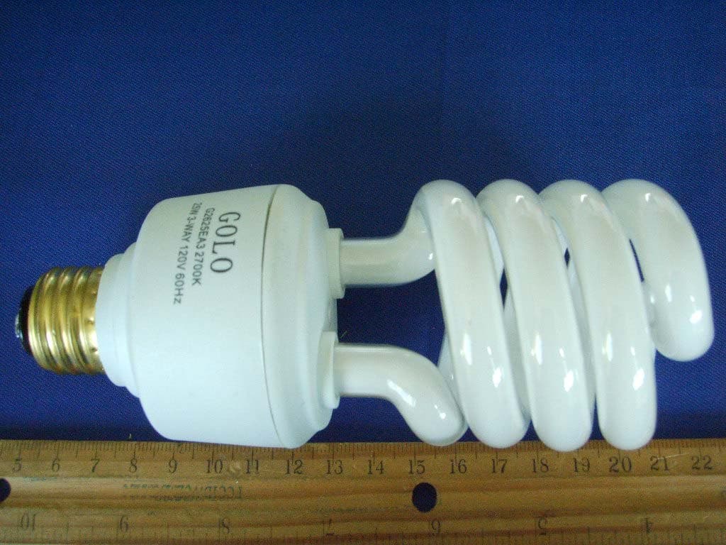
Click to zoom
Application Details
- Equipment Class
- 8CC - Part 18 Consumer Device
- Date of Grant
- Sep 21, 2010
- Application Purpose
- Original Equipment
- Date of Application
- Sep 21, 2010
- Equipment Note
- CFL
- Frequency Range
- 0.06000000 - 0.06000000
- Company
- Golo Chang Company Limited
- Country
- China
Documents & Files
Document Text
Text extracted from the exhibit documents filed with the FCC. Open a document above to read the original.
Users Manual
User manual 1. Purpose Golo’s CFL has implemented three phosphors together into one compact fluorescent. It is a new type of light resource of green environment. The product’s applications are practical for supermarkets, shopping centers, retail stores, and gymnasium. 2. Characteristics Golo’s CFL provides instant start, long-life and high lumen output. The lamp is designed to perform up to the industry standards by using less electricity. Lamp can operate under -18 °C below zero degrees Celsius. From Golo’s testing results shows the self ballast lamp only uses 20% of the electricity and it is compared and equivalent to a regular incandescent bulb. 3. Directions 1) For Safety purposes, the lamp fixture must be powered off before being installed, changed or being cleaned 2) This self ballast lamp cannot be operated with dimmer device. In order to keep the lamp’s high performance it should be used in defined voltage. 3) This Lamp can be performed under environmental areas in temperature from -18° C to 45° C, it cannot be used in enclosed fixture or wet areas. 4) Please check the power, voltage and contacts of the lamp incase the lamp performs abnormal signs such as the light blinking or the light turns off suddenly 5) Do not hold the tube by the hands while changing or cleaning the lamp. The proper way is to hold the lamp by the plastic housing. 4 Warnning This device complies with Part 18 of the FCC Rules. Changes or modifications not expressly approved by the party responsible for compliance could void the user's authority to operate the equipment. This product may cause interference to radio equipment and should not be installed near maritime safety communications equipment or other critical navigation or communication equipment operating between 0.45–30 MHz. If this occurs, please change outlet or move the lamp far away from other appliance. Use only on 120V/60Hz Never disassemble or modify-any changes could void the user’ authority to operate this device. Risk of electric shock-do not use with where directly exposed to water. To prevent burns, do not touch the tube during operation or immediately after switching off. Golo Chang Company Limited 4F, No.50-3, San Min Rd., LuChouCity, TaiBei Hsien, Taiwan, R.O.C.
Cover Letter(s)
SCS-F18: Project and Product Certification Representative Authorization Letter Page 1 of 2 Rev 2.0 2206 Ringwood Avenue San Jose, CA 95131 Tel: 408-526-1188 Fax: 408-526-1088 Email: [email protected] Project and Product Certification Representative Authorization Letter Revision History Reason for Amendment (current / obsolete) From To Approved Date Initial Release (current) 1.0 1.0 Nov-14-2006 Revised wording (current) 1.0 2.0 Sept–25-2007
Cover Letter(s)
SCS-F19: Confidentiality Request Letter Rev 1.0 Nov 14, 2006 Confidentiality Request Letter Revision History Reason for Amendment (current / obsolete) From To Approved Date Initial Release (current) 1.0 1.0 Nov-14-2006
External Photos
APPENDIX III External Photos EUT - General View (G2625EA3) EUT - General View (G2632EA3)
ID Label/Location Info
APPENDIX I FCC ID Label FCC ID: YRP3WAYS
ID Label/Location Info
APPENDIX II FCC ID Label Location FCC ID Label Location
Internal Photos
APPENDIX IV Internal Photos EUT – Uncovered View (G2625EA3) EUT –Components View (G2625EA3) EUT–Solder View (G2625EA3) EUT – Uncovered View (G2632EA3) EUT –Components View (G2632EA3) EUT–Solder View (G2632EA3)
Test Report
Golo Chang Company Limited. FCC ID: YRP3WAYS Report No.BTR66.180.10.074.01 Page 2 of 10 FCC Part 18 Report TABLE OF CONTENTS GENERAL INFORMATION...............................................................................................................................................3 PRODUCT DESCRIPTION FOR EQUIPMENT UNDER TEST (EUT).................................................................................... 3 OBJECTIVE.......................................................................................................................................................................... 3 RELATED SUBMITTAL(S)/GRANT(S)................................................................................................................................. 3 TEST METHODOLOGY........................................................................................................................................................ 3 TEST FACILITY.................................................................................................................................................................... 3 SYSTEM TEST CONFIGURATION................................................................................................................................4 JUSTIFICATION.................................................................................................................................................................... 4 SCHEMATICS / BLOCK DIAGRAM....................................................................................................................................... 4 EQUIPMENT MODIFICATIONS............................................................................................................................................ 4 CONFIGURATION OF TEST SYSTEM.................................................................................................................................. 4 TEST SETUP BLOCK DIAGRAM......................................................................................................................................... 4 CONDUCTED EMISSIONS TEST DAT A......................................................................................................................5 APPLICABLE STANDARD.................................................................................................................................................... 5 MEASUREMENT UNCERTAINTY......................................................................................................................................... 5 EUT SETUP........................................................................................................................................................................ 5 TEST EQUIPMENTS............................................................................................................................................................ 6 TEST PROCEDURE............................................................................................................................................................. 6 SUMMARY OF TEST RESULTS........................................................................................................................................... 6 CONDUCTED EMISSIONS TEST DATA AND PLOTS.......................................................................................................... 7 Golo Chang Company Limited. FCC ID: YRP3WAYS Report No.BTR66.180.10.074.01 Page 3 of 10 FCC Part 18 Report GENERAL INFORMATION Product Description for Equipment under Test (EUT) The Golo Chang Company Limited’s model G2625EA3&G2632EA3 or the “EUT” as referred to in this report is CFL, rated input voltage: AC 120V/60Hz, operation frequency between 40 KHz to 60 KHz. Model G2625EA3 Electrical Power 25W Model G2632EA3 Electrical Power 32W The test data was only good for the test sample. It may have deviation for other test sample. Objective The following test report is prepared on behalf of Golo Chang Company Limited. in accordance with Part 2, Subpart J, and Part 18, Subparts A, B, and C of the Federal Communication Commissions rules and regulations. The objective of the manufacturer is to demonstrate compliance with FCC Part 18 limit requirements for Industrial, Scientific, and Medical Equipment. Related Submittal(s)/Grant(s) No Related Submittals. Test Methodology All measurements contained in this report were conducted with MP-5 1986, FCC Method of measurements of radio noise emission from Industrial, Scientific and Medical equipments. Test Facility All measurement facilities used to collect the data are located at Huatongwei Building , Keji Rd, 12 S, high-Tech Park, Nanshan District, Shenzhen, China. The sites are constructed in conformance with the requirements of ANSI C63.7/634 and CISPR 22, The site was accredited by FCC (662850), A2LA( 2243.01) and CNAL (L1225) Golo Chang Company Limited. FCC ID: YRP3WAYS Report No.BTR66.180.10.074.01 Page 4 of 10 FCC Part 18 Report SYSTEM TEST CONFIGURATION Justification The EUT was tested under normal mode as used by a common (typical) user. Schematics / Block Diagram N/A. Equipment Modifications No modifications were made by BEST TEST SERVICE Shenzhen CO., LTD. to ensure the EUT to comply with the application limits and requirements. Configuration of Test System Test Setup Block Diagram 1.5 Meters E U T P o w e r C o rd E x ten s io n LISN1 Non-conducting table 80 cm above Ground Plane EUT 1 Meter 1.5 Meter Golo Chang Company Limited. FCC ID: YRP3WAYS Report No.BTR66.180.10.074.01 Page 5 of 10 FCC Part 18 Report CONDUCTED EMISSIONS TEST DATA Applicable Standard For the following equipment, when designed to be connected to the public utility (AC) power line the radio frequency voltage that is conducted back onto the AC power line on any frequency or frequencies shall not exceed the limits in the following tables. Compliance with the provisions of this paragraph shall be based on t…
Text truncated - open the document above for the full version.
Test Setup Photos
APPENDIX V Test Setup Photos Test Setup – Front View Test Setup – Side View
Contact Information
Applicant
CK Lin
Test Firm
Shenzhen Huatongwei International Insp. Co., LtdMoffy Yu
Technical Specifications
| # | Rule Parts | Frequency Range | Power Output |
|---|---|---|---|
| 1 | 18 | 0.06 MHz - 0.06 MHz | - |
Other Applications from Golo Chang Company Limited
Sep 27, 2010
Equipment Class
8CC - Part 18 Consumer Device
Sep 21, 2010
Equipment Class
8CC - Part 18 Consumer Device