YRQSEN1Sentinel Camera Unit
Unipar Services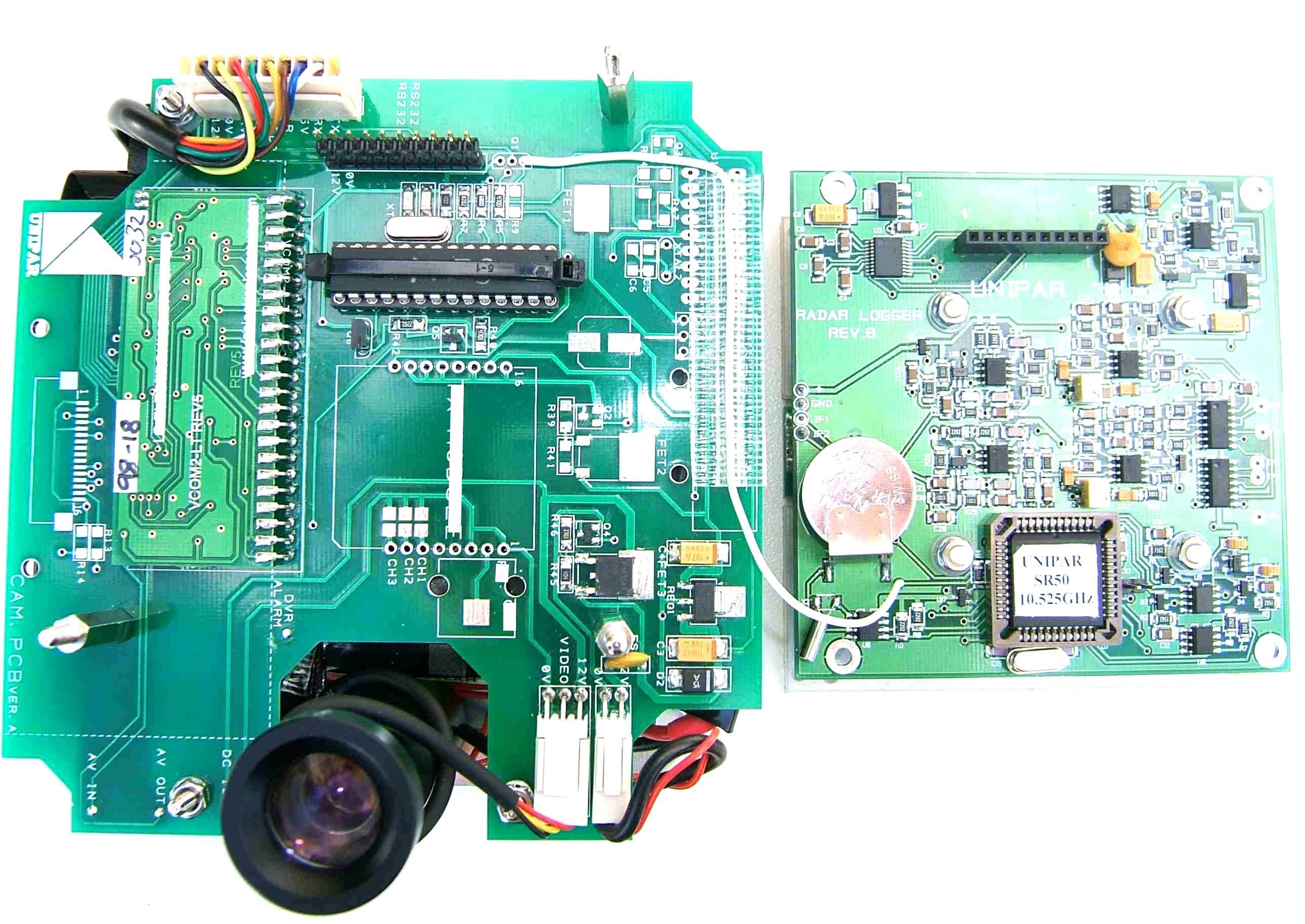
Click to zoom
Application Details
- Equipment Class
- FDS - Part 15 Field Disturbance Sensor
- Date of Grant
- Sep 16, 2010
- Application Purpose
- Original Equipment
- Date of Application
- Sep 16, 2010
- Equipment Note
- Sentinel Camera Unit
- Frequency Range
- 10520.00000000 - 10522.00000000
- Company
- Unipar Services
- Country
- United Kingdom
Documents & Files
Document Text
Text extracted from the exhibit documents filed with the FCC. Open a document above to read the original.
Users Manual
1 UNIPAR UNIPAR SERVICES SENTINEL SENTINEL SENTINEL SENTINEL AUTOMATIC CAMERA SYSTEM Copyright © 2010 Unipar Services Issue 1.0 (September 2010) 2 Contents · Introduction · Connections · Operation · The LCD monitor · Entering the user settings · Taking footage · The DVR (Digital Video Recorder) · Charging · Specifications Unipar Services, The Old Stables, 65 Lower Green Road, Rusthall, Tunbridge Wells Kent, TN4 8TW United Kingdom. 3 INTRODUCTION The Unipar static camera system comprises of a high quality day/night infrared sensitive camera, high capacity battery pack, a solid state Digital Video Recorder, vehicle detection radar and all control circuitry in a single small lightweight package. The unit is easily configured using the supplied remote control with all the settings displayed clearly on the supplied 3.5-inch LCD monitor. The unit can be configured to record vehicles either toward or away over a selected speed (minimum 5 mph) as well as displaying a numeric location code up to 5 characters if required. The same remote control also controls all the functions of the DVR which can be used to play back any of the video files on site. The recorded video file contains both the time and date as well actual live speeds at the instant they occur with the location in the bottom left of the screen. By ejecting the standard SD card from the unit all the recorded video files can be played back on a computer using the software supplied. 4 CONNECTIONS All the connections are via the 6pin socket on the underside and are as follows: Video out – The LCD monitor is plugged into the 6pin connector for viewing/changing the current settings and the sighting of the camera. Charge input – With the unit switched off charge the internal battery pack with the battery charger supplied. OPERATION POWERING UP – Press in the alternate latching power button on the underside of the unit. The unit must have been previously off for it to now power up providing there is sufficient battery voltage. The indicator LED will now illuminate GREEN for approximately 10 seconds whilst the unit does a self-test and the current settings are displayed (connect the monitor to view/change if required). The LED state will then change from continuous GREEN to flashing GREEN every 5 seconds. This indicates the unit is ready to record as per the settings. VIEW OF UNDERSIDE WITH ACCESS COVER REMOVED SD CARD IN DVR PUSH TO EJECT MONITOR & CHARGE CONNECTOR INDICATOR LED ON/OFF POWER BUTTON 5 POWERING DOWN – With the unit on or in standby press in the power button. All LED indicators will switch off. Ensure any recording has finished first. STANBY MODE - Keep the MUTE button on the remote control continually pressed for several seconds observing the red LED flashes as the remote control transmits. The led will suddenly change from flashing to continually on, at which point let go of the MUTE button as the unit is now in standby. The unit will now indicate it is in standby by flashing the red LED every several seconds. Care must be taken to let go of the MUTE button once in standby as the same button is used to power it up again. POWERING UP FROM STANDBY – To wake the unit up from the standby mode press the MUTE button on the remote control and keep it pressed for several seconds observing the red LED flashes as the remote control transmits. After several seconds of flashing the LED will illuminate continually for 5 seconds whilst the current settings are displayed. Once the unit has finished displaying the current settings the LED will change from red to flashing green to indicate the unit is ready to record as per the settings. LOW VOLTAGE INDICATOR – When the internal battery becomes too low (less than 11 volts) the unit goes into low power sleep mode to protect the battery from deep discharge. This is indicated by the LED flashing RED then GREEN every 10 seconds. The unit must be then switched off via the on/off switch on the underside and charged up. CONFIRMING THE CURRENT SETTINGS – When the unit is first powered up the current over-speed, direction and location code settings are displayed. These can however be verified and changed if desired at any time by pressing and holding the ENT (enter) button) without the necessity for the unit to be switched off and on again. ACCESS COVER - This provides a watertight cover to protect and conceal the connector and SD card. THE LCD MONITOR The camera system is supplied with a 3.5-inch portable LCD monitor so the camera can be aimed correctly and the operational settings for both the system and the DVR can be viewed. Refer to the operating manual enclosed with the monitor for charging and maintenance instructions. 6 ENTERING THE USER SETTINGS REMOTE CONTROL BUTTONS FORWARD ARROW – Advances onto the next character to change. The black background of the character is removed to identify which character has been selected. THE UP & DOWN ARROWS SELECT CHARACTERS 0 to 9 THE BACK & FWD ARROWS MOVE TO PREVIOUS OR NEXT POSITION. PRESS & HOLD THE MUTE BUTTON FOR STANDBY/WAKE UP. PRESS & HOLD THE ENT BUTTON TO DISPLAY CURRENT THRESHOLD SETTINGS. CLEAR BACKGROUND IDENTIFIES SELECTED CHARACTER. OVERSPEED, DIRECTION & LOCATION CODE ARE ALL SET USING THE REMOTE CONTROL. 7 REVERSE ARROW – Goes back one step. The black background of the character is removed to identify which character has been selected. UP ARROW – Changes the character to the next one in the sequence i.e. if it was 1 it would now change to 2 and if pressed again change to 3 etc. The black background of the character is momentarily restored as it changes so it can be easily read. DOWN ARROW - Changes the character to the previous one in the sequence i.e. if it was 8 it would now change to 7 and if pressed again change to 6 etc. The black background of the character is momentarily restored as it changes. OVERSPEED – The speed over which the unit will start to record (assuming it is above 5 mph and the direction is correct). The radar is factor…
Text truncated - open the document above for the full version.
Attestation Statements
UNIPARSERVICES THESPEEDDETECTIONSPECIALISTS LETTEROF AGENCY 10 September2010 TRaCGlobal 100FrobisherBusinessPark LeighSintonRoad Malvern Worcestershire WR141BX UK ToWhomIt MayConcern: Wecertifythatwearenotsubjectto denialof federalbenefits,thatincludesFCCbenefits,pursuantto Section5301of theAnti-DrugAbuseACTof 1988,U.S.C.862.Further,noparty,asdefinedin 47CFR 1.2002(b),to theapplication,is subjectto denialof federalbenefits,thatincludesFCCbenefits. Thankyouforyourattentionto thismatter. Thankyouforyourattentionto thesematters. Yoursfaithfully UniparServices G- UOI\JATitANJj\Jt-0TtldbJ~ www.uniparservices.com TRL51 F047issQ2B [email protected] THEOLDSTABLES65 LOWERGREENROADRUSTHALLTUNBRIDGEWELLSKENTTN48TW
Cover Letter(s)
UNIPARSERVICES THESPEEDDETECTIONSPECIALISTS REQUESTFORCONFIDENTIALITY INACCORDANCEWITHFCCRULE0.459 13 September2010 TRaCGlobal 100FrobisherBusinessPark LeighSintonRoad Malvern Worcestershire WR141BX UK RE:CertificationApplication FCCID:YRQSEN1 ToWhomIt MayConcern: Pleasebeadvisedthatthefollowinginformationis to beheldconfidentialonbehalfof UniparServices. •Schematics •PartsList •Operational/Technicaldescription •Blockdiagram TheapplicationcontainstechnicalinformationwhichUniparServicesdeemsto betradesecretsand propriety.If madepublic,theinformationmightbeusedto thedisadvantageof theapplicantin the marketplace. Thankyouforyourattentionto thismatter. Yoursfaithfully UniparServices (j. UoNA-\H AtVb\Jf\.)THOQIv~ www.uniparservices.com ...lRL51 F050iss02B. [email protected] THEOLDSTABLES65 LOWERGREENROADRUSTHALLTUNBRIDGEWELLSKENTTN48TW
External Photos
EXTENAL /INTERNAL PHOTOS AND DIMENSIONS EXTERNAL PHOTO FRONT VIEW BACK VIEW UNIPAR SERVICES RESTRICTED: - COMMERCIAL IN CONFIDENCE 130mm 130mm 95mm UNDERSIDE VIEW INTERNAL PHOTOS TOP VIEW OF SENTINEL COMPLETE AND OUT OF ITS HOUSING. UNIPAR SERVICES RESTRICTED: - COMMERCIAL IN CONFIDENCE VIEW OF SENTINEL WITH FRONT COVER REMOVED. FRONT VIEW OF SENTINEL COMPLETE AND OUT OF ITS HOUSING. SIDE VIEW OF SENTINEL COMPLETE AND OUT OF ITS HOUSING. TOP VIEW OF SENTINEL WITH RADAR PCB REMOVED UNIPAR SERVICES RESTRICTED: - COMMERCIAL IN CONFIDENCE
ID Label/Location Info
FCC LABEL ARTWORK AND POSITION INCLUDING WARNING STATEMENT MODEL:SEN1 MANUFACTURED BY: UNIPAR SERVICES Position of the label on the rear top left-hand corner of the Sentinel. MADE IN THE U.K. RECHARGEABLE NiMH BATTERY. MUST BE RECYCLED OR DISPOSED OF PROPERLY. FCC ID:YRQSEN1 30mm CHARACTER HEIGHT 2mm 21mm 12mm 25mm
Internal Photos
EXTENAL /INTERNAL PHOTOS AND DIMENSIONS EXTERNAL PHOTO FRONT VIEW BACK VIEW UNIPAR SERVICES RESTRICTED: - COMMERCIAL IN CONFIDENCE 130mm 130mm 95mm UNDERSIDE VIEW INTERNAL PHOTOS TOP VIEW OF SENTINEL COMPLETE AND OUT OF ITS HOUSING. UNIPAR SERVICES RESTRICTED: - COMMERCIAL IN CONFIDENCE VIEW OF SENTINEL WITH FRONT COVER REMOVED. FRONT VIEW OF SENTINEL COMPLETE AND OUT OF ITS HOUSING. SIDE VIEW OF SENTINEL COMPLETE AND OUT OF ITS HOUSING. TOP VIEW OF SENTINEL WITH RADAR PCB REMOVED UNIPAR SERVICES RESTRICTED: - COMMERCIAL IN CONFIDENCE
Test Report
Total number of pages: 37 TRaC Wireless Test Report:TTR-000623WUS1 Applicant:Unipar Services Apparatus:Sentinel Camera Unit Specification(s):CFR47 Part 15 July 2008 Purpose of Test: Certification FCCID: YRQSEN1 Authorised by: : Radio Product Manager Issue Date:8 th September 10 KTL EMC Test Report: ?G????G??1 2 Authorised Copy Number: PDF Radio Test Report: TTR-000623WUS1 3 Contents Section 1:Introduction4 1.1General4 1.2Tests Requested By5 1.3Manufacturer5 1.4Apparatus Assessed5 1.5Test Result Summary6 1.6Notes Relating To The Assessment7 1.7Deviations from Test Standards7 Section 2:Measurement Uncertainty8 2.1Measurement Uncertainty Values8 Section 3:Modifications10 3.1Modifications Performed During Assessment10 Appendix A:Formal Emission Test Results11 A1Transmitter Intentional Emission Radiated12 A2Radiated Electric Field Emissions13 Appendix C: Additional Test and Sample Details24 Appendix D:Additional Information30 Appendix E:Calculation of the duty cycle correction factor31 Appendix F:Photographs and Figures32 Radio Test Report: TTR-000623WUS1 4 Section 1:Introduction 1.1General This report contains an assessment of an apparatus against Electromagnetic Compatibility Standards based upon tests carried out on samples submitted to the Laboratory. Test performed by:TRaC Telecoms & Radio[ ] Unit E South Orbital Trading Park Hedon Road Hull, HU9 1NJ. United Kingdom. Telephone:+44 (0) 1482 801801 Fax:+44 (0) 1482 801806 TRaC Telecoms & Radio[X] Unit 1 Pendle Place Skelmersdale West Lancashire, WN8 9PN United Kingdom Telephone:+44 (0) 1695 556666 Fax:+44 (0) 1695 577077 Email:[email protected] Web site:http://www.tracglobal.com Tests performed by:D. Winstanley Report author:D. Winstanley This report must not be reproduced except in full without prior written permission from TRaC Telecoms & Radio. Radio Test Report: TTR-000623WUS1 5 1.2Tests Requested By This testing in this report was requested by : Unipar Services The Old Stables 65 Lower Green Road Rushall Tunbridge Wells Kent TN4 8TW 1.3Manufacturer As Above 1.4Apparatus Assessed The following apparatus was assessed between 26 th – 30 th July 2010: Sentinel Camera unit. The SentinelCameraunit is a speed detection device with built-in digital camera for recording video of speeding events. Radio Test Report: TTR-000623WUS1 6 1.5Test Result Summary Full details of test results are contained within Appendix A. The following table summarises the results of the assessment. The statements relating to compliance with the standards below apply ONLYas qualified in the notes and deviations stated in sections 1.6 to 1.7 of this test report. Full details of test results are contained within Appendix A. The following table summarises the results of the assessment. Test TypeRegulation Measurement standard Result Spurious Emissions Radiated <1000MHz Title 47 of the CFR: Part 15 Subpart (c) 15.209 ANSI C63.10Pass Spurious Emissions Radiated >1000MHz Title 47 of the CFR: Part 15 Subpart (c) 15.209& 12.245 ANSI C63.10Pass Intentional Emission Frequency Title 47 of the CFR: Part 15 Subpart (c) 15.245 ANSI C63.10Pass Intentional Emission Field Strength Title 47 of the CFR: Part 15 Subpart (c) 15.245 ANSI C63.10Pass Intentional Emission Band Occupancy Title 47 of the CFR: Part 15 Subpart (c) 15.245 ANSI C63.10Pass Unintentional Radiated Spurious Emissions Title 47 of the CFR: Part 15 Subpart (b) 15.109 ANSI C63.10Pass Antenna Arrangements Integral: Title 47 of the CFR: Part 15 Subpart (c) 15.203 -Pass Antenna Arrangements External Connector Title 47 of the CFR: Part 15 Subpart (c) 15.204 -Pass Restricted Bands Title 47 of the CFR: Part 15 Subpart (c) 15.205 -Pass Maximum Frequency of Search Title 47 of the CFR: Part 15 Subpart (c) 15.33 -Pass Extrapolation Factor Title 47 of the CFR: Part 15 Subpart (c) 15.31(f) -Pass Abbreviations used in the above table: CFR: Code of Federal RegulationsANSI: American National Standards Institution REFE: Radiated Electric Field EmissionsPLCE: Power Line Conducted Emissions Radio Test Report: TTR-000623WUS1 7 1.6Notes Relating To The Assessment With regard to this assessment, the following points should be noted: The results contained in this report relate only to the items tested and were obtained in the period between the date of initial receipt of samples and the date ofissue of the report. The apparatus was set up and exercised using the configurations, modes of operation and arrangements defined in this report only. Particular operating modes, apparatus monitoring methods and performance criteria required by the standards tested to have been performed except where identified in Section 1.7 of this test report (Deviations from Test Standards). For emissions testing, throughout this test report, “Pass” indicates that the results for the sample as tested were below the specified limit (refer also to Section 2, Measurement Uncertainty). Where relevant, the apparatus was only assessed using the monitoring methods and susceptibility criteria defined in this report. All testing with the exception of testing at the Open Area Test Site was performed under the following environmental conditions: Temperature: 17 to 23 C Humidity : 45 to 75 % Barometric Pressure: 86 to 106 kPa All dates used in this report are in the format dd/mm/yy. This assessment has been performed in accordance with the requirements of ISO/IEC 17025. 1.7Deviations from Test Standards There were no deviations from the standards tested to. Radio Test Report: TTR-000623WUS1 8 Section 2:Measurement Uncertainty 2.1Measurement Uncertainty Values For the test data recorded in accordance with note (iii) of Section 2.1 the following measurement uncertainty was calculated: Radio Testing – General Uncertainty Schedule All statements of uncertainty are expanded standard uncertaintyusing a coverage factor of 1.96 to give a 95% confidence where no required test level exists. [1] Adjacent Channel Power Uncertainty in test result = 1.86dB [2] Carrier Power Uncertainty in t…
Text truncated - open the document above for the full version.
Contact Information
Applicant
Jonathan Dunthorne
Test Firm
Element Materials Technology Warwick LtdMax Leach
Technical Specifications
| # | Rule Parts | Frequency Range | Power Output |
|---|---|---|---|
| 1 | 15.245 | 10.52 GHz - 10.52 GHz | - |