YSGDR9550Implantable cardioverter defibrillator
SORIN CRM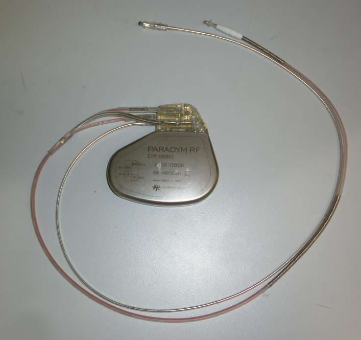
Click to zoom
Application Details
- Equipment Class
- TNT - Licensed Non-Broadcast Transmitter Worn on Body
- Date of Grant
- Nov 13, 2012
- Application Purpose
- Original Equipment
- Date of Application
- Jul 02, 2012
- Equipment Note
- Implantable cardioverter defibrillator
- Frequency Range
- 402.00000000 - 405.00000000
- Company
- SORIN CRM
- Country
- France
Documents & Files
Document Text
Text extracted from the exhibit documents filed with the FCC. Open a document above to read the original.
Users Manual
TABLE OF CONTENTS 1. General description .................................................................... 6 2. Indications ................................................................................... 6 3. Contraindications ....................................................................... 6 4. Warnings and precautions ........................................................ 7 4.1. Risks related to medical environment ........................... 8 4.2. Sterilization, storage and handling .............................. 10 4.3. Implantation and device programming ........................ 11 4.4. Lead evaluation and lead connection .......................... 12 4.5. Generator explant and disposal ................................... 13 5. Adverse events ......................................................................... 14 5.1. Defender study ............................................................... 14 5.2. SafeR study .................................................................... 17 6. Clinical studies ......................................................................... 19 6.1. Defender study ............................................................... 19 6.2. SafeR study .................................................................... 23 7. Patient selection and treatment .............................................. 28 7.1. Individualization of treatment ....................................... 28 7.2. Specific patient populations ......................................... 29 8. Patient counselling information .............................................. 30 9. Conformance to standards ...................................................... 30 10. Physician guidelines ................................................................ 34 10.1. Physician training .......................................................... 34 10.2. Directions for use........................................................... 34 10.3. Maintaining device quality ............................................ 34 11. Patient information ................................................................... 35 12. How supplied ............................................................................ 35 12.1. Sterility ............................................................................ 35 12.2. Warranty and replacement policy ................................ 35 13. Device description.................................................................... 35 14. Implant procedure .................................................................... 38 14.1. Necessary equipment .................................................... 38 14.2. Packaging ....................................................................... 39 14.3. Optional equipment ....................................................... 39 14.4. Before opening the package ......................................... 39 14.5. Prior to implantation ...................................................... 40 14.6. Device placement ........................................................... 40 14.7. Choosing the type of lead ............................................. 41 14.8. Measurement of thresholds at implant ........................ 42 14.9. Lead connection............................................................. 43 14.10. Device implantation ....................................................... 45 14.11. Tests and programming ................................................ 45 15. Special modes .......................................................................... 46 15.1. Safety mode (nominal values) ...................................... 46 15.2. Magnet mode .................................................................. 46 15.3. Response in the presence of interference .................. 47 15.4. Detection characteristics in the presence of electromagnetic fields ................................................... 48 15.5. Protection against short-circuits .................................. 49 16. Main functions .......................................................................... 49 16.1. Automatic lead measurements ..................................... 49 16.2. Atrial tachyarrhythmia management ............................ 49 16.3. Ventricular tachyarrhythmia management .................. 50 16.4. Pacing ............................................................................. 51 16.5. Sensing ........................................................................... 51 16.6. Follow-up functions ....................................................... 52 16.7. Remote Monitoring function ......................................... 53 17. Patient follow-up ....................................................................... 56 17.1. Follow-up recommendations ........................................ 56 17.2. Holter Function ............................................................... 57 17.3. Elective Replacement Indicator (ERI) .......................... 58 17.4. Explantation .................................................................... 59 17.5. Defibrillator identification ............................................. 60 18. Physical characteristics .......................................................... 61 18.1. Materials used ................................................................ 61 19. Electrical characteristics ......................................................... 62 19.1. Table of delivered shock energy and voltage ............. 63 19.2. Battery ............................................................................. 64 19.3. Longevity ........................................................................ 64 20. Programmable parameters ...................................................... 66 20.1. Antibradycardia pacing ................................................. 66 20.2. Ventricular tachyarrhythmia detection ........................ 71 2…
Text truncated - open the document above for the full version.
Cover Letter(s)
1 COVER LETTER SORIN – PARADYM RF FCC ID YSGDR9550 April 10 th 2012 This report concerns : Original Grant ___X____ Class II change __________ SubPart C certification ___X____ *Class A verification _______ Class I change _______ Equipment type : Modular transmitter Request issue of grant : _X_ Immediately upon completion of review ___ Defer grant per 47 CFR 0.457(d)(1)(ii) until ____ date _____. Company Name agrees to notify the Commission by _____date_____ of the intended date of announcement of the product so that the grant can be issued on that date. Confidentiality of grant : ___ Applicant requests the existence of this grant to be kept confidential until ____date____. The announcement of this product before this date via freedom of information would be detrimental to Company Name, and therefore must be considered a business secret. Public announcement of this product will not be made prior to this date. (Max. 60 days after grant issued). Limits used : (check one) CISPR 22 _______ ___________ Part 15 _______ X ___________ Measurement procedure used is ANSI C63.4-2003 unless another is specified. Other test procedure : ____________________________________________________ Application for verification Applicant for this device Prepared by : Philippe SISSOKO LCIE 33 avenue du Général Leclerc 92260 Fontenay-Aux-Roses – France Ph. : +33 1 40 95 60 60 Fax : +33 1 40 95 89 10 e-mail : [email protected] FRN : 0017404559 Cécile de JESO SORIN CRM Parc d’affaires NOVEOS 4, Avenue Réamur 92140 Clamart - France Ph. : +33 1 46 01 33 48 e-mail: [email protected] FRN : 0020190344 Not to be filed with Equipment Authorization Branch of FCC unless requested Report format prepared by the Information Technology Industry Council (ITI) ESC-5 and reviewed by FCC staff in 1994
External Photos
PARADYM RF DR 9550 FCC ID: YSGDR9550 – External photograph
Internal Photos
PARADYM RF DR 9550 FCC ID: YSGDR9550 – Internal photographs
Operational Description
FF00929A Document reference MISC444B Dept. internal ref. - Page 1/16 This document contains information which Sorin Group deems CONFIDENTIAL and PROPRIETARY; therefore it shall not to be used, duplicated, or disclosed in whole or in part without the prior written consent of Sorin Group. OFFICIAL DOCUMENT Document type: Technical Note Document reference MISC444B Dept. internal ref. - Project: RMS Department: R&D Reserved to the assistant filing the document Filed in IntraELA by : on Original in: Clamart Title: Smartview Monitor and IMD System Description Abstract: High-level description of the structure and operation of the Smartview Monitor and associated Implantable Medical Device Name Function Signature Date Prepared by Fabio Belletti SM project leader Nov. 1 st , 2011 Reviewed by Philippe Barou IMD project leader Reviewed by Thierry Scordilis RF Function Leader Reviewed by Cecile de Jeso SM & Syndeli RF RA Engineer Reviewed by Approved by Daniel Kroiss RF team Manager FF00929A Document reference MISC444B Dept. internal ref. - Page 2/16 This document contains information which Sorin Group deems CONFIDENTIAL and PROPRIETARY; therefore it shall not to be used, duplicated, or disclosed in whole or in part without the prior written consent of Sorin Group. OFFICIAL DOCUMENT REVISION HISTORY Rev. Sect. Change Author Release date A 1 Initial release Fabio Belletti 09-Mar-2009 2 Functional description added Fabio Belletti 25-Feb-2010 3 IMD description add-on Philippe Barou 01-Mar-2010 4 SM software test scheme Fabio Belletti 05-Mar-2010 5 Transfer in FF929 format Cecile de Jeso 18-Mar-2010 6 New ICD image, approver Fabio Belletti 19-Mar-2010 B § 1.3.3 Block Diagram removed (FCC req) Everywhere: Home Monitor (or SM) updated to Smartview Monitor (or SM) Everywhere: MICS updated to MedRadio Georges Wanderstok FF00929A Document reference MISC444B Dept. internal ref. - Page 3/16 This document contains information which Sorin Group deems CONFIDENTIAL and PROPRIETARY; therefore it shall not to be used, duplicated, or disclosed in whole or in part without the prior written consent of Sorin Group. OFFICIAL DOCUMENT TABLE OF CONTENT 1. Introduction ............................................................................................................... 4 1.1. Purpose ................................................................................................................. 4 1.2. Acronyms ............................................................................................................. 4 1.3. System description ............................................................................................... 5 1.3.1. SM Operating modes .................................................................................... 5 1.3.2. IMD Operating modes .................................................................................. 5 1.3.3. IMD Hardware .............................................................................................. 6 2. Smartview Monitor Functional Descritption ......................................................... 6 2.1. Smartview Monitor Operation ............................................................................. 6 2.2. Smartview Monitor Main Features ...................................................................... 7 2.2.1. Functional Description of the Smartview Monitor software ........................ 7 2.2.2. User Interface ................................................................................................ 9 2.2.3. Normal Operation ......................................................................................... 9 2.2.4. On-Demand Follow-Up ................................................................................ 9 2.2.5. Alerts ........................................................................................................... 10 2.2.6. SM-BO communication .............................................................................. 10 2.2.7. SM-IMD communication ............................................................................ 11 2.2.8. Self test ........................................................................................................ 11 2.2.9. Upgrades ..................................................................................................... 12 3. Smartview Monitor Test ......................................................................................... 12 3.1. Smartview Monitor TEST Utilities .................................................................... 13 3.2. Smartview Monitor Basic operation .................................................................. 13 3.3. FailureS and recovery ......................................................................................... 15 3.3.1. Admitted failures ........................................................................................ 15 3.3.2. Not Admitted failures ................................................................................. 15 3.3.3. Faults Recovery .......................................................................................... 15 4. IMD Test .................................................................................................................. 16 FF00929A Document reference MISC444B Dept. internal ref. - Page 4/16 This document contains information which Sorin Group deems CONFIDENTIAL and PROPRIETARY; therefore it shall not to be used, duplicated, or disclosed in whole or in part without the prior written consent of Sorin Group. OFFICIAL DOCUMENT 1. INTRODUCTION 1.1. PURPOSE The purpose of the present document is to provide a high-level description of the structure and operation of the following sub-systems of Sorin Remote Monitoring System: the Smartview Monitor and the Implantable Medical Device. The Smartview Monitor (SM) is intended to collect patient’s clinical data from an Implantable Medical Device (IMD) and transfer them to data ma…
Text truncated - open the document above for the full version.
RF Exposure Info
OFFICIAL DOCUMENT Document Name / Nome documento / Nom du document MISC513C FF00929B - DHF Page 1/23 This document contains information which Sorin Group deems CONFIDENTIAL and PROPRIETARY; therefore it shall not to be used, duplicated, or disclosed in whole or in part without the prior written consent of Sorin Group. Type of document / Tipo di documento / Type de document Technical Note Project PARADYM RF JPN RDY Department: ASIC Original stored in: Meylan Department Internal Ref: Title: SAR SIMULATION REPORT Filed in Intraprod on : By: Abstract: This document deals with the SAR simulations results performed on the 4 different headers of ParadymRF and ParadymRF JPN RDY platforms (CRTD SonR / CRTD / DR / VR). Name Function Signature Date Prepared by H. Guidetti RF system Engineer Jan 31th, 2012 Verified by T.Scordilis RF system Engineer Verified by C.de Jeso RA Project Leader Verified by O.Varomme QA Project Leader Approved by P.Barou R&D Project Leader OFFICIAL DOCUMENT Document Name / Nome documento / Nom du document MISC513C FF00929B - DHF Page 2/23 This document contains information which Sorin Group deems CONFIDENTIAL and PROPRIETARY; therefore it shall not to be used, duplicated, or disclosed in whole or in part without the prior written consent of Sorin Group. HISTORY / STORIA / HISTORIQUE Rev. Change Reason for Change Release date A - Document creation May 20 th , 2010 B Introduction of Paradym RF JPN RDY Justify SAR previous simulation outcomes are still relevant for the new ZL70441 RF module embedded in Paradym RF JPN RDY devices Feb 2 nd , 2012 C In section 10.2, FCC OET Bulletin 65, supplement C” instead of “FCC OET Bulletin 65 supplement 65” Erroneous reference correction OFFICIAL DOCUMENT Document Name / Nome documento / Nom du document MISC513C FF00929B - DHF Page 3/23 This document contains information which Sorin Group deems CONFIDENTIAL and PROPRIETARY; therefore it shall not to be used, duplicated, or disclosed in whole or in part without the prior written consent of Sorin Group. TABLE OF CONTENT / INDICE / TABLE DES MATIERES 1. INTRODUCTION ............................................................................................................................. 5 2. JUSTIFICATION FOR PARADYM RF JPN RDY ...................................................................... 5 3. ABREVIATIONS .............................................................................................................................. 5 4. SAR DEFINITION ............................................................................................................................ 6 5. REFERENCE STANDARDS ........................................................................................................... 6 6. SAR LIMITS...................................................................................................................................... 7 6.1. GENERAL : ICNIRP LEVELS .................................................................................................. 7 6.2. EUROPE REGION ..................................................................................................................... 7 6.3. USA REGION ............................................................................................................................. 7 7. METHODS FOR SAR CALCULATION ....................................................................................... 8 8. CST MWS SAR CALCULATION METHOD ............................................................................... 9 9. COMPUTATIONAL RESOURCES ............................................................................................... 9 10. GENERAL COMMON SIMULATION CONDITIONS ........................................................... 9 10.1. LEAD CONFIGURATION .................................................................................................... 9 10.2. TISSUE PROPERTIES ......................................................................................................... 10 10.3. SIMULATION VOLUME .................................................................................................... 11 10.4. BOUNDARY CONDITIONS ............................................................................................... 11 10.5. METAL properties ................................................................................................................ 11 10.6. EXCITATION PORT............................................................................................................ 12 10.7. INPUT POWER .................................................................................................................... 13 10.8. CHOICE OF FREQUENCY ................................................................................................. 13 10.9. RF ANTENNA ...................................................................................................................... 13 10.10. MESH DENSITY .................................................................................................................. 14 10.11. CONVERGENCE CRITERIA .............................................................................................. 15 11. CRTD-SonR ICD SIMULATION ............................................................................................. 16 11.1. DEVICE AND SIMULATION VOLUME ........................................................................... 16 11.2. SAR SIMULATION RESULTS ........................................................................................... 16 11.2.1. EUROPE : 10G CUBE TISSUE ....................................................................................... 16 11.2.2. USA : 1G CUBE TISSUE ................................................................................................. 16 11.3. CONCLUSIONS ................................................................................................................... 17 12…
Text truncated - open the document above for the full version.
Test Report
Accréditation N° 1-0312 Scope available on www.cofrac.fr TEST REPORT RADIO Number 112624-622708-L-Cr2012-05-16 Composition of document 19 pages Standards ETSI EN 300328 V1.7.1 FCC RULES PART 15 IC RADIO STANDARDS RSS-210 ARIB STD-T66 V2.1 Issued to SORIN CRM Parc d'affaires NOVEOS 4, Avenue Réaumur 92140 Clamart Cedex , FRANCE Mme DE JESO Apparatus under test Syndeli RF implantable cardioverter defibrillator Trade mark SORIN Group Manufacturer SORIN BIOMEDICA CRM Type PARADYM RF — DR model 9550 Serial number 148YX02B Test date 2012/03/21 and 2012/03/26 to 2012/03/30 Tests performed by Stéphane PHOUDIAH & Laurent DENEUX Test site Fontenay Aux Roses & Ecuelles File issued on 2012/05/16 File corrected on 2012/05/16 File initialy issued on 2012/04/18 Written by : Approved by : Stéphane PHOUDIAH & Laurent DENEUX Marc CANCOUET Tests operator Technical manager This document shall not be reproduced, except in full, without the written approval of the LCIE. This document contains results related only to the item tested. It does not imply the conformity of the whole production to the items tested. Unless otherwise specified, the decision of conformity takes into account the uncertainly of measures. This document doesn’t anticipate any certification decision. The COFRAC accreditation only attests the technical capability of the testing laboratory for the tests covered by the accreditation. Only tests not covered by the COFRAC accreditation are marked with asterisk (*) TEST REPORT N° 112624-622708-L-Cr2012-05-16 Page 2 SUMMARY 1. TEST PROGRAM ............................................................................................................................... 3 2. EQUIPMENT DESCRIPTION .............................................................................................................. 5 3. RECEIVER SPURIOUS EMISSIONS .................................................................................................. 8 4. RADIATION EMISSIONS .................................................................................................................. 11 5. TEST EQUIPMENT LIST .................................................................................................................. 13 6. UNCERTAINTIES CHART ................................................................................................................ 14 7. ANNEX 1 (GRAPHICS) ..................................................................................................................... 15 8. ANNEX 2 (FLUID DATA SHEET MSL 450) ....................................................................................... 17 TEST REPORT N° 112624-622708-L-Cr2012-05-16 Page 3 1. TEST PROGRAM References Standards: ETSI EN 300328 V1.7.1 ERC Recommendation 70-03 ARIB STD-T66 V2.1 FCC RULES PART 15 IC RADIO STANDARDS RSS-210 Transmitter requirement: Clause (ETSI EN 300 328) Test Description TEST RESULT - Comments 4.2.1 – FHSS modulation N/A (Receiver Equipment) 5.7.2 – Equivalent Isotropic Radiated Power N/A (Receiver Equipment) 5.7.3 – Maximum EIRP spectral density N/A (Receiver Equipment) 5.7.4 – Frequency Range N/A (Receiver Equipment) 5.7.5 – Transmitter Spurious Emissions N/A (Receiver Equipment) Clause (ARIB STD-T66) Test Description TEST RESULT - Comments 3.1 (1) – Communication method PASS 3.1 (2) – Contents of communication PASS 3.1 (3) – Frequency band PASS 3.1 (4) – Environmental operating conditions PASS 3.2 (1) – Modulation system N/A (Receiver Equipment) 3.2 (2) – Antenna power N/A (Receiver Equipment) 3.2 (4) – Frequency tolerance N/A (Receiver Equipment) 3.2 (6) – Spurious emissions intensity N/A (Receiver Equipment) 3.2 (7) – Occupied bandwidth N/A (Receiver Equipment) 3.2 (8) – Spread bandwidth N/A (Receiver Equipment) 3.2 (9) – Process gain N/A (Receiver Equipment) 3.2 (10) – Number of carrier within 1MHz bandwidth in OFDM N/A (Receiver Equipment) 3.2 (11) – Dwell time N/A (Receiver Equipment) 3.6 (2) – Antenna Characteristics N/A (Receiver Equipment) Clause (FCC PART 15) Test Description TEST RESULT - Comments Power line conducted emissions N/A (Receiver Equipment) Channel separation N/A (Receiver Equipment) Time of Occupancy N/A (Receiver Equipment) 20dB Occupied bandwidth N/A (Receiver Equipment) Peak Power Output N/A (Receiver Equipment) Radiated emissions N/A (Receiver Equipment) TEST REPORT N° 112624-622708-L-Cr2012-05-16 Page 4 Clause (RSS 210) Test Description TEST RESULT - Comments Power line conducted emissions N/A (Receiver Equipment) Channel separation N/A (Receiver Equipment) Time of Occupancy N/A (Receiver Equipment) 20dB Occupied bandwidth N/A (Receiver Equipment) Peak Power Output N/A (Receiver Equipment) Radiated emissions N/A (Receiver Equipment) Receiver requirement: Clause (ETSI EN 300 328) Test Description TEST RESULT - Comments 8.6 –Receiver Spurious Emissions PASS Clause (ARIB STD-T66) Test Description TEST RESULT - Comments 3.3 (1) – Receiver spurious radiation PASS Clause (FCC 15.247) Test Description TEST RESULT - Comments Radiated emissions PASS Clause (RSS 210) Test Description TEST RESULT - Comments Radiated emissions PASS PASS: EUT complies with standard’s requirement FAIL: EUT does not comply with standard’s requirement N/A: Not Applicable N/P: Test Not Performed TEST REPORT N° 112624-622708-L-Cr2012-05-16 Page 5 2. EQUIPMENT DESCRIPTION 2.1. HARDWARE IDENTIFICATION Equipment under test (EUT): The EUT is housed in a single cabinet that cannot be readily opened because the enclosure is hermetically sealed. Input/output: -Human torso simulator -Fluid corresponding to human tissue characteristics at that frequency. -Lead IS-1 LV -Lead IS-1 RV -Lead DF-1 SVC -Lead DF-1 RV Equipment information: - Modulation technology: FHSS modulation - Modulation type: OOK - Operating frequency range: 2400MHz to 2483,5MHz - Type of the equipment: stand-alone equipment - Extreme temperature range: -Tmin: 25°C -Tnom: 37°C -Tmax: 45°C - Extreme test source voltage: -Vnom: BOL:…
Text truncated - open the document above for the full version.
Test Report
TEST REPORT RADIO Number 112624-622708-K-Cr2012-10-22 Composition of document 45 pages Standards ETSI EN 301 839-1 V1.2.1 ETSI EN 301 839-2 V1.3.1 FCC RULES PART 95I FCC RULES PART 15 FCC RYLES PART 2 IC RADIO STANDARDS RSS-243 Specified low-power radio equipment (Item 8 of Article 2 Paragraph 1 of Certification Ordinance) Issued to SORIN CRM Parc d'affaires NOVEOS 4, Avenue Réaumur 92140 Clamart Cedex , FRANCE Mme DE JESO Apparatus under test Syndeli RF implantable cardioverter defibrillator Trade mark SORIN Group Manufacturer SORIN BIOMEDICA CRM Type PARADYM RF — DR model 9550 Serial number 148YX02B Test date 2012/03/21 and 2012/03/26 to 2012/03/30 Tests performed by Stéphane PHOUDIAH & Laurent DENEUX Test site Fontenay Aux Roses & Ecuelles File issued on 2012/10/22 File corrected on 2012/10/22 File initialy issued on 2012/04/18 Written by : Approved by : Stéphane PHOUDIAH & Laurent DENEUX Marc CANCOUET Tests operator Technical manager This document shall not be reproduced, except in full, without the written approval of the LCIE. This document contains results related only to the item tested. It does not imply the conformity of the whole production to the items tested. Unless otherwise specified, the decision of conformity takes into account the uncertainly of measures. TEST REPORT N° 112624-622708-K-Cr2012-10-22 Page 2 SUMMARY 1. TEST PROGRAM ............................................................................................................................... 3 2. EQUIPMENT DESCRIPTION .............................................................................................................. 5 3. FREQUENCY ERROR & FREQUENCY STABILITY ........................................................................... 8 4. EFFECTIVE RADIATED POWER, MAXIMUM TRANSMITTER POWER & ANTENNA POWER ........ 9 5. EMISSION BANDWIDTH & OCCUPIED BANDWIDTH ..................................................................... 10 6. SPURIOUS EMISSIONS OF TRANSMITTER & TOLERANCE OF UNWANTED EMISSION INTENSITY ................................................................................................................................................... 11 7. UNWANTED RADIATION ................................................................................................................. 14 8. RECEIVER SPURIOUS RADIATION & SECONDARY RADIATED EMISSION ................................ 17 9. RADIATION EMISSIONS .................................................................................................................. 20 10. TEST EQUIPMENT LIST .................................................................................................................. 22 11. UNCERTAINTIES CHART ................................................................................................................ 23 12. ANNEX 1 (GRAPHS) ........................................................................................................................ 24 13. ANNEX 2 (FLUID DATA SHEET MSL 450) ....................................................................................... 43 TEST REPORT N° 112624-622708-K-Cr2012-10-22 Page 3 1. TEST PROGRAM References Standards : ETSI EN 301 839-1 V1.3.1 ETSI EN 301 839-2 V1.2.1 ERC Recommendation 70-03 FCC RULES PART 95I FCC RULES PART 15 FCC RULES PART 2 IC RADIO STANDARDS RSS-243 Specified low-power radio equipment (Item 8 of Article 2 Paragraph 1 of Certification Ordinance) Transmitter requirement: Clause (ETSI EN 301 839–1) Clause (FCC PART 95I) Clause (RSS 243) Clause (Specified low-power radio equipment (Item 8 of Article 2 Paragraph 1 of Certification Ordinance)) Test Description TEST RESULT - Comments EN § 8.1 – Frequency error FCC § 95.627 (e) – Frequency stability FCC § 2.1055 – Measurements required: Frequency stability RSS § 3.3 – Frequency stability Specified low-power radio equipment (Item 8 of Article 2 Paragraph 1 of Certification Ordinance) –Tolerance of frequency PASS PASS PASS PASS PASS EN § 8.3 – Effective radiated power of the fundamental emission FCC § 95.639 (f) – M…
Text truncated - open the document above for the full version.
Contact Information
Applicant
Dwyndl Nelms(Commercial Quality Manager, Americas & APAC)
Technical Contact
Non-Technical Contact
SORIN CRMDe JESO CECILE
Test Firm
LCIEPatrick Pereira Teixeira
Technical Specifications
| # | Rule Parts | Frequency Range | Power Output | Emission | Tolerance |
|---|---|---|---|---|---|
| 1 | 95I | 402 MHz - 405 MHz | 0.00 µW | 182KF1D | 9.3900000000 ppm |
Other Applications from SORIN CRM
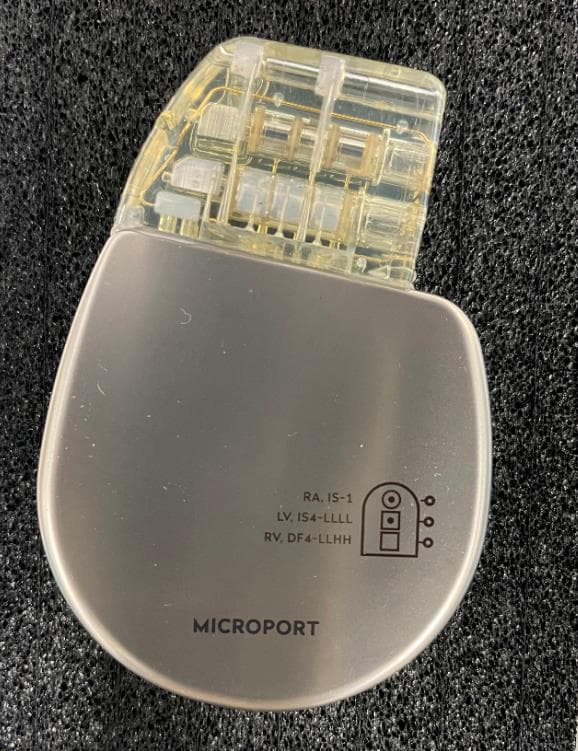
YSGCRTD3744
Jul 16, 2024Defibrillator
Equipment Class
DTS - Digital Transmission System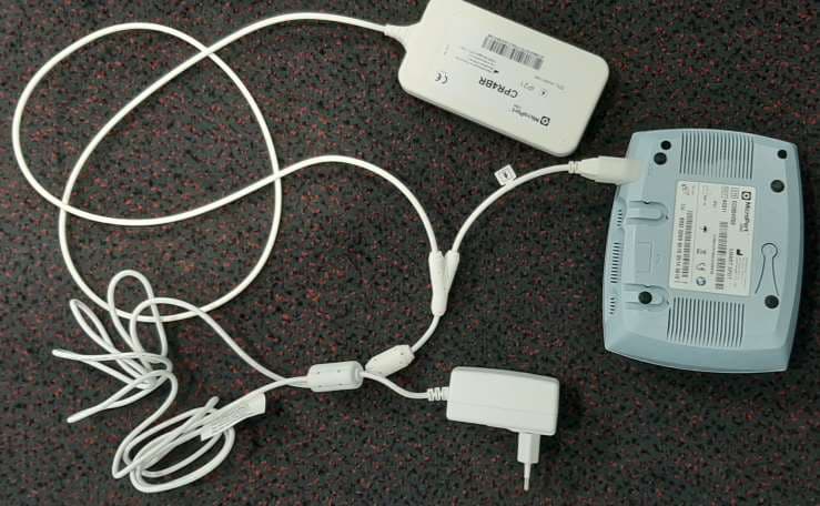
YSGKC861
Oct 08, 2020Smart Spot
Equipment Class
DCD - Part 15 Low Power Transmitter Below 1705 kHz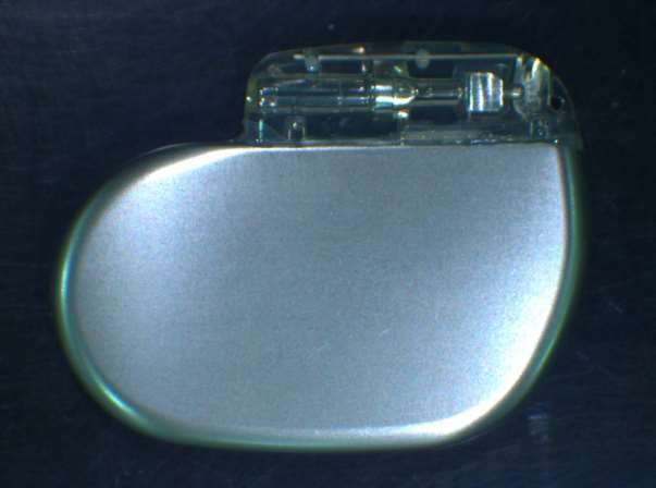
YSG1311
Aug 16, 2020Implantable pacemaker with RF com
Equipment Class
DXX - Part 15 Low Power Communication Device Transmitter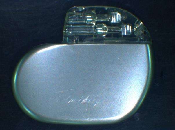
YSG1614
Aug 16, 2020Implantable pacemaker with RF com.
Equipment Class
DXX - Part 15 Low Power Communication Device Transmitter
YSGGB78
Jul 28, 2020Inductive programming head
Equipment Class
DCD - Part 15 Low Power Transmitter Below 1705 kHz