YSH-SC10BSolar Controller
U.S. Sunlight Corporation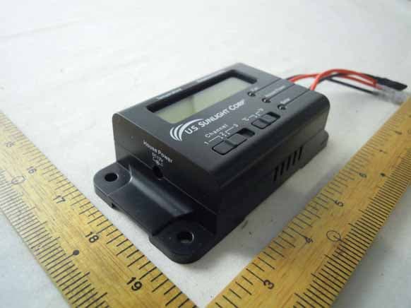
Click to zoom
Application Details
- Equipment Class
- DSC - Part 15 Security/Remote Control Transmitter
- Date of Grant
- Feb 20, 2011
- Application Purpose
- Original Equipment
- Date of Application
- Feb 20, 2011
- Equipment Note
- Solar Controller
- Frequency Range
- 433.92000000 - 433.92000000
- Company
- U.S. Sunlight Corporation
- Country
- United States
Documents & Files
Document Text
Text extracted from the exhibit documents filed with the FCC. Open a document above to read the original.
Users Manual
Table of Contents What is included in this package 1. Tools required2. Installation instructions3. Solar Controller settings and operation4. Tools Required - Philips Screwdriver Pre-Install Check Please read the entirety of the instructions before proceeding with installation. If your Solar Attic Fan has already been installed, please make sure the Solar Fan is working properly before installing the Solar Controller. INSTALLATION TIPS - Before installing the Solar Controller Box in the attic, test and confirm proper communications between Controller Box and Remote by following setup procedures. Installation and Operation Guide Tel: 866-446-0966 www.ussunlight.com [email protected] A2 - 8’ Cables BController Box C Remote Holder D Remote E6 - Mounting Screws FAC Power Adapter G 2 - AAA batteries (not pictured) H 2 - 6” long tie wraps (not pictured) ™ A B C D E F Setting up Solar Controller and the Remote Connect AC Power Adapter to the Controller Box. Temperature and relative humidity 1. will be displayed. The Controller Box has 2 slide switches, the one on the left is for selecting the 2.Radio Frequency (RF) channel and the one on the right is for selecting the temperature readout in Celsius (°C) or Fahrenheit (°F). Align the RF channel (choice of 1,2 and 3) of the Remote with the Controller Box. Both of them must be on the same channel in order to send and receive signals. Select the desired temperature readout unit. (fig 1a & 1b) Remove the back panel of the Remote. Insert 2 AAA batteries (included) in the 3.battery compartment. Replace the back panel of the battery compartment. Test the Remote by pressing the Status button once. This will establish the connection 4. between the Controller Box and Remote. You will hear a “beep” every time the Status button is pressed. This verifies the Remote and Controller Box RF signals are aligned. If there is not a beep, check that the RF channel selector is set to the same channel. If there is still no beep, move both devices to an alternative channel and retry. fig. 1b fig. 1a What is Included in the Box Attic TemperatureAttic humidity Thermo Switch Battery Compartment Fan Mode House Power Solar Power Status Channel Switch Thermo Switch Installing Solar Controller If your Solar Controller came bundled with an attic fan, install the fan first following the instructions included for that model of fan. When the installation of the fan is complete, install Solar Controller. Note that Solar Controller is designed to work with U.S. Sunlight Solar Attic ventilation products.DO NOT ATTEMPT to connect Solar Controller to other solar fans. Copyright 2011 US Sunlight Corp, Inc. REV A 1/2011 ver 1 Installation with use of House Electricity Installing Solar Controller with the AC Power Adapter will provide these additional benefits: 4. Extends fan operation into the evening hours 5. Allows fan to operate when no sun is available 6. Intelligently limits the amount of house electricity to be used for adequate ventilation Standard Installation When implementing the standard installation, Solar Controller will run only on power generated by the solar panel and will provide these functions: Reads attic temperature and relative humidity and dis1.plays them on the Controller Box and Remote Monitors fan and solar panel working conditions2. Allows user to enable or disable Thermo Switch on the 3.Remote (Note: These functions will be active only when the sun is available to generate electricity from the solar panel) Solar Controller can be installed with or without the use of house electricity: Remote Diagram 1. Bring the complete Solar Controller Kit, including the Remote and Controller Box, to the attic. 2.Check and make sure the Thermo Switch on the back of the Remote is set to the OFF position 3. Install the Controller Box on a nearby rafter close to the bottom of the roof with the provided mounting screws.(fig 2a & 2b) The Controller Box has vents on either side of the housing that allow the temperature and humidity sensors to work, so it is important to locate the Controller Box with at least 1 inch of space between it and the underside of the roof. (fig 3 & 4) For best results, locate the Controller Box near the fan opening as shown. Mounting within 2 to 3 feet of the motor is recommended. (fig 5) Standard Installation 4. Unplug the 2 wire leads (red and black) from the motor. (fig 6) If your fan came with a thermal switch, unplug the wire coming in from the solar panel to the switch.(fig 7) The Controller Box will be replacing the function of this switch. You will not need the thermal switch and it can be discarded. fig. 2b fig. 2a fig. 3fig. 4fig. 5 fig. 6 fig. 8fig. 9 fig. 10 fig. 7 6. Take the other 8’ cable and connect the female leads to the solar connectors on the Controller Box (red to red and black to black) and connect the male leads into the female leads coming from the solar panel. (fig 10) 5. Take one 8’ cable (included) and plug the female leads into the motor (red to red and black to black) (fig 8) and connect the male leads to the fan connectors on the Controller Box. (fig 9) Note: It is important to connect the Controller Box to the motor BEFORE connecting to the solar panel. WARNING: Fan will begin running as soon as sun hits the solar panel - keep fingers clear of the fan blades. fig. 14 fig. 16fig. 17fig. 15 Installation with Use of Optional House Electricity To utilize the house electricity option with Solar Controller, connect the Controller Box to an AC outlet with the included AC Power Adapter. You may want to consult an electrician to decide on the best method for your situation. The AC Power Adapter works on a standard 110V outlet. DO NOT USE AN EXTENSION CORD FOR THIS CONNECTION. Complete steps 1~10 in the standard installation.1. Temporarily disconnect wiring to the solar connectors at the Controller Box.2. The AC Power Adapter comes with 4.5 ft. of cord. Verify the power source (outlet) is located 3. within that distance. (fig 13…
Text truncated - open the document above for the full version.
Cover Letter(s)
SCS-F18: Project and Product Certification Representative Authorization Letter Page 1 of 2 Rev 2.0 2206 Ringwood Avenue San Jose, CA 95131 Tel: 408-526-1188 Fax: 408-526-1088 Email: [email protected] Project and Product Certification Representative Authorization Letter Reason for Amendment (current / obsolete) Revision History Approved Date From To Initial Release (current) 1.0 1.0 Nov-14-2006 Revised wording (current) 1.0 2.0 Sept–25-2007
Cover Letter(s)
SCS-F19: Confidentiality Request Letter Page 1 of 2 Rev 2.0 2206 Ringwood Avenue San Jose, CA 95131 Tel: 408-526-1188 Fax: 408-526-1088 Email: [email protected] Confidentiality Request Letter Reason for Amendment (current / obsolete) Revision History Approved Date From To Initial Release (current) 1.0 1.0 Nov-14-2006 Adding CFR 2.459 1.0 2.0 August – 11 - 2008 SCS-F19: Confidentiality Request Letter Page 2 of 2 Rev 2.0 U.S. Sunlight Corporation 5625-B Brisa Street, Livermore, California 94550 U.S.A. (Feb. 10, 2011) To: Federal Communications Commission Authorization and Evaluation Division 7435 Oakland Mills Road Columbia, MD Confidentiality Request regarding application for certification of FCC ID: YSH-SC10B We hereby request confidential treatment of information accompanying this application as outlined below: - Schematics - Block Diagram - Operational Description The above materials contain trade secrets and proprietary information not customarily released to the public. The public disclosure of these materials may be harmful to the applicant and provide unjustified benefits to its competitors. The applicant understands that pursuant to Section 0.457 & 0.459 of the Rules, disclosure of this application and all accompanying documentation will not be made before the date of the Grant for this application. Sincerely, Robert Huang / Director of Engineering Tel: (925) 271-7614 Fax: (925) 605-3981 E-Mail: [email protected] 5625-B Brisa Street, Livermore, California 94550 U.S.A.
External Photos
CERPASS TECHNOLOGY CORP. Report No.: TEII1009025 Cerpass Technology Corp. Issued Date : Dec. 20, 2010 Tel:886-2-2655-8100 Fax:886-2-2655-8200 Page No. : A1 of A4 Appendix A. Photographs of EUT
ID Label/Location Info
Label & Location
Internal Photos
CERPASS TECHNOLOGY CORP. Report No.: TEII1009025 Cerpass Technology Corp. Issued Date : Dec. 20, 2010 Tel:886-2-2655-8100 Fax:886-2-2655-8200 Page No. : A2 of A4 CERPASS TECHNOLOGY CORP. Report No.: TEII1009025 Cerpass Technology Corp. Issued Date : Dec. 20, 2010 Tel:886-2-2655-8100 Fax:886-2-2655-8200 Page No. : A3 of A4 CERPASS TECHNOLOGY CORP. Report No.: TEII1009025 Cerpass Technology Corp. Issued Date : Dec. 20, 2010 Tel:886-2-2655-8100 Fax:886-2-2655-8200 Page No. : A4 of A4
Test Report
CERPASS TECHNOLOGY CORP. Report No.: TEFI1009025 Cerpass Technology Corp. Issued date : Dec. 20, 2010 Tel:886-2-2655-8100 Fax:886-2-2655-8200 Page No. : 1 of 30 FCC TEST REPORT According to FCC Part 15, Subpart C (15.231) / ANSI C63.4: 2003 Applicant : U.S. Sunlight Corporation Address : 5625-B Brisa Street, Livermore, California 94550 U.S.A. Equipment : Solar Controller Model No. : SC10B FCC ID. : YSH-SC10B Trade Name : US Sunlight Laboratory Accreditation The test result refers exclusively to the test presented test model / sample., Without written approval of Cerpass Technology Corp., the test report shall not be reproduced except in full. CERPASS TECHNOLOGY CORP. Report No.: TEFI1009025 Cerpass Technology Corp. Issued date : Dec. 20, 2010 Tel:886-2-2655-8100 Fax:886-2-2655-8200 Page No. : 2 of 30 Contents 1. Report of Measurements and Examinations .................................................................................... 4 1.1 List of Measurements and Examinations ................................................................................... 4 2. Test Configuration of Equipment under Test ................................................................................... 5 2.1 Feature of Equipment under Test ............................................................................................... 5 2.2 Test Mode and Test Software ..................................................................................................... 5 2.3 Description of Test System ......................................................................................................... 5 2.4 Connection Diagram of Test System .......................................................................................... 5 2.5 General Information of Test ........................................................................................................ 6 2.6 Measurement Uncertainty .......................................................................................................... 6 2.7 History of this test report ............................................................................................................ 7 3. Antenna Requirements ....................................................................................................................... 8 3.1 Standard Applicable ................................................................................................................... 8 3.2 Antenna Construction and Directional Gain ............................................................................... 8 4. Test of Conducted Emission .............................................................................................................. 9 4.1 Test Limit .................................................................................................................................... 9 4.2 Test Procedures ......................................................................................................................... 9 4.3 Typical Test Setup .................................................................................................................... 10 4.4 Measurement Equipment ......................................................................................................... 10 4.5 Test Result and Data ................................................................................................................ 11 4.6 Test Photographs ..................................................................................................................... 13 5. Test of Radiated Emission ............................................................................................................... 14 5.1 Test Limit .................................................................................................................................. 14 5.2 Test Procedures ....................................................................................................................... 15 5.3 Duty Cycle ................................................................................................................................ 16 5.4 Typical Test Setup .................................................................................................................... 17 5.5 Measurement Equipment ......................................................................................................... 17 5.6 Test Result and Data ................................................................................................................ 18 5.7 Test Photographs ..................................................................................................................... 26 6. 20dB Occupied Bandwidth Measurement ...................................................................................... 27 6.1 Test Procedure ......................................................................................................................... 27 6.2 Test Setup Layout .................................................................................................................... 27 6.3 Limits of Band Edges Measurement ........................................................................................ 27 6.4 Measurement Equipment ......................................................................................................... 27 6.5 Test Result and Data ................................................................................................................ 27 7. Transmission Time Control .............................................................................................................. 29 7.1 Test Procedure ......................................................................................................................... 29 7.2 Test Setup Layout .................................................................................................................... 29 7.3 Test Limit ....…
Text truncated - open the document above for the full version.
Test Setup Photos
CERPASS TECHNOLOGY CORP. Report No.: TEII1009025 Cerpass Technology Corp. Issued date : Dec. 20, 2010 Tel:886-2-2655-8100 Fax:886-2-2655-8200 Page No. : 13 of 35 4.6 Test Photographs Front View Rear View CERPASS TECHNOLOGY CORP. Report No.: TEII1009025 Cerpass Technology Corp. Issued date : Dec. 20, 2010 Tel:886-2-2655-8100 Fax:886-2-2655-8200 Page No. : 31 of 35 5.6 Test Photographs Front View Rear View
Contact Information
Applicant
Robert Huang(Director of Engineering)
Test Firm
Cerpass Technology CorporationAnson Chou
Technical Specifications
| # | Rule Parts | Frequency Range | Power Output |
|---|---|---|---|
| 1 | 15.231 | 433.92 MHz - 433.92 MHz | - |
Other Applications from U.S. Sunlight Corporation

YSH-SC10R
Feb 20, 2011Solar Controller
Equipment Class
DSC - Part 15 Security/Remote Control Transmitter