YSKXW1Wireless LAN Module
OM Digital Solutions Corporation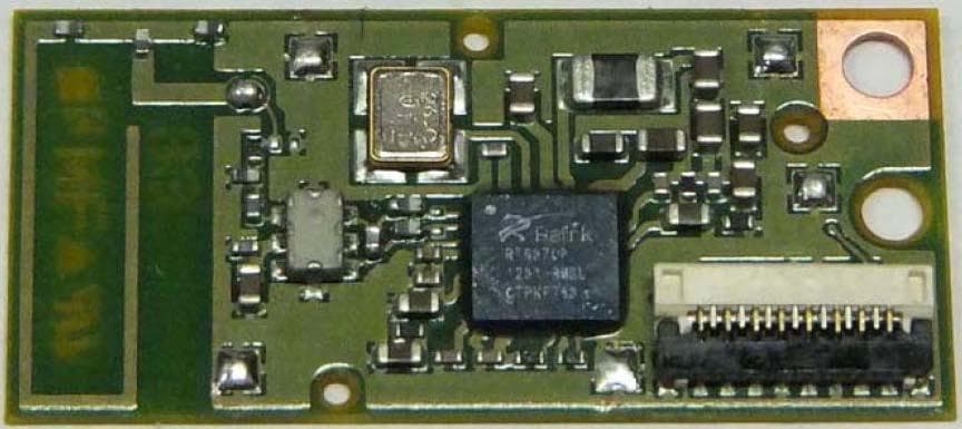
Click to zoom
Application Details
- Equipment Class
- DTS - Digital Transmission System
- Date of Grant
- Feb 04, 2014
- Application Purpose
- Original Equipment
- Date of Application
- Feb 04, 2014
- Equipment Note
- Wireless LAN Module
- Frequency Range
- 2412.00000000 - 2462.00000000
- Country
- Japan
Documents & Files
Document Text
Text extracted from the exhibit documents filed with the FCC. Open a document above to read the original.
Users Manual
User Manual Since this module is not sold to general end users directly, there is no user manual of module. For the details about this module, please refer to the specification sheet of module. This module should be installed in the host device according to the interface specification (installation procedure). The following information must be indicated on the host device of this module; [for FCC] Contains Transmitter Module FCC ID: YSKXW1 or Contains FCC ID: YSKXW1 This device complies with part 15 of the FCC Rules. Operation is subject to the following two conditions: (1) This device may not cause harmful interference, and (2) this device must accept any interference received, including interference that may cause undesired operation. *If it is difficult to describe this statement on the host product due to the size, please describe in the User's manual. [for IC] Contains Transmitter Module IC: 4763E-XW1 or Contains IC: 4763E-XW1 The following statements must be described on the user manual of the host device of this module; [for FCC] FCC CAUTION Changes or modifications not expressly approved by the party responsible for compliance could void the user’s authority to operate the equipment. This transmitter must not be co-located or operated in conjunction with any other antenna or transmitter. For Mobile use This equipment complies with FCC radiation exposure limits set forth for an uncontrolled environment and meets the FCC radio frequency (RF) Exposure Guidelines. This equipment should be installed and operated keeping the radiator at least 20cm or more away from person’s body. For Portable use The available scientific evidence does not show that any health problems are associated with using low power wireless devices. There is no proof, however, that these low power wireless devices are absolutely safe. Low power Wireless devices emit low levels of radio frequency energy (RF) in the microwave range while being used. Whereas high levels of RF can produce health effects (by heating tissue), exposure of low-level RF that does not produce heating effects causes no known adverse health effects. Many studies of low-level RF exposures have not found any biological effects. Some studies have suggested that some biological effects might occur, but such findings have not been confirmed by additional research. [Product (Model)] has been tested and found to comply with FCC radiation exposure limits set forth for an uncontrolled environment and meets the FCC radio frequency (RF) Exposure Guidelines. * Portable device: Distance between the person's body and the antenna is 20cm or less. * Mobile device: Distance between the person's body and the antenna is more than 20cm. [for IC] This device complies with Industry Canada licence-exempt RSS standard(s). Operation is subject to the following two conditions: (1) this device may not cause interference, and (2) this device must accept any interference, including interference that may cause undesired operation of the device. Le présent appareil est conforme aux CNR d'Industrie Canada applicables aux appareils radio exempts de licence. L'exploitation est autorisée aux deux conditions suivantes : (1) l'appareil ne doit pas produire de brouillage, et (2) l'utilisateur de l'appareil doit accepter tout brouillage radioélectrique subi, même si le brouillage est susceptible d'en compromettre le fonctionnement. For Mobile use This equipment complies with IC radiation exposure limits set forth for an uncontrolled environment and meets RSS-102 of the IC radio frequency (RF) Exposure rules. This equipment has very low levels of RF energy that it deemed to comply without maximum permissive exposure evaluation (MPE). Cet équipement est conforme aux limites d’exposition aux rayonnements énoncées pour un environnement non contrôlé et respecte les règles d’exposition aux fréquences radioélectriques (RF) CNR-102 de l’IC. Cet équipement émet une énergie RF très faible qui est considérée conforme sans évaluation de l’exposition maximale autorisée. For Portable use This equipment complies with IC radiation exposure limits set forth for an uncontrolled environment and meets RSS-102 of the IC radio frequency (RF) Exposure rules. This equipment has very low levels of RF energy that are deemed to comply without testing of specific absorption ratio (SAR). Cet équipement est conforme aux limites d’exposition aux rayonnements énoncées pour un environnement non contrôlé et respecte les règles d’exposition aux fréquences radioélectriques (RF) CNR-102 de l’IC. Cet équipement émet une énergie RF très faible qui est considérée conforme sans évaluation du débit d’absorption spécifique (DAS).
External Photos
O-W092 ౮⌀ O-W092 photo Side-A : without case Side-A : with case Side-B
RF Exposure Info
Test report No. : 10184711H Page : 2 of 56 FCC ID : YSKXW1 Issued date : January 29, 2014 UL Japan, Inc. Head Office EMC Lab. 4383-326 Asama-cho, Ise-shi, Mie-ken 516-0021 JAPAN Telephone: +81 596 24 8999 Facsimile: +81 596 24 8124 REVISION HISTORY Original Test Report No.: 10184711H Revision Test report No. Date Page revisedContents - (Original) 10184711H January 29, 2014 - - Test report No. : 10184711H Page : 3 of 56 FCC ID : YSKXW1 Issued date : January 29, 2014 UL Japan, Inc. Head Office EMC Lab. 4383-326 Asama-cho, Ise-shi, Mie-ken 516-0021 JAPAN Telephone: +81 596 24 8999 Facsimile: +81 596 24 8124 CONTENTS PAGE SECTION 1: Customer information ................................................................................................................................................................... 4 SECTION 2: Equipment under test (E.U.T.) ..................................................................................................................................................... 4 2.1 Identification of E.U.T. ...................................................................................................................................... 4 2.2 Product description ............................................................................................................................................. 4 SECTION 3 : Test standard information ........................................................................................................................................................... 6 3.1 Test Specification ............................................................................................................................................... 6 3.2 Procedure ............................................................................................................................................................ 6 3.3 Exposure limit .................................................................................................................................................... 7 3.4 Test Location ...................................................................................................................................................... 7 SECTION 4 : Test result ....................................................................................................................................................................................... 8 4.1 Stand-alone SAR result ...................................................................................................................................... 8 SECTION 5 : Description of the operating mode .............................................................................................................................................. 9 5.1 Output power operating modes ........................................................................................................................... 9 5.2 Output power measurement results .................................................................................................................... 10 5.3 SAR testing operating modes ............................................................................................................................. 13 5.4 Confirmation after SAR testing .......................................................................................................................... 14 SECTION 6 SAR test exclusion considerations ................................................................................................................................................. 15 6.1 Standalone SAR test exclusion considerations ................................................................................................... 15 SECTION 7: Description of the Body setup ....................................................................................................................................................... 16 7.1 Test position for Body setup ............................................................................................................................... 16 SECTION 8 : Test surrounding ........................................................................................................................................................................... 17 8.1 Measurement uncertainty ................................................................................................................................... 17 SECTION 9 : Measurement results ..................................................................................................................................................................... 18 9.1 WLAN Body SAR (2.4G) .................................................................................................................................. 18 SECTION 10 Test instruments ............................................................................................................................................................................ 19 APPENDIX 1 : SAR Measurement data ............................................................................................................................................................. 20 1. Evaluation procedure ................................................................................................................................. 20 2. Measurement data ...................................................................................................................................... 21 APPENDIX2 : System check ................................................................................................................................................................................ 25 1. System check result Body 2450 ................................................................................................................. 25 2. System check Dipole (D2450V2,S/N:713) .........................…
Text truncated - open the document above for the full version.
Test Report
Test report No. : 10184718H-A-R1 Page : 2 of 56 Issued date : January 30, 2014 Revised date : February 5, 2014 FCC ID : YSKXW1 UL JapaUL Japan, Inc. Head Office EMC Lab. 4383-326 Asama-cho, Ise-shi, Mie-ken 516-0021 JAPAN Telephone : +81 596 24 8999 Facsimile : +81 596 24 8124 REVISION HISTORY Original Test Report No.: 10184718H-A Revision Test report No. Date Page revised Contents - (Original) 10184718H-A January 30, 2014 - - 1 10184718H-A-R1 February 5, 2014 P.20 Addition of "(EIRP)" to cell of "Result" in the table. 1 10184718H-A-R1 February 5, 2014 P.20 Addition of "+ Antenna Gain" into calculation formula. Test report No. : 10184718H-A-R1 Page : 3 of 56 Issued date : January 30, 2014 Revised date : February 5, 2014 FCC ID : YSKXW1 UL JapaUL Japan, Inc. Head Office EMC Lab. 4383-326 Asama-cho, Ise-shi, Mie-ken 516-0021 JAPAN Telephone : +81 596 24 8999 Facsimile : +81 596 24 8124 CONTENTS PAGE SECTION 1: Customer information ......................................................................................................... 4 SECTION 2: Equipment under test (E.U.T.) ........................................................................................... 4 SECTION 3: Test specification, procedures & results ............................................................................ 5 SECTION 4: Operation of E.U.T. during testing .................................................................................... 8 SECTION 5: Conducted Emission .......................................................................................................... 10 SECTION 6: Radiated Spurious Emission ............................................................................................ 11 SECTION 7: Antenna Terminal Conducted Tests ................................................................................ 12 APPENDIX 1: Data of EMI test .............................................................................................................. 13 Conducted Emission ......................................................................................................................... 13 6dB Bandwidth ................................................................................................................................. 14 Maximum Peak Output Power .......................................................................................................... 17 Average Output Power ...................................................................................................................... 20 Radiated Spurious Emission ............................................................................................................. 21 Conducted Spurious Emission .......................................................................................................... 28 Conducted Emission Band Edge compliance ................................................................................... 46 Power Density ................................................................................................................................... 47 99% Occupied Bandwidth ................................................................................................................ 51 APPENDIX 2: Test instruments ............................................................................................................. 53 APPENDIX 3: Photographs of test setup ............................................................................................... 54 Conducted Emission ......................................................................................................................... 54 Radiated Spurious Emission ............................................................................................................. 55 Worst Case Position (Horizontal: X-axis/ Vertical:Y-axis) .............................................................. 56 Test report No. : 10184718H-A-R1 Page : 4 of 56 Issued date : January 30, 2014 Revised date : February 5, 2014 FCC ID : YSKXW1 UL JapaUL Japan, Inc. Head Office EMC Lab. 4383-326 Asama-cho, Ise-shi, Mie-ken 516-0021 JAPAN Telephone : +81 596 24 8999 Facsimile : +81 596 24 8124 SECTION 1: Customer information Company Name : OLYMPUS IMAGING CORP. Address : 2951 Ishikawa-machi, Hachioji-shi Tokyo 192-8507, Japan Telephone Number : +81-42-642-5259 Facsimile Number : +81-42-642-2398 Contact Person : Keisuke Hasegawa SECTION 2: Equipment under test (E.U.T.) 2.1 Identification of E.U.T. Type of Equipment : Wireless LAN Module Model No. : O-W092 Serial No. : Refer to Section 4, Clause 4.2 Rating : DC 3.3V Receipt Date of Sample : September 17, 2012 Country of Mass-production : Philippines Condition of EUT : Production prototype (Not for Sale: This sample is equivalent to mass-produced items.) Modification of EUT : No Modification by the test lab 2.2 Product Description General Specification Clock frequency(ies) in the system : 26MHz Radio Specification of WLAN (IEEE802.11b/g/n) Radio Type : Transceiver Frequency of Operation : 2412-2462MHz Modulation : DSSS and OFDM Power Supply (radio part input) : DC3.3V (Digital part), DC1.6V (RF Core), DC1.2V (Digital part) Antenna type : 2.4GHz Pattern Antenna Antenna Gain : 0.41dBi Test report No. : 10184718H-A-R1 Page : 5 of 56 Issued date : January 30, 2014 Revised date : February 5, 2014 FCC ID : YSKXW1 UL JapaUL Japan, Inc. Head Office EMC Lab. 4383-326 Asama-cho, Ise-shi, Mie-ken 516-0021 JAPAN Telephone : +81 596 24 8999 Facsimile : +81 596 24 8124 SECTION 3: Test specification, procedures & results 3.1 Test Specification Test Specification : FCC Part 15 Subpart C: 2013, final revised on September 30, 2013 and effective October 30, 2013 Title : FCC 47CFR Part15 Radio Frequency Device Subpart C Intentional Radiators Section 15.207 Conducted limits Section 15.247 Operation within the bands 902-928MHz, 2400-2483.5MHz, and 5725-5850MHz * The revision on September 30, 2013 does not affec…
Text truncated - open the document above for the full version.
Test Setup Photos
Test report No. : 10184711H Page : 53 of 56 FCC ID : YSKXW1 Issued date : January 29, 2014 UL Japan, Inc. Head Office EMC Lab. 4383-326 Asama-cho, Ise-shi, Mie-ken 516-0021 JAPAN Telephone: +81 596 24 8999 Facsimile: +81 596 24 8124 Fron t Rear Top Left Side Bottom Right Side APPENDIX 4: Photographs of test setup 1. Photographs of EUT Test report No. : 10184711H Page : 54 of 56 FCC ID : YSKXW1 Issued date : January 29, 2014 UL Japan, Inc. Head Office EMC Lab. 4383-326 Asama-cho, Ise-shi, Mie-ken 516-0021 JAPAN Telephone: +81 596 24 8999 Facsimile: +81 596 24 8124 2. Antenna position Antenna 4.526 9.05 49.875 29.865 Antenna Shortest distance 3.3911 5.23 98.86 Antenna Unit: mm Test report No. : 10184711H Page : 55 of 56 FCC ID : YSKXW1 Issued date : January 29, 2014 UL Japan, Inc. Head Office EMC Lab. 4383-326 Asama-cho, Ise-shi, Mie-ken 516-0021 JAPAN Telephone: +81 596 24 8999 Facsimile: +81 596 24 8124 3. Photographs of setup Front(Lens) Test report No. : 10184711H Page : 56 of 56 FCC ID : YSKXW1 Issued date : January 29, 2014 UL Japan, Inc. Head Office EMC Lab. 4383-326 Asama-cho, Ise-shi, Mie-ken 516-0021 JAPAN Telephone: +81 596 24 8999 Facsimile: +81 596 24 8124 Right side End of Report
Test Setup Photos
Test report No. : 10184718H-A-R1 Page : 54 of 56 Issued date : January 30, 2014 Revised date : February 5, 2014 FCC ID : YSKXW1 UL JapaUL Japan, Inc. Head Office EMC Lab. 4383-326 Asama-cho, Ise-shi, Mie-ken 516-0021 JAPAN Telephone : +81 596 24 8999 Facsimile : +81 596 24 8124 APPENDIX 3: Photographs of test setup Conducted Emission Photo 1 Photo 2 Test report No. : 10184718H-A-R1 Page : 55 of 56 Issued date : January 30, 2014 Revised date : February 5, 2014 FCC ID : YSKXW1 UL JapaUL Japan, Inc. Head Office EMC Lab. 4383-326 Asama-cho, Ise-shi, Mie-ken 516-0021 JAPAN Telephone : +81 596 24 8999 Facsimile : +81 596 24 8124 Radiated Spurious Emission Photo 1 Photo 2 Test report No. : 10184718H-A-R1 Page : 56 of 56 Issued date : January 30, 2014 Revised date : February 5, 2014 FCC ID : YSKXW1 UL JapaUL Japan, Inc. Head Office EMC Lab. 4383-326 Asama-cho, Ise-shi, Mie-ken 516-0021 JAPAN Telephone : +81 596 24 8999 Facsimile : +81 596 24 8124 Worst Case Position (Horizontal: X-axis/ Vertical:Y-axis) X-axis Y-axis Z-axis End of Report
Contact Information
Applicant
Takehito Higashi(Executive Director)
Technical Contact
UL Japan, Inc.Masanori Nishiyama
[email protected]81-596-24-8999
4383-326 Asama-cho, Ise-shi · Mie-ken · Japan
Test Firm
UL Japan, Inc. Head office EMC Lab.Tetsuya Hashimoto
Technical Specifications
| # | Rule Parts | Frequency Range | Power Output |
|---|---|---|---|
| 1 | 15C | 2.41 GHz - 2.46 GHz | 91.00 mW |
Other Applications from OM Digital Solutions Corporation
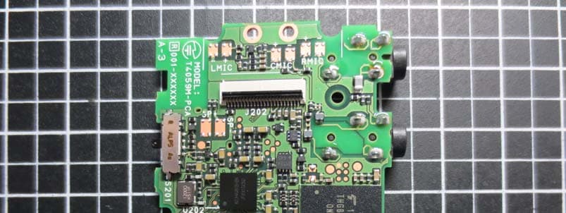
YSKA02
Aug 26, 2015The Module for Linear PCM Recorder
Equipment Class
DSS - Part 15 Spread Spectrum Transmitter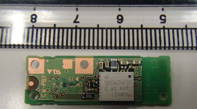
YSKW59
Apr 01, 2015Wireless LAN Module
Equipment Class
DTS - Digital Transmission System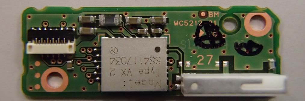
YSKW55
Dec 16, 2014Wireless LAN Module
Equipment Class
DTS - Digital Transmission System
YSKPP1
Oct 25, 2010Communication Unit
Equipment Class
DSS - Part 15 Spread Spectrum Transmitter