YTESM03Hearing System
Sonitus Medical Inc.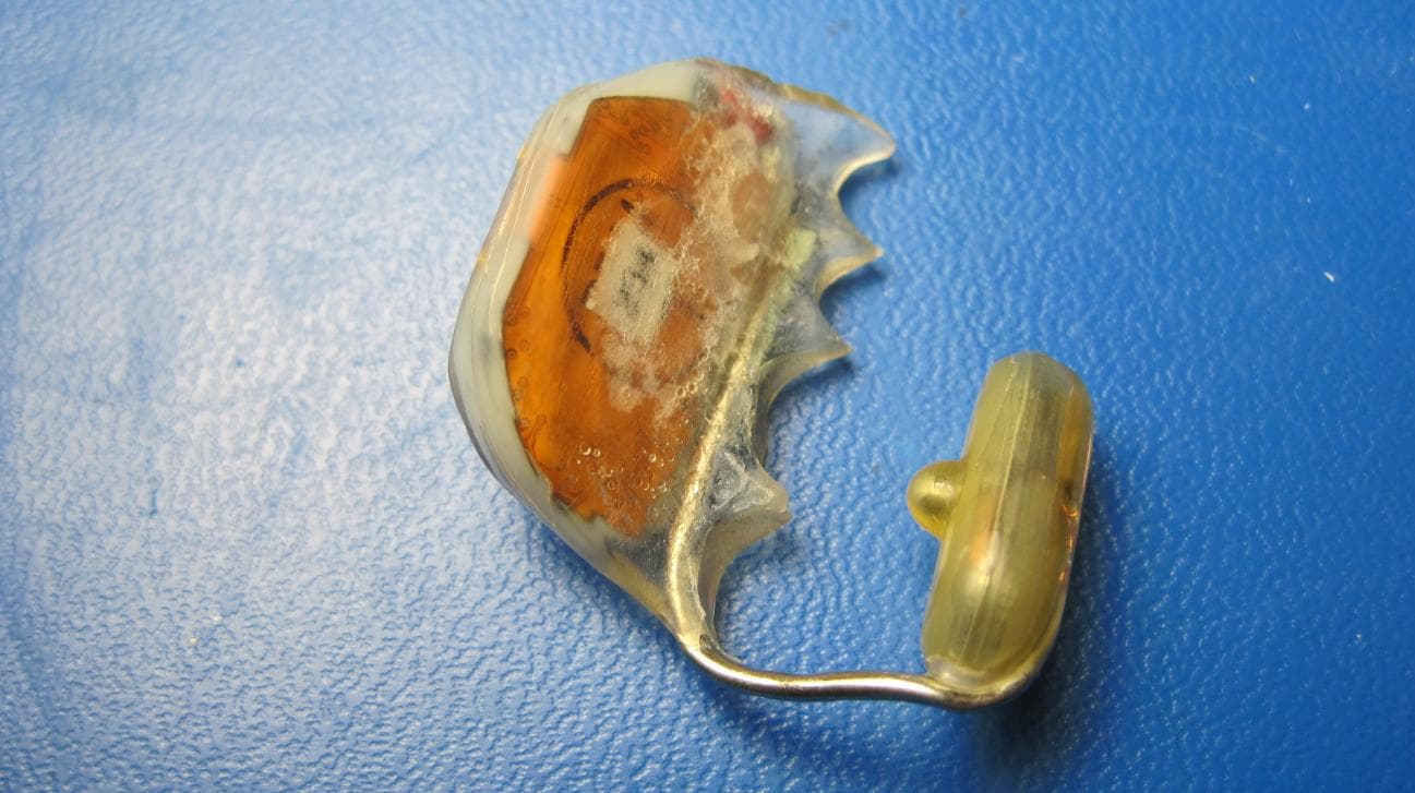
Click to zoom
Application Details
- Equipment Class
- DXT - Part 15 Low Power Transceiver, Rx Verified
- Date of Grant
- Feb 16, 2011
- Application Purpose
- Original Equipment
- Date of Application
- Feb 16, 2011
- Equipment Note
- Hearing System
- Frequency Range
- 10.60000000 - 10.60000000
- Company
- Sonitus Medical Inc.
- Country
- United States
Documents & Files
Document Text
Text extracted from the exhibit documents filed with the FCC. Open a document above to read the original.
Users Manual
1 Patient Instructions for Use (IFU) & Information Guide For the SoundBite™ Hearing System by Sonitus Medical MP-11-0002 Rev 1.doc Nov 7, 2010 2 User Assistance information For information regarding the proper use of the SoundBite Hearing System, contact the prescribing physician. Caution: Federal law restricts this device to sale by or on the order of a licensed healthcare practitioner. SoundBite Hearing System Components: 1. SoundBite™ In-the-Mouth ―ITM‖ hearing devices (2) 2. Behind the Ear ―BTE‖ microphone unit (1) 3. Carrying Cases (2: One for the ITMs and one for the BTE) 4. System Charger (2) 3 Warnings Keep the SoundBite Hearing system components away from strong magnetic fields. The ITM and BTE must be removed prior to undergoing an MRI exam. If the ITM is swallowed, seek emergency assistance immediately and ask the emergency professional to contact your treatment provider for information regarding the SoundBite ITM device. Do not consume alcohol while wearing the device or wear the device while under the influence of alcohol or drugs, as it could decrease your normal gagging reflex and increase the possibility of swallowing the ITM device. If you experience persistent soreness or inflammation in your mouth or behind/in your ear please contact your treatment provider. Under certain conditions, the SoundBite ITM and BTE units may heat up to a temperature of 44.1C. If the units become unusually warm while wearing them, you should remove them immediately, discontinue use and contact your treatment provider. Do not play sports while wearing the device as athletic or physical contact may damage your teeth. Assure that the ITM is dry before placing it in the charger. All components should be kept out of the reach of children, pets, or anyone who might swallow them or otherwise be at risk of being harmed by the device. If any component is swallowed, seek emergency attention from a medical provider immediately. Do not allow others to wear or use either component to avoid damage to your device and potential harm to others. The SoundBite system needs special precautions regarding EMC and needs to be installed and put into service according to the EMC information provided in this manual. Portable and mobile RF (radio frequency) communications equipment may affect the performance of your BTE (behind-the-ear) and ITM (in-the-mouth) devices. The SoundBite system should not be used adjacent to or stacked with other equipment. If adjacent or stacked used is necessary, the SoundBite System should be observed to verify normal operation in the configuration in which it will be used. Do not disassemble the BTE or ITM, expose to heat above 140F (60C) or dispose of by incineration. 4 Precautions Protect the BTE microphone unit from excessive moisture as this may damage the device. Remove the unit before showering, bathing, or swimming. Dropping risk of damage – do not drop the device as this may cause damage. Take care to properly handle the device, as incorrect handling or dropping the device(s) may cause malfunction and/or permanent damage to the components. Protect the devices from excessive heat as this may cause damage; do not leave near windows or in a car. If you have a history of recurrent dizziness and these symptoms are present while wearing the device, you should discontinue use of the device and consult with your treating physician. Although it will most likely not cause damage to the device, X-Ray type radiation including CT scans or airport security terminals may temporarily cause the device to improperly perform. It is recommended that all components are removed prior to any such scanning procedure. Modifications or changes to all components are not allowed by any party other than those appointed and approved by Sonitus Medical, Inc. If any component of your system fails to operate or if it is damaged, contact your treatment provider. The following precautions should be noted if the ITM is worn while eating: o Start slowly by eating softer foods. Consider chewing on the opposite side of your mouth from where the ITM device is placed. o Some foods may be difficult to eat because they are too sticky or hard to chew while wearing your device. o Certain sticky foods and chewing gum may adversely affect the ability to clean the ITM device and its function. o Food and beverages will not harm the device. But be sure to clean it thoroughly after each time you eat for optimal performance and to maintain oral hygiene. Use only the battery charger and AC wall adapter provided. Other chargers may look similar but may cause damage to your SoundBite device. Never use household cleaning products such as detergents, bleach, etc. to clean your devices as these agents may cause damage to the device 5 User’s Manual for the SoundBite Hearing System 6 System Description The SoundBite Hearing System is a non-surgical and removable bone conduction hearing device designed to imperceptibly transmit sound via the teeth. The SoundBite system consists of: A small BTE (behind the ear) microphone unit worn on the poorer ear Two (2) easy to insert and remove ITM (in the mouth) hearing devices A system charger provided to recharge the batteries in the BTE and ITM. The system charger consists of a standard power outlet AC wall adapter that has docks to simultaneously recharge two ITM hearing devices and the BTE microphone unit. 7 BTE (Behind the Ear) Microphone Unit The BTE microphone unit is pictured below. It has an open fit dome containing the primary microphone, which is placed in the canal of the poorer ear. The dome is connected to the BTE by a discreet translucent tube. This design allows the patient to take advantage of the natural acoustic benefits provided by shape of his or her own ear. The BTE uses a digital signal processor to process the sound and a wireless chip to transmit the signals to the hearing device worn in the mouth. The BTE device is designed to be used on the poor…
Text truncated - open the document above for the full version.
External Photos
FCC Certification – External Photos, SoundBite System Page 1 of 9 11/12/10 Date: 11/12/10 Subject: FCC Certification – External Photos, SoundBite System The SoundBite System is comprised of the BTE (behind-the-ear unit), the OA (oral appliance unit, also known as ITM) and charger system. External photographs of the SoundBite System are shown below. FCC Certification – External Photos, SoundBite System Page 2 of 9 11/12/10 Figure 1. BTE with microphone assy, left side FCC Certification – External Photos, SoundBite System Page 3 of 9 11/12/10 Figure 2. BTE with microphone assy, right side FCC Certification – External Photos, SoundBite System Page 4 of 9 11/12/10 Figure 3. BTE with microphone assy, top FCC Certification – External Photos, SoundBite System Page 5 of 9 11/12/10 Figure 4. BTE with microphone assy, bottom FCC Certification – External Photos, SoundBite System Page 6 of 9 11/12/10 Figure 5. Oral appliance, from lingual side FCC Certification – External Photos, SoundBite System Page 7 of 9 11/12/10 Figure 6. Oral appliance, from buccal side FCC Certification – External Photos, SoundBite System Page 8 of 9 11/12/10 Figure 7. Oral appliance, palate side FCC Certification – External Photos, SoundBite System Page 9 of 9 11/12/10 Figure 8. Charger system
ID Label/Location Info
FCC ID YTESM03 Sonitus Medical 1.0 mm 12.5 mm 3.0 mm Date: 11/12/10 FCC ID Label, SoundBite System
ID Label/Location Info
FCC Label Location, SoundBite System Date: 11/12/10
Test Report
EMC Report for Sonitus Medical on the SoundBite File: 3197926MPK-003 Page 1 of 25 TEST REPORT Report Number: 3197926MPK-003 Project Number: 3197926 November 10, 2010 Testing performed on the Hearing System Model Number: SoundBite FCC ID: YTESM03 to FCC Part 15.209 and RSS-210 Issue 7 for Sonitus Medical, Inc. Test Performed by: Test Authorized by: Intertek 1365 Adams Court Menlo Park, CA 94025 USA Sonitus Medical, Inc. 1825 S. Grant St, Suite 350 San Mateo, CA 94402, USA Prepared by: Date: November 10, 2010 Martin Liu Reviewed by: Date: November 10, 2010 Ollie Moyrong This report is for the exclusive use of Intertek's Client and is provided pursuant to the agreement between Intertek and its Client. Intertek's responsibility and liability are limited to the terms and conditions of the agreement. Intertek assumes no liability to any party, other than to the Client in accordance with the agreement, for any loss, expense or damage occasioned by the use of this report. Only the Client is authorized to copy or distribute this report and then only in its entirety. Any use of the Intertek name or one of its marks for the sale or advertisement of the tested material, product or service must first be approved in writing by Intertek. The observations and test results in this report are relevant only to the sample tested. This report by itself does not imply that the material, product, or service is or has ever been under an Intertek certification program. This report must not be used to claim product endorsement by A2LA, NIST nor any other agency of the U.S. Government. EMC Report for Sonitus Medical on the SoundBite File: 3197926MPK-003 Page 2 of 25 TABLE OF CONTENTS 1.0 Summary of Tests .......................................................................................................................... 3 2.0 General Description ....................................................................................................................... 4 2.1 Product Description............................................................................................................. 4 2.2 Related Submittal(s) Grants ................................................................................................ 5 2.3 Test Methodology ............................................................................................................... 5 2.4 Test Facility......................................................................................................................... 5 3.0 System Test Configuration ............................................................................................................ 6 3.1 Support Equipment and Description ................................................................................... 6 3.2 Block Diagram of Test Setup .............................................................................................. 6 3.3 Justification ......................................................................................................................... 8 3.4 Software Exercise Program ................................................................................................. 8 3.5 Mode of operation during test ............................................................................................. 8 3.6 Modifications required for Compliance .............................................................................. 8 3.7 Additions, deviations and exclusions from standards.......................................................... 8 4.0 Measurement Results..................................................................................................................... 9 4.1 Transmitter Radiated Emissions.......................................................................................... 9 4.2 AC Line Conducted Emission........................................................................................... 18 4.3 Occupied Bandwidth......................................................................................................... 22 5.0 List of Test Equipment ................................................................................................................ 24 6.0 Document History ........................................................................................................................ 25 EMC Report for Sonitus Medical on the SoundBite File: 3197926MPK-003 Page 3 of 25 1.0 Summary of Tests TEST REFERENCE FCC REFERENCE RSS-210 RESULTS Field Strength of Fundamental and Spurious Emissions 15.209 A2.6 Complies Line Conducted Emissions 15.207 RSS-GEN Complies Antenna requirement 15.203 Complies. The antenna is permanently connected, internal to EUT. Occupied Bandwidth Complies EMC Report for Sonitus Medical on the SoundBite File: 3197926MPK-003 Page 4 of 25 2.0 General Description 2.1 Product Description Overview of the EUT Applicant name & address Sonitus Medical, Inc. 1825 S. Grant St, Suite 350 San Mateo, CA 94402, USA Contact info Mr. Sam Mostafavi, [email protected] Model No. SoundBite FCC Identifier YTESM03 Operating Frequency Single frequency, 10.6 MHz Number of Channels 1 Type of Modulation CPFSK Antenna Type Internal Antenna EUT receive date: August 23, 2010 EUT receive condition: The EUT was received in good condition with no apparent damage. Test start date: August 25, 2010 Test completion date: November 8, 2010 Sonitus Medical, Inc. supplied the following description of the EUT: The Sonitus Medical hearing system is designed to detect sound in the audio range via an externally placed microphone, transmit the signal wirelessly to an intra-oral unit in contact with the teeth and reproduce the audio signal which propagates to the cochlea via bone conduction. The system is comprised of the following sub-systems. 1) Behind the Ear (BTE) Device Unit worn behind the ear incorporating a microphone placed within the ear canal. The BTE module wirelessly communicates with the In The Mout…
Text truncated - open the document above for the full version.
Test Setup Photos
Test Setup Photos YTESM03
Contact Information
Applicant
Keri Ng(Director, Regulatory and Quality)
Technical Contact
Intertek Testing Services NA, Inc.Krishna Vemuri
[email protected]650-463-4644
1365 Adams Ct. · Menlo Park, California · United States
Non-Technical Contact
Intertek Testing Services NA, Inc.Krishna Vemuri
[email protected]650-463-4644
Test Firm
Intertek Testing Services NA Inc.John Quigley
Technical Specifications
| # | Rule Parts | Frequency Range | Power Output |
|---|---|---|---|
| 1 | 15C | 10.6 MHz - 10.6 MHz | - |