YTXHA1HEADPHONE AMPLIFIER
OPPO Digital, Inc.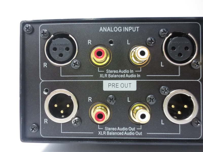
Click to zoom
Application Details
- Equipment Class
- DSS - Part 15 Spread Spectrum Transmitter
- Date of Grant
- Apr 03, 2014
- Application Purpose
- Original Equipment
- Date of Application
- Apr 03, 2014
- Equipment Note
- HEADPHONE AMPLIFIER
- Frequency Range
- 2402.00000000 - 2480.00000000
- Company
- OPPO Digital, Inc.
- Country
- United States
Documents & Files
Document Text
Text extracted from the exhibit documents filed with the FCC. Open a document above to read the original.
Users Manual
HEADPHONE AMPLIFIER HA-1 USER MANUAL USB Made for i Table of Contents Important Information ........................................................................................................................................................ 1 Precautions ................................................................................................................................................................... 2 FCC Statement (For U.S. Customers) .......................................................................................................................... 2 Canada Statement (For Canadian Customers) ............................................................................................................ 2 Legal Notice .................................................................................................................................................................. 3 Compatible iPod/iPhone/iPad Models .......................................................................................................................... 3 Introduction ........................................................................................................................................................................ 4 Accessories .................................................................................................................................................................. 4 Installation ......................................................................................................................................................................... 5 Front Panel Controls ..................................................................................................................................................... 5 Back Panel Connectors ................................................................................................................................................ 5 Remote Control ............................................................................................................................................................ 6 Remote Control Buttons .......................................................................................................................................... 6 Battery Installation ................................................................................................................................................... 6 Using the Remote Control ....................................................................................................................................... 7 Headphone Output Connection .................................................................................................................................... 8 Using the HA-1 as a Pre-Amplifier or DAC ................................................................................................................... 9 RCA Stereo Audio Outputs ...................................................................................................................................... 9 XLR Balanced Audio Outputs .................................................................................................................................. 9 Triggers ................................................................................................................................................................... 9 Input Signal Connections ............................................................................................................................................ 10 RCA Stereo Audio Inputs ...................................................................................................................................... 10 XLR Balanced Audio Inputs ................................................................................................................................... 10 Coaxial Digital Audio Input .................................................................................................................................... 11 Optical Digital Audio Input ..................................................................................................................................... 11 AES / EBU Digital Audio Input ............................................................................................................................... 11 USB (Type B) Audio Input ..................................................................................................................................... 12 Mobile USB Audio Input ........................................................................................................................................ 12 Bluetooth Audio Connection .................................................................................................................................. 13 Bluetooth Setup ..................................................................................................................................................... 13 Using the OPPO HA-1 ..................................................................................................................................................... 14 Basic Operations ........................................................................................................................................................ 14 Power On / Off ....................................................................................................................................................... 14 The Front Panel Display ........................................................................................................................................ 14 ii Source Selection .................................................................................................................................................... 15 Volume Control .........................................…
Text truncated - open the document above for the full version.
Users Manual
12 Note: The Coaxial, Optical and AES/EBU Digital Audio Inputs accept stereo PCM signals only. Compressed audio signals such as Dolby Digital or DTS are not supported. USB (Type B) Audio Input You can connect your computer directly to the HA-1 using a USB-A to USB-B cable. This will allow your computer to function as the digital source, and you will be able to use whatever playback software you prefer to output audio through the HA-1. The digital signal will be converted by the internal DAC and sent to the headphone and line level outputs. This input source is labeled USB DAC on the Source Selection screen and USB on the remote control. Note: Depending on the operating system and playback software used, driver software, specific software settings and configurations may be required in order to enable the computer to play audio into the HA-1. Please visit the HA-1 Support page on the OPPO web site (www.oppodigital.com) for driver download and additional help guides. Mobile USB Audio Input You can connect a compatible iPod, iPhone, or iPad into the Mobile USB Audio Input port on the front panel of the HA-1. A 30-pin dock connector to USB cable or a Lightning™ to USB cable that comes with your Apple product is required for this connection. The digital audio signal from your Apple product will be converted by the internal DAC and sent to the headphone and line level outputs. This input source is labeled MOBILE on both the Source Selection screen and the remote control. Note: USB works with iPhone 5S, iPhone 5C, iPhone 5, iPhone 4S, iPad (4th generation), iPad mini, iPod touch (5th generation). (Type A Male) USB 2.0 Cable (Type B Male) USB Port 110-120V~ / 220-240V~ AES/EBU Coaxial Optical USB DAC R L AC IN R L R LR L RR BBaallaanncceedd AAuudd SStteerreeoo AAuuddiioo IInn XXLLiioo IInn Stereo Audio Out XLR Balanced Audio Out Out ANALOG INPUT DIGITAL INPUT HA-1 HEADPHONE AMPLIFIER In TRIGGER PRE OUT Source Volume HEADPHONE AM PLIFIER HA-1 USB 13 Bluetooth Audio Connection You can connect a Bluetooth-capable mobile device such as a smartphone or digital audio player by enabling Bluetooth on your mobile device and searching for and connecting to the OPPO HA-1. Once successfully paired and connected, the Bluetooth digital audio signal will be converted by the internal DAC and sent to the headphone and line level outputs. This input source is labeled BLUETOOTH on the Source Selection screen and BT on the remote control. Notes: Bluetooth technology works with iPhone 5S, iPhone 5C, iPhone 5, iPhone 4S, iPad (4th generation), iPad mini, and iPod touch (5th generation). Bluetooth technology also works with any mobile device or computer that supports the Bluetooth A2DP profile. Bluetooth Setup When the BLUETOOTH input source is selected, the front panel screen displays the Bluetooth connection status. If a device has not yet been paired, or a previously paired device is not in range, the screen will display Not Connected. If this is the case, you will need to enable Bluetooth on your mobile device, search for the OPPO HA-1, and attempt to pair with it. After pairing successfully, the HA-1 will display that it is Connected. Once you have paired a Bluetooth device, the HA-1 will attempt to reconnect to it when the device is in range and the BLUETOOTH input has been selected on the HA-1. If a new device needs to be paired, but the HA-1 is already connected to a device, you will need to disconnect that device in order to pair the new device. This can be done by un- pairing the HA-1 from the existing device’s Bluetooth menu or by temporarily turning off Bluetooth on the existing device. If the pairing process fails, the HA-1’s Bluetooth status will continue to show Not Connected. If that is the case, you will need to attempt the pairing process again. Source Volume Balanced HEADPHONE AMPLIFIER HA-1 USB 14 Using the OPPO HA-1 Basic Operations Power On / Off When the HA-1 is initially connected to AC power, it stays in standby mode. Pressing the Power Button on the HA-1 will result in the Power Status Indicator turning blue, indicating the HA-1 has powered on. When the unit is powering on, the OPPO logo will appear on the screen. When it is fully ready, one of the pre-selected Home Screens (Status, Spectrum or VU Meter) will appear. Once the HA-1 has powered on, pressing the Power Button again will turn the unit off, at which time the Power Status Indicator will turn off, indicating that it is in standby mode. Remote: The POWER button on the remote control functions in the same way as the Power Button on the front panel of the HA-1. The Front Panel Display When the HA-1 is in its normal operational mode, it shows one of the pre-selected Status, Spectrum or VU Meter screen on its Front Panel Display. This is called the Home Screen Selection. When there is any user operation, the Front Panel Display changes accordingly. Please use it as the visual aid for all operations. Source Volume Balanced HEADPHONE AMPLIFIER HA-1 iPod/iPhone/iPad USB 15 Source Selection The active input source can be selected by rotating the Source Selector Knob. The Front Panel Display will show a Source Selection screen, with the active input source highlighted. When the Source Selector Knob is rotated in either direction, a new input source is highlighted. Once you settle down on an input source by leaving the highlight cursor on it or by pressing the Source Selector Knob, the new input source becomes active and the Front Panel Display returns to the Home Screen. Remote: You can also switch input sources by directly pressing the appropriate source button on the remote. Volume Control Rotating the Volume Knob clockwise or counter-clockwise will increase or decrease the volume level. The Volume screen will appear to provide a visual reference for the volume level. The HA-1 implements its volume control with a pure analog signal path. The numeric dB value displayed on the screen is based on the measurement of the Volume Knob posi…
Text truncated - open the document above for the full version.
External Photos
Neutron Engineering Inc. Project No.: 1312C013 Page 2 of 17 Neutron Engineering Inc. Project No.: 1312C013 Page 3 of 17 Neutron Engineering Inc. Project No.: 1312C013 Page 4 of 17
External Photos
Bluegiga Technologies Sinikalliontie 5A, P.O. Box 120 02630 Espoo FINLAND Tel +358 9 435 5060 | Fax +358 9 435 50660 Co ID 0934238-1, VAT registered, domicile: Espoo www.bluegiga.com | [email protected] WT32-E WT32-A Bluegiga Technologies Sinikalliontie 5A, P.O. Box 120 02630 Espoo FINLAND Tel +358 9 435 5060 | Fax +358 9 435 50660 Co ID 0934238-1, VAT registered, domicile: Espoo www.bluegiga.com | [email protected] WT32-A/E Bottom
ID Label/Location Info
This device complies with Part 15 of the FCC Rules. Operation is subject to the following two conditions: (1) this device may not cause harmful interference, and (2) this device must accept any interference received, including interference that may cause undesired operation.
Internal Photos
Neutron Engineering Inc. Project No.: 1312C013 Page 5 of 17 Neutron Engineering Inc. Project No.: 1312C013 Page 6 of 17 Neutron Engineering Inc. Project No.: 1312C013 Page 7 of 17 Neutron Engineering Inc. Project No.: 1312C013 Page 8 of 17 Neutron Engineering Inc. Project No.: 1312C013 Page 9 of 17 Neutron Engineering Inc. Project No.: 1312C013 Page 10 of 17 Neutron Engineering Inc. Project No.: 1312C013 Page 11 of 17 Neutron Engineering Inc. Project No.: 1312C013 Page 12 of 17 Neutron Engineering Inc. Project No.: 1312C013 Page 13 of 17 Neutron Engineering Inc. Project No.: 1312C013 Page 14 of 17 Neutron Engineering Inc. Project No.: 1312C013 Page 15 of 17 Neutron Engineering Inc. Project No.: 1312C013 Page 16 of 17 Neutron Engineering Inc. Project No.: 1312C013 Page 17 of 17
Internal Photos
Bluegiga Technologies Sinikalliontie 5A, P.O. Box 120 02630 Espoo FINLAND Tel +358 9 435 5060 | Fax +358 9 435 50660 Co ID 0934238-1, VAT registered, domicile: Espoo www.bluegiga.com | [email protected] WT32-E WT32-A
Test Report
Neutron Engineering Inc. Report No.: NEI-FICP-1-1312C013 Page 1 of 94 FCC&IC Radio Test Report FCC ID: YTXHA1 IC: 9323A-HA1 This report concerns (check one): Original Grant Class II Change Issued Date : Jan. 14, 2014 Project No. : 1312C013 Equipment : HEADPHONE AMPLIFIER Model Name : HA-1 Applicant : OPPO Digital ,Inc Address : 2629 Terminal Blvd Suite B Mountain View, CA 94043 Tested by: Neutron Engineering Inc. EMC Laboratory Date of Receipt: Dec. 02, 2013 Date of Test: Dec. 02, 2013~ Jan. 13, 2014 Testing Engineer : (David Mao) Technical Manager : (Leo Hung) Authorized Signatory: (Steven Lu) Neutron Engineering Inc. No.3,Jinshagang 1st Road, ShiXia, Dalang Town, Dong Guan, China. TEL: 0769-8318-3000 FAX: 0769-8319-6000 Neutron Engineering Inc. Report No.: NEI-FICP-1-1312C013 Page 2 of 94 Declaration Neutron represents to the client that testing is done in accordance with standard procedures as applicable and that test instruments used has been calibrated with the standards traceable to National Measurement Laboratory (NML) of CHINA, or National Institute of Standards and Technology (NIST) of U.S.A. Neutron's reports apply only to the specific samples tested under conditions. It is manufacture’s responsibility to ensure that additional production units of this model are manufactured with the identical electrical and mechanical components. Neutron shall have no liability for any declarations, inferences o r generalizations drawn by the client or others from Neutron issued reports. Neutron’s reports must not be used by the client to claim product endorsement by the authorities or any agency of the Government. This report is the confidential property of the client. As a mutual protection to the clients, the public and Neutron-self, extracts from the test report shall not be reproduced except in full with Neutron’s authorized written approval. Neutron’s laboratory quality assurance procedures are in compliance with the ISO Guide 17025 requirements, and accredited by the conformity assessment authorities listed in this test report. Limitation For the use of the authority's logo is limited unless the Test Standard(s)/Scope(s)/Item(s) mentioned in this test report is (are) included in the conformity assessment authorities acceptance respective. Neutron Engineering Inc. Report No.: NEI-FICP-1-1312C013 Page 3 of 94 Table of Contents Page 1 . CERTIFICATION 7 2 . SUMMARY OF TEST RESULTS 8 2.1 TEST FACILITY 9 2.2 MEASUREMENT UNCERTAINTY 9 3 . GENERAL INFORMATION 10 3.1 GENERAL DESCRIPTION OF EUT 10 3.2 DESCRIPTION OF TEST MODES 12 3.3 TABLE OF PARAMETERS OF TEXT SOFTWARE SETTING 12 3.4 BLOCK DIAGRAM SHOWING THE CONFIGURATION OF SYSTEM TESTED 13 3.5 DESCRIPTION OF SUPPORT UNITS 14 4 . EMC EMISSION TEST 15 4.1 CONDUCTED EMISSION MEASUREMENT 15 4.1.1 POWER LINE CONDUCTED EMISSION LIMITS 15 4.1.2 TEST PROCEDURE 15 4.1.3 DEVIATION FROM TEST STANDARD 15 4.1.4 TEST SETUP 16 4.1.5 EUT OPERATING CONDITIONS 16 4.1.6 EUT TEST CONDITIONS 16 4.1.7 TEST RESULTS 16 4.2 RADIATED EMISSION MEASUREMENT 19 4.2.1 RADIATED EMISSION LIMITS 19 4.2.2 TEST PROCEDURE 20 4.2.3 DEVIATION FROM TEST STANDARD 20 4.2.4 TEST SETUP 21 4.2.5 EUT OPERATING CONDITIONS 22 4.2.6 EUT TEST CONDITIONS 22 4.2.7 TEST RESULTS (BELOW 30MHZ) 23 4.2.8 TEST RESULTS: 30MHZ - 1000MHZ 24 4.2.9 TEST RESULTS (ABOVE 1000 MHZ) 31 5 . NUMBER OF HOPPING CHANNEL 46 5.1 APPLIED PROCEDURES 46 5.1.1 TEST PROCEDURE 46 5.1.2 DEVIATION FROM STANDARD 46 5.1.3 TEST SETUP 46 5.1.4 EUT OPERATION CONDITIONS 46 5.1.5 EUT TEST CONDITIONS 46 5.1.6 TEST RESULTS 47 Neutron Engineering Inc. Report No.: NEI-FICP-1-1312C013 Page 4 of 94 Table of Contents Page 6 . AVERAGE TIME OF OCCUPANCY 48 6.1 APPLIED PROCEDURES / LIMIT 48 6.1.1 TEST PROCEDURE 48 6.1.2 DEVIATION FROM STANDARD 48 6.1.3 TEST SETUP 48 6.1.4 EUT OPERATION CONDITIONS 49 6.1.5 EUT TEST CONDITIONS 49 6.1.6 TEST RESULTS 50 7 . HOPPING CHANNEL SEPARATION MEASUREMENT 62 7.1 APPLIED PROCEDURES / LIMIT 62 7.1.1 TEST PROCEDURE 62 7.1.2 DEVIATION FROM STANDARD 62 7.1.3 TEST SETUP 62 7.1.4 EUT TEST CONDITIONS 62 7.1.5 TEST RESULTS 63 8 . BANDWIDTH TEST 67 8.1 APPLIED PROCEDURES 67 8.1.1 TEST PROCEDURE 67 8.1.2 DEVIATION FROM STANDARD 67 8.1.3 TEST SETUP 67 8.1.4 EUT OPERATION CONDITIONS 67 8.1.5 EUT TEST CONDITIONS 67 8.1.6 TEST RESULTS 68 9 . PEAK OUTPUT POWER TEST 72 9.1 APPLIED PROCEDURES / LIMIT 72 9.1.1 TEST PROCEDURE 72 9.1.2 DEVIATION FROM STANDARD 72 9.1.3 TEST SETUP 72 9.1.4 EUT OPERATION CONDITIONS 72 9.1.5 EUT TEST CONDITIONS 72 9.1.6 TEST RESULTS 73 10 . ANTENNA CONDUCTED SPURIOUS EMISSION 77 10.1 APPLIED PROCEDURES / LIMIT 77 10.1.1 TEST PROCEDURE 77 10.1.2 DEVIATION FROM STANDARD 77 10.1.3 TEST SETUP 78 10.1.4 EUT OPERATION CONDITIONS 78 10.1.5 EUT TEST CONDITIONS 78 10.1.6 TEST RESULTS 79 11 . MEASUREMENT INSTRUMENTS LIST AND SETTING 89 Neutron Engineering Inc. Report No.: NEI-FICP-1-1312C013 Page 5 of 94 Table of Contents Page 12 . EUT TEST PHOTO 91 Neutron Engineering Inc. Report No.: NEI-FICP-1-1312C013 Page 6 of 94 REPORT ISSUED HISTORY Issued No. Description Issued Date NEI-FICP-1-1312C013 Original Issue. Jan. 14, 2014 Neutron Engineering Inc. Report No.: NEI-FICP-1-1312C013 Page 7 of 94 1. CERTIFICATION Equipment : HEADPHONE AMPLIFIER Brand Name : OPPO Model Name : HA-1 Applicant : OPPO Digital ,Inc Manufacture : OPPO Digital ,Inc Address : 2629 Terminal Blvd Suite B Mountain View, CA 94043 Factory : GUANGDONG OPPO MOBILE TELECOMMUNICATIONS CORP LTD Address No.18 Haibin Road,Wusha,Chang-an,Dongguan ,Guangdong,China,523860 Date of Test : Dec. 02, 2013~ Jan. 13, 2014 Test Item : ENGINEERING SAMPLE Standard(s) : FCC Part15, Subpart C : 2012 (15.247) / ANSI C63.4 : 2009 / FCC Public Notice DA 00-705, March 30, 2000. Canada RSS-210: 2010 RSS-GEN Issue 3, Dec 2010 The above equipment has been tested and found compliance with the requirement of the relative standards by Neutron Engineering Inc. EMC Laboratory. The test data, data evaluation, and equipment configuration contained in our test report (Ref No. …
Text truncated - open the document above for the full version.
Test Setup Photos
Neutron Engineering Inc. Report No.: NEI-FICP-1-1312C013 Page 91 of 94 12. EUT TEST PHOTO Conducted Measurement Photos Neutron Engineering Inc. Report No.: NEI-FICP-1-1312C013 Page 92 of 94 Radiated Measurement Photos 9K~30MHz Neutron Engineering Inc. Report No.: NEI-FICP-1-1312C013 Page 93 of 94 Radiated Measurement Photos 30~1000MHz Neutron Engineering Inc. Report No.: NEI-FICP-1-1312C013 Page 94 of 94 Radiated Measurement Photos Above 1000MHz
Contact Information
Applicant
Jason Liao(VP Product Development)
Test Firm
BTL Inc.Daisy Dai
Technical Specifications
| # | Rule Parts | Frequency Range | Power Output |
|---|---|---|---|
| 1 | 15C | 2.40 GHz - 2.48 GHz | 800.00 µW |
Other Applications from OPPO Digital, Inc.

YTXA103
Sep 19, 2012Wireless Adapter
Equipment Class
DTS - Digital Transmission System
YTXAK093
Nov 23, 2010150Mbps Wireless Lite N USB Adapter
Equipment Class
DTS - Digital Transmission System