YVGWS4TXTransmitter Module
Two Dimensional Instruments, LLC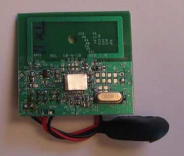
Click to zoom
Application Details
- Equipment Class
- DSC - Part 15 Security/Remote Control Transmitter
- Date of Grant
- Nov 29, 2010
- Application Purpose
- Original Equipment
- Date of Application
- Nov 14, 2010
- Equipment Note
- Transmitter Module
- Frequency Range
- 433.92000000 - 433.92000000
- Country
- United States
Documents & Files
Document Text
Text extracted from the exhibit documents filed with the FCC. Open a document above to read the original.
Users Manual
P O Box 159 • Crestwood, KY 40014 • (502) 243-0042 • (502) 243-0039 fax www.e2di.com • [email protected] Technical User Manual for 433.92 mHz transmitter module 1. Analog voltage may appear on GP4 or GP2. 2. Analog voltage range is between 0 and 5 volts. 3. Sample time is modulated and fixed between 11 seconds and 19 seconds. 4. Power to the module is supplied between VBAT2 and GND 5. With use of a 5 volt regulator the unregulated DC voltage should be in the range of 6 to 10 volts DC. It is expected that the unit will be battery powered, which is the way it was tested. If it is wall powered, the user must insure compliance with conducted emissions. 6. GGP3 is the reset control for the module 7. Analog voltage to be sampled is applied on GGP4, GGP2, and GGP0 (single ended analog inputs) 8. GGP1 is the power control for the analog electronics 9. VCC is regulated voltage FCC Regulatory Information This device complies with part 15 of the FCC Rules. Operation is subject to the following two conditions: 1. This device may not cause harmful interference, and 2. This device must accept any interference received, including interference that may cause undesired operation. Changes or modifications not expressly approved by the party responsible for compliance could void the user’s authority to operate the equipment.
Attestation Statements
P O Box 159 • Crestwood, KY 40014 • (502) 243-0042 • (502) 243-0039 fax www.e2di.com • [email protected] November 29, 2010 Doug ATCB All of the YVGWS4TX modules will be sold with shielding as shown in the external Exhibits Frederick G Kaestner
Attestation Statements
P O Box 159 • Crestwood, KY 40014 • (502) 243-0042 • (502) 243-0039 fax www.e2di.com • [email protected] November 29, 2010 Doug ATCB All of the YVGWS4TX modules will be sold with battery connector as shown in the external and internal Exhibits Frederick G Kaestner
Cover Letter(s)
dBi Corporation 216 Hillsboro Ave. Lexington, KY 40511-2105 10dBi030a page 1 of 2 November 4, 2010 Two Dimensional Instruments 6901 Briarhill Rd Crestwood, KY 40014 Gentlemen; Test report 10dBi030a, dated November 4, 2010, replaces test report 10dBi030, dated October 12, 2010, in its entirety. The attached test report contains the results of the electromagnetic compatibility (EMC) testing that dBi Corporation performed on the TVRFL4 Base Station, the WS4HETMETM, WS4HETC, WS4IPR, WS4ITMIHM, and WS4HITMIHM Wireless Sensors, and the WS4TX Transmitter Module on September 4-October 10, 2010. We evaluated TVRFL4 serial number (S/N) 10 (with ThermaViewer RF S/N WS11652 as auxiliary equipment), WS4HETMETM S/N 5, WS4HETC S/N 1, WS4IPR S/N 7, and WS4ITMIHM S/N 6, and WS4HITMIHM S/N 8, using: • ANSI C63.4-2003 to determine their compliance with the US’s FCC 47 CFR Part 15- 2008. • CAN/CSA-CEI/IEC CISPR 22:02 to determine their compliance with Canada’s Industry Canada (IC) ICES-003:2004. To get the TVRFL4 and ThermaViewer RF to comply with these standards, we had to put a Steward 28A0640-0A2 snap-on ferrite on the ThermaViewer RF’s Data Cable. With this modification, the data in the attached report shows that these units comply with all of the: • FCC 47 CFR Part 15-2008 Class B requirements for unintentional radiators. • IC ICES-003 Class B requirements for unintentional radiators. Therefore all of these units— including the ThermaViewer RF— may be considered FCC/IC Class B Verified. We evaluated WS4TX Transmitter Module S/N 11, using: • ANSI C63.4-2003 to determine its compliance with the US’s FCC 47 CFR Part 15- 2008. • RSS-Gen Issue 2 (June 2007) to determine its compliance with Canada’s Industry Canada (IC) RSS-210 Issue 7 (June 2007). To get the WS4TX to comply with these standards, we had to make R14 = 39 kohms, C1 = 0.1uF, and C19 = 330pF. With these modifications, the data in the attached report shows that the WS4TX meet all of the requirements for: • FCC Certification under FCC 47 CFR Part 15-2008 section 15.231(e). • IC Certification under RSS-210 Issue 7 (June 2007) section A1.1.5. dBi Corporation 216 Hillsboro Ave. Lexington, KY 40511-2105 10dBi030a page 2 of 2 Test report 10dBi030a contains: • Administrative information for the TVRFL4, WSHETMETM, WS4HETC, WS4IPR, WS4ITMIHM, WS4HITMIHM, and WS4TX. • A sample FCC/IC Declaration of Conformity (DoC) for the TVRFL4, WSHETMETM, WS4HETC, WS4IPR, WS4ITMIHM, and WS4HITMIHM. • Information relating to product RF Interference for the TVRFL4, WSHETMETM, WS4HETC, WS4IPR, WS4ITMIHM, WS4HITMIHM, and WS4TX. • Radiated and conducted interference test results for the TVRFL4, WSHETMETM, WS4HETC, WS4IPR, WS4ITMIHM, WS4HITMIHM, and WS4TX. • Descriptions of the test and measuring equipment used. • Pictures of the test setups. If you need any additional information or explanations, please contact me directly. Sincerely, John R. Barnes KS4GL, PE, NCE, NCT, ESDC Eng, ESDC Tech, PSE, SM IEEE President, dBi Corporation
Cover Letter(s)
THIS MUST BE SIGNED BY THE APPLICANT AND SHOULD BE PLACED ON APPLICANTS LETTERHEAD ONLY IF AGENT IS SUBMITTING APPLICATION 03/28/09 - 2 Request for Confidentiality Date: November 8, 2010 Subject: Confidentiality Request for FCC ID: YVGWS4TX Pursuant to FCC 47 CRF 0.457(d) and 0.459 and IC RSP-100, Section 10, the applicant requests that a part of the subject FCC application be held confidential. Type of Confidentiality Requested Exhibit Short Term x Permanent Block Diagrams Short Term External Photos Short Term Permanent* 1 Internal Photos Short Term x Permanent Operation Description/Theory of Operation Short Term Permanent Parts List & Placement/BOM Short Term Permanent Tune-Up Procedure Short Term x Permanent Schematics Short Term Test Setup Photos Short Term Permanent* User’s Manual *Note: ______(Insert Explanation as Necessary)______ Two Dimensional Instruments, LLC., has spent substantial effort in developing this product and it is one of the first of its kind in industry. Having the subject information easily available to "competition" would negate the advantage they have achieved by developing this product. Not protecting the details of the design will result in financial hardship. Permanent Confidentiality: The applicant requests the exhibits listed above as permanently confidential be permanently withheld from public review due to materials that contain trade secrets and proprietary information not customarily released to the public. Short-Term Confidentiality: The applicant requests the exhibits selected above as short term confidential be withheld from public view for a period of ___(specify number of days not to exceed 180 ) 2 ___ days from the date of the Grant of Equipment Authorization and prior to marketing. This is to avoid premature release of sensitive information prior to marketing or release of the product to the public. Applicant is also aware that they are responsible to notify ATCB in the event information regarding the product or the product is made available to the public. ATCB will then release the documents listed above for public disclosure pursuant to FCC Public Notice DA 04-1705. Sincerely, By: Frederick G Kaestner, Jr. (Signature/Title 3 ) (Print name) 1 - The asterisked items (*) require further justification before permanent confidentiality will be allowed. These also currently r equire review by the FCC under their Permit-But-Ask policy before the grant is issued and can delay completion of an application. Further justification should be added to the note above. One such example for a potted device would be: “The EUT is FULLY potted using a non-removable epoxy based material. Removal of potting material causes irreparable damage to internal circuitry. See photographs exhibits that outline the device before and after potting.” 2 - Please refer to h ttp://atcb.com/publicdocs/Memo-Short-Term-Vs-Standard-Confidentiality.pdf for complete details. 3 - Must be signed by applicant contact given for applicant on the FCC site, or by the authorized agent if an appropriate authorized agent letter has been provided. Letters should be placed on appropriate letterhead.
Cover Letter(s)
P O Box 159 • Crestwood, KY 40014 • (502) 243-0042 • (502) 243-0039 fax www.e2di.com • [email protected] ATCB October 28, 2010 Dear Application Examiner, Two Dimensional Instruments WS4TX , FCC ID: YVGWS4TX, would like to have your authorization for Module Approval specific to the low power transmitter. The requirements of Public Notice DA00-1407 have been met and shown on the following statement s. 1. “The modular transmitter must have its own RF shielding.”: The modular transmitter has an integral RF shielding in the PCB to ensure that the module does not have to rely upon the shielding provided by the device into which it is installed in order for all modular transmitter emissions to comply with Part 15 limits. It is also intended to prevent coupling between the RF circuitry of the module and any wires or circuits in the device into which the module is installed. 2. “The modular transmitter must have buffered modulation/data inputs.” Data inputs are buffered by the rfPIC12F675 input circuitry and the transmitter is under software control. This ensures the data packet length and data rate is limited and remains compliant with Part 15 requirements. Any analog data is buffered and converted to a digital form for transmission, thus preventing possible over modulation. 3. “The modular transmitter must have its own power supply regulation.” The module has an on board voltage regulator which powers the microcontroller and transmitter circuitry. 4. “The modular transmitter must comply with the antenna requirements of section 15.203 and 15.204(C).” The antenna is a PCB trace on the module and is permanently attached to the module. 5. “The modular transmitter must be tested in a stand-alone configuration” The module was tested in a stand-alone configuration using a typical interface PCB to provide battery power and signals to the module for testing. 6. “The modular transmitter must be labeled with its own FCC ID number.” P O Box 159 • Crestwood, KY 40014 • (502) 243-0042 • (502) 243-0039 fax www.e2di.com • [email protected] See label and label location drawing contained in this application. The label is visible on the module and appropriate instructions are given in the user manual for end users who incorporate the module in the final product. 7. “The modular transmitter must comply with any specific rule or operating requirements applicable to the transmitter and the manufacturer must provide adequate instructions along with the module to explain any such requirements.” The WS4TX module is software controlled and the software controlling the transmitter functionality is not controllable by the end-user and thus all modules will meet these requirements. 8. “The modular transmitter must comply with any applicable RF exposure requirements.” The WS4TX module meets all the requirements and is shown in dBI Corporation Test Report. Frederick G Kaestner CEO
External Photos
External Photos Front and Back
ID Label/Location Info
Artwork for label ID to be placed in silkscreen on the 433.92 mHz transmitter board. FCC ID YVGWS4TX IC 9300AWS4TX (8 pt ty pe Arial Unic ode MS font)
Internal Photos
Internal Photos Front and Back
Test Report
dBi Corporation FCC/IC Verification Test Report Two Dimensional Instruments TVRFL4 Base Station, and WS4HETMETM, WS4HETC, WS4IPR, WS4ITMIHM, and WS4HITMIHM Wireless Sensors FCC/IC Certification Test Report Two Dimensional Instruments WS4TX Transmitter Module Report Number 10dBi030a November 4, 2010 This test report replaces test report 10dBi030, dated October 12, 2010, in its entirety. Test Laboratory Certificate Number 1985.01 dBi Corporation 10dBi030a Page 2 of 43 ADMINISTRATIVE INFORMATION Historical record: Because dBi Corporation is a testing entity, and not a manufacturer, this original test report of the TVRFL4 Base Station, the WS4HETMETM, WS4HETC, WS4IPR, WS4ITMIHM, and WS4HITMIHM Wireless Sensors, and the WS4TX Transmitter Module, is being transmitted to the manufacturer, Two Dimensional Instruments. dBi will keep a copy for its historical records and to satisfy A2LA-Audit requirements. We strongly recommend archiving the units that we tested, to help answer any future inquiries about the products. Retention of records: The FCC requires the records for a Class A or Class B product to be retained by the responsible party for at least two years after the manufacture of said product has been permanently discontinued. These records should include the original certification or verification product report, quality audit data, and the test procedures used. The European Union requires the Declaration of Conformity (DoC) and all supporting data for a product bearing the CE Marking to be retained, and available for inspection by enforcement authorities, for 10 years after last placing the product on the market. Australia and New Zealand require the Declaration of Conformity, test reports, a description of the product, documentation that clearly identifies the product, and paperwork showing the product’s brand name, model number, etc. to be kept for at least five years after the product ceases to be supplied to Australia or New Zealand. Measurement uncertainties: The Lexmark Electromagnetic Compatibility Laboratory (EMC Lab) has a documented calculation of the measurement uncertainties associated with tests performed at the Lexmark site. Ongoing compliance: This report applies only to the samples tested. Two Dimensional Instruments has full responsibility for ensuring that the modifications made to these samples are included in all production models of the TVRFL4, WS4HETMETM, WS4HETC, WS4IPR, WS4ITMIHM, WS4HITMIHM, and WS4TX, so that they comply with the FCC/IC requirements, and continue to comply throughout their manufacturing life. Two Dimensional Instruments should check any changes to the products that could change their interference profiles. A2LA approval: dBi Corporation has been accredited by the American Association for Laboratory Accreditation (A2LA) for Radiated Emissions and Conducted Emissions, Electromagnetic Interference, and Electrostatic Discharge testing. Copies of our Accreditation Certificate and Scope of Accreditation follow. dBi Corporation 10dBi030a Page 3 of 43 The Federal Communications Commission (FCC) recognized the Lexmark site as meeting section 2.948 of the FCC Rules in letters dated October 30, 2007 (Registration No. 949691) and January 14, 2010 (Registration No. 991141). Industry Canada recognizes the Lexmark site in letters dated November 16, 2009 (number 2376A-1) and March 2, 2009 (number 2376A-3). Please note: This report may be copied as needed, as long as it is copied in its entirety. dBi Corporation 10dBi030a Page 4 of 43 dBi Corporation 10dBi030a Page 5 of 43 dBi Corporation 10dBi030a Page 6 of 43 dBi Corporation 10dBi030a Page 7 of 43 dBi Corporation 10dBi030a Page 8 of 43 dBi Corporation 10dBi030a Page 9 of 43 ADMINISTRATIVE DATA Manufacturer: Two Dimensional Instruments 6901 Briarhill Rd Crestwood, KY 40014 Appliance/Product: Base Station and four Wireless Sensors Model/Type Number: TVRFL4, WS4HETMETM, WS4HETC, WS4IPR, WS4ITMIHM, and WS4HITMIHM Rating: 9VDC Power Line Filters and RF Suppression Components: see attached sheets. Measurements According to, and Sample Units Comply with: FCC 47 CFR Part 15-2008 Class B for the US, using ANSI C63.4:2003, with 30 dBuV/m - 26,58 dBuV/m = 3.42dB margin for Radiated Emissions. Industry Canada (IC) ICES-003:2004 Class B for Canada, using CAN/CSA-CEI/IEC CISPR 22:02, with with 30 dBuV/m - 26,58 dBuV/m = 3.42dB margin for Radiated Emissions. Appliance/Product: Transmitter Module Model/Type Number: WS4TX FCC ID: YVGWS4TX Rating: 9VDC Power Line Filters and RF Suppression Components: see attached sheets. Measurements According to, and Sample Unit Complies with: FCC 47 CFR Part 15-2008 for the US, using ANSI C63.4-2003, with 72.87 dBuV/m – 69.20 dBuV/m = 3.67dB margin for Radiated Emissions. RSS-210 Issue 7 (June 2007) for Canada, using RSS-Gen Issue 2 (June 2007), with 72.87 dBuV/m – 69.20 dBuV/m = 3.67dB margin for Radiated Emissions Measurement Equipment used: see attached sheets. Report Prepared By: John R. Barnes KS4GL, PE, NCE, NCT, ESDC Eng, ESDC Tech, PSE, SM IEEE dBi Corporation 10dBi030a Page 10 of 43 Testing Performed by: dBi Corporation 216 Hillsboro Avenue Lexington, KY 40511-2105, USA on September 4-October 10, 2010 at:Lexmark International, Inc. Development Lab. Lexington, KY 40550, USA Reviewed and Approved by: John R. Barnes, KS4GL, PE, NCE, NCT, ESDC Eng, ESDC Tech, PSE, SM IEEE SIGNED_______________________________ Date: __ November 4,. 2010__ John R. Barnes, PRESIDENT dBi Corp. dBi Corporation 10dBi030a Page 11 of 43 November 4, 2010 To whom it may concern: We, Two Dimensional Instruments, declare under our sole responsibility that the TVRFL4 Base Station, and the WS4HETMETM, WS4HETC, WS4IPR, WS4ITMIHM, and WS4HITMIHM Wireless Sensors, to which this declaration relates, conform with the protection requirements of FCC Part 15 for the US, and Industry Canada (IC) ICES-003 for Canada, for unintentional radiators. This FCC/IC Declaration of Conformity (DoC) is based on the TVRFL4, WS4HETMETM, WS4H…
Text truncated - open the document above for the full version.
Test Setup Photos
RADIATED EMISSIONS TEST CONFIGURATION WS4TX 5m SEMIANECHOIC CHAMBER LEXMARK INTERNATIONAL, LEXINGTON KY VIEW FROM THE TURNTABLE DURING 30-1000MHZ TEST 5m SEMIANECHOIC CHAMBER LEXMARK INTERNATIONAL, LEXINGTON KY
Contact Information
Applicant
Frederick Guy Kaestner(Mr)
Technical Contact
Two Dimemsional Instruments LLCMike Lhamon
[email protected]859 271 7521
4621 Riverman Way · Lexington · United States
Test Firm
dBi CorporationJohn Barnes
Technical Specifications
| # | Rule Parts | Frequency Range | Power Output |
|---|---|---|---|
| 1 | 15.231,15.231(e) | 433.92 MHz - 433.92 MHz | - |