Text extracted from the exhibit documents filed with the FCC. Open a document above to read the original.
Copyright © 2006 by Elenco ® Electronics, Inc. All rights reserved. No part of this book shall be reproduced by753131 any means; electronic, photocopying, or otherwise without written permission from the publisher. -1- Basic Troubleshooting1 Parts List2 How to Use It3 About Your Snap Circuits Parts4 How It Works5, 6 General Operating Instructions6 DO’s and DON’Ts of Building Circuits7 Advanced Troubleshooting8 Project 19 Project 210 Projects 3, 411 Projects 5, 612 Project 7, 813 Projects 9, 1014 Projects 11, 1215 Projects 13, 1416 Projects 15, 1617 Projects 17, 1818 Project 19, 2019 Projects 21-2320 Other Snap Circuits Products21 Bonus Projects B1-B322 WARNING: SHOCK HAZARD- Never connect Snap Circuits to the electrical outlets in your home in any way! Table of Contents 1. Most circuit problems are due to incorrect assembly, always double-check that your circuit exactly matches the drawing for it. 2. Be sure that parts with positive/negative markings are positioned as per the drawing. 3. Be sure that all connections are securely snapped. 4. Try replacing the batteries in the Rover body and remote control unit. 5. Keep the wheels clean and free of lint, thread, or dirt. Elenco ® Electronics is not responsible for parts damaged due to incorrect wiring. Basic Troubleshooting Note: If you suspect you have damaged parts, you can follow the Advanced Troubleshooting procedure on page 8 to determine which ones need replacing. BATTERIES: Use only 1.5V AA type in the Rover body and 9V in the remote control (not included). Insert batteries with correct polarity. Non-rechargeable batteries should not be recharged. Rechargable batteries should only be charged under adult supervision, and should not be recharged while in the product. Do not mix alkaline, standard (carbon-zinc), or rechargeable (nickel-cadmium) batteries. Remove batteries when they are used up. Do not short circuit the battery terminals. Never throw batteries in a fire or attempt to open its outer casing. Batteries are harmful if swallowed, so keep away from small children. WARNING:Always check your wiring before turning on a circuit. Never leave a circuit unattended while the batteries are installed. Never connect additional batteries or any other power sources to your circuits. Warning to Snap Circuits Owners:Do not use parts from other Snap Circuits sets with this kit. The Snap Rover uses higher voltage which could damage those parts. Page 22 and our web site www.snapcircuits.net has approved circuits that you can use. ! Note:If you have a more advanced model, there are additional part lists in the other project manuals. Important:If any parts are missing or damaged, DO NOT RETURN TO RETAILER. Call toll-free (800) 533-2441 or e-mail us at: [email protected]. Customer Service • 150 Carpenter Ave. • Wheeling, IL 60090 U.S.A. Qty.IDNameSymbolPart #Qty.IDNameSymbolPart # 1Rover Body6SCRB2470μF Capacitor6SCC5 1 Remote Control Unit Antenna 6SCTX1 6SCTX1A 1 White LED 6SCD4 1 Base Grid (11.0” x 7.7”) 6SCBG1 100ΩResistor 6SCR1 21-Snap Wire6SC014 1KΩResistor 6SCR2 62-Snap Wire6SC021 R/C Receiver 6SCRX1 23-Snap Wire6SC031Slide Switch6SCS1 14-Snap Wire6SC041Motor Control IC6SCU8 15-Snap Wire6SC051Horn6SCW1 16-Snap Wire6SC06 1 1 1 Jumper Wire (Orange) Jumper Wire (Yellow) Jumper Wire (Green) 6SCJ3A 6SCJ3B 6SCJ3C 17-Snap Wire6SC07 1 1 1 Jumper Wire (Purple) Jumper Wire (Gray) Jumper Wire (White) 6SCJ3D 6SCJ3E 6SCJ3F 10.02μF Capacitor6SCC11Decorative Decal721053 7 6 5 3 2 1 C1 C5 W1 U8 D4 -2- Parts List(Colors and styles may vary) Symbols and Numbers R1 R2 4 RX1 S1 You may order additional / replacement parts at our web site: www.snapcircuits.net Note: Colors may vary and areinterchangeable. -3- Install six “AA” batteries (not included) into the bottom of the Rover body and one 9V battery (not included) into the remote control unit. Install the antenna into the remote control unit by screwing it in. The R/C Snap Rover Kit uses building blocks with snaps to build the different electrical and electronic circuits in the projects. Each block has a function: there are switch blocks, LED blocks, different length wire blocks, etc. These blocks are in different colors and have numbers on them so that you can easily identify them. The circuit you will build is shown in color and numbers, identifying the blocks that you will use and snap together to form a circuit. For Example: This is the switch block which is green and has the marking on it. This is a wire block which is blue and comes in different wire lengths. This one has the number , , , , , or on it depending on the length of the wire connection required. There is also a 1-snap wire that is used as a spacer or for interconnection between different layers. A large clear plastic base grid is included with this kit to keep the circuit blocks together, it fits on top of the Rover body. You will see evenly spaced posts that the different blocks snap into, these keep your circuit together. The base has rows labeled A-G and columns labeled 1-10. Next to each part in every circuit drawing is a small number in black. This tells you which level the component is placed at. Place all parts on level 1 first, then all of the parts on level 2, then all of the parts on level 3, etc. Jumper wires are used to connect your circuits to the batteries and motors in the Rover body. Snap them on as shown in the projects. The colors are interchangeable, so it doesn’t matter which color you use. Note:While building the projects, be careful not to accidentally make a direct electrical connection across the + and – snaps for the batteries (a “short circuit”), as this may damage and/or quickly drain the batteries. How To Use It 2 Warning to Snap Circuits owners: Do not use parts from other Snap Circuits sets with this kit unless directed to do so. The Snap Rover uses higher voltage which could damage those parts. Page 22 and our web site www.snapcircuits.net has approved circuits that you can use. 3 4 5 6 7 S1 Front of Rover Anten…
Text truncated - open the document above for the full version.
SCS-F18: Project and Product Certification Representative Authorization Letter Page 1 of 2 Rev 2.0 2206 Ringwood Avenue San Jose, CA 95131 Tel: 408-526-1188 Fax: 408-526-1088 Email: [email protected] Project and Product Certification Representative Authorization Letter Revision History Reason for Amendment (current / obsolete) From To Approved Date Initial Release (current) 1.0 1.0 Nov-14-2006 Revised wording (current) 1.0 2.0 Sept–25-2007 SCS-F18: Project and Product Certification Representative Authorization Letter Page 2 of 2 Rev 2.0 Elenco Electronics Inc. 150 Carpenter Avenue, Wheeling, IL 60090. Tel: 1-847-541 3800 Fax: 1-847-520 0085 Web site: www.elenco.com E-Mail: [email protected] 2010-10-13 To: SIEMIC, INC. 2206 Ringwood Avenue, San Jose, CA 95131 USA Dear Sir/Madam, Re: Project and Product Certification Representative Authorization Letter We, Elenco Electronics, Inc.hereby authorize SIEMIC, INC. to act as a Certification Body for certifying for the following project(s): Product:SNAP ROVER Item: SCROV-10 We affirm that between SIEMIC and Elenco Electronics Inc, any difference in understanding, including test plan, measurement methods, applicable standards and relevant procedures and processes have been resolved prior to commencement of testing activities. Sincerely, Client’s name / title : Mr. James Cecchin Contact information / address : Elenco Electronics Inc. 150 Carpenter Ave. Wheeling IL 60090. Tel: 1-847-541 3800
SCS-F19: Confidentiality Request Letter Page 1 of 2 Rev 2.0 2206 Ringwood Avenue San Jose, CA 95131 Tel: 408-526-1188 Fax: 408-526-1088 Email: [email protected] Confidentiality Request Letter Revision History Reason for Amendment (current / obsolete) From To Approved Date Initial Release (current) 1.0 1.0 Nov-14-2006 Adding CFR 2.459 1.0 2.0 August – 11 - 2008 SCS-F19: Confidentiality Request Letter Page 2 of 2 Rev 2.0 Elenco Electronics Inc. 150 Carpenter Avenue, Wheeling, IL 60090. Tel: 1-847-541 3800 Fax: 1-847-520 0085 Web site: www.elenco.com E-Mail: [email protected] 2010-10-13 To: Federal Communications Commission Authorization and Evaluation Division 7435 Oakland Mills Road Columbia, MD Subject: Permanent Confidentiality Request for FCC ID: YVISCROV-10 We hereby request confidential treatment of information accompanying this application as outlined below: - Block Diagrams - Schematics - Operational description The above materials contain trade secrets and proprietary information not customarily released to the public. The public disclosure of these materials may be harmful to the applicant and provide unjustified benefits to its competitors. The applicant understands that pursuant to Section 0.457 & 0.459 of the Rules, disclosure of this application and all accompanying documentation will not be made before the date of the Grant for this application. Sincerely, Client’s name / title : Mr. James Cecchin Contact information / address : Elenco Electronics Inc. 150 Carpenter Ave. Wheeling IL 60090. Tel: 1-847-541 3800
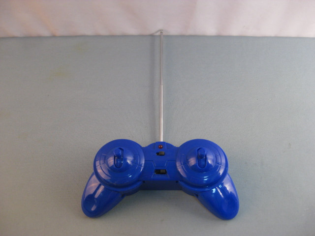
1 Photographs - EUT Construction Details (Test item No.: SCROV-10)
. SIZE: 21.5MM*31.5MM FCC ID:YVISCROV-10 This device complies with Part 15 of the FCC Rules .Operation is subject to the following two conditions:(1)this device may not cause harmful interference, and(2) this device must accept any interference received, including interference that may cause undesired operation.
Report No.: SZEMO10090609801 Page : 1 of 9 Authorized Signature: Jack Zhang Laboratory Manager The manufacturer should ensure that all products in series production are in conformity with the product sample detailed in this report. If the product in this report is used in any configuration other than that detailed in the report, the manufacturer must ensure the new system complies with all relevant standards. Any mention of SGS International Electrical Approvals or testing done by SGS International Electrical Approvals in connection with, distribution or use of the product described in this report must be approved by SGS International Electrical Approvals in writing. The report must not be used by the client to claim product certification, approval, or endorsement by NVLAP, NIST, or any agency of the federal government. All test results in this report can be traceable to National or International Standards. “This document is issued by the Company subject to its General Conditions of Service printed overleaf, available on request or accessible at www.sgs.com/terms_and_conditions.htm and, for electronic format documents, subject to Terms and Conditions for Electronic Documents at www.sgs.com/terms_e-document.htm. Attention is drawn to the limitation of liability, indemnification and jurisdiction issues defined therein. Any holder of this document is advised that information contained hereon reflects the Company’s findings at the time of its intervention only and within the limits of Client’s instructions, if any. The Company’s sole responsibility is to its Client and this document does not exonerate parties to a transaction from exercising all their rights and obligations under the transaction documents. This document cannot be reproduced except in full, without prior written approval of the Company. Any unauthorized alteration, forgery or falsification of the content or appearance of this document is unlawful and offenders may be prosecuted to the fullest extent of the law. Unless otherwise stated the results shown in this test report refer only to the sample(s) tested and such sample(s) are retained for 90 days only.” SGS-CSTC Standards Technical Services Ltd. No. 1 Workshop, M-10, Middle section, Science & Technology Park, Shenzhen, Guangdong, China 518057 Telephone: +86 (0) 755 2601 2053 Fax: +86 (0) 755 2671 0594 Email: [email protected] FCC REPORT Application No. : SZEMO100906098ET (SGS SZ No.: SZTYR100901355EM) Applicant: Elenco Electronics,Inc Item NO. SCROV-10 Product Name: Snap Rover Operation Frequency: 27.145MHz FCC ID: YVISCROV-10 Standards: FCC PART 15, SUBPART-C : 2009 Section 15.227 Date of Receipt 2010-09-21 Date of Test 2010-09-22 to 2010-09-29 Date of Issue 2010-09-30 Test Result : PASS * * In the configuration tested, the EUT complied with the standards specified above. “This document is issued by the Company subject to its General Conditions of Service printed overleaf, available on request or accessible at www.sgs.com/terms_and_conditions.htm and, for electronic format documents, subject to Terms and Conditions for Electronic Documents at www.sgs.com/terms_e-document.htm . Attention is drawn to the limitation of liability, indemnification and jurisdiction issues defined therein. Any holder of this document is advised that information contained hereon reflects the Company’s findings at the time of its intervention only and within the limits of Client’s instructions, if any. The Company’s sole responsibility is to its Client and this document does not exonerate parties to a transaction from exercising all their rights and obligations under the transaction documents. This document cannot be reproduced except in full, without prior written approval of the Company. Any unauthorized alteration, forgery or falsification of the content or appearance of this document is unlawful and offenders may be prosecuted to the fullest extent of the law. Unless otherwise stated the results shown in this test report refer only to the sample(s) tested and such sample(s) are retained for 90 days only.” Report No.: SZEMO10090609801 Page : 2 of 9 SGS-CSTC Standards Technical Services Ltd. 2 Contents Page 1 COVER PAGE 1 2 CONTENTS.............................................................................................................................................................. 2 3 TEST SUMMARY.................................................................................................................................................... 3 4 GENERAL INFORMATION.................................................................................................................................... 4 4.1 CLIENT INFORMATION............................................................................................................................................. 4 4.2 GENERAL DESCRIPTION OF E.U.T. .......................................................................................................................... 4 4.3 E.U.T. ENVIRONMENT AND TEST MODES................................................................................................................ 4 4.4 TEST LOCATION...................................................................................................................................................... 5 4.5 OTHER INFORMATION REQUESTED BY THE CUSTOMER........................................................................................... 5 4.6 TEST FACILITY........................................................................................................................................................ 5 4.7 TEST INSTRUMENTS LIST........................................................................................................................................ 6 5 TEST RESULT & MEASUREMENT DATA......................................................................................................... 7 5.1 ANTENNA REQUIRMENT................…
Text truncated - open the document above for the full version.
1 Photographs - Test Setup (Test item No.: SCROV-10) Radiated Emission
| # | Rule Parts | Frequency Range | Power Output |
|---|---|---|---|
| 1 | 15C | 27.145 MHz - 27.145 MHz | - |

SNAP CIRCUITS
Equipment Class
DTS - Digital Transmission System
