YVK-802NRUMSVQ802.11n USB Module
QVS Marketing Inc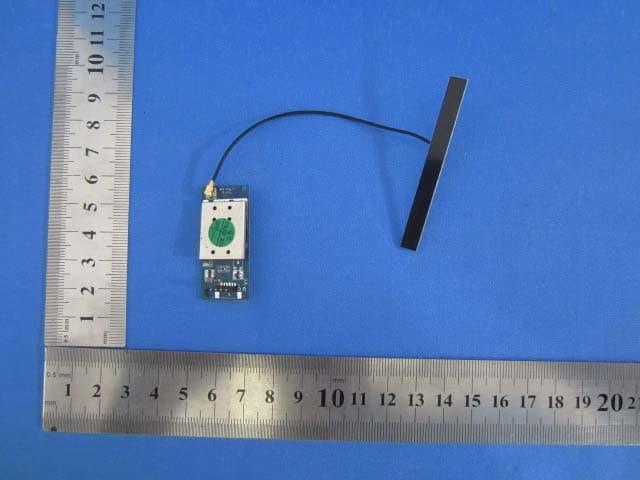
Click to zoom
Application Details
- Equipment Class
- DTS - Digital Transmission System
- Date of Grant
- Oct 26, 2011
- Application Purpose
- Original Equipment
- Date of Application
- Oct 26, 2011
- Equipment Note
- 802.11n USB Module
- Frequency Range
- 2422.00000000 - 2452.00000000
- Company
- QVS Marketing Inc
- Country
- United States
Documents & Files
Document Text
Text extracted from the exhibit documents filed with the FCC. Open a document above to read the original.
Users Manual
User’s Manual Version 1.7 TS-802NRUMS VQ 150Mbps USB Module User’s Manual A150bgn, TS-802NRUS VQ Wireless n Module Page 2 - Introduction Thank you for purchasing the IEEE 802.11n Wireless USB module. This Wireless module is easy to use and easy to setup. A typical Internet access application for the USB wireless module is shown as the following figure: User’s Manual A150bgn, TS-802NRUS VQ Wireless n Module Page 3 There are two different ways to access Internet: 1. With a wireless adaptor, receiving and transferring signal via a wireless router, then passed to an ADSL modem, then to local ISP (Internet service supplier) through a telephone line. 2. With a wireless adaptor, receiving and transferring signal via local AP (Access Point) or so called Hotpoint directly. Tips: An 802.11 LAN is based on a cellular architecture where the system is subdivided into cells, where each cell (called Basic Service Set or BSS) is controlled by a Base Station (called Access Point, or in short AP). Package Contents: One 54 Mbps 802.11b/g or 150Mbps or 300Mbps 802.11n USB Wireless Adapter. User’s Manual A150bgn, TS-802NRUS VQ Wireless n Module Page 4 User’s Manual. Antenna (external) Warranty The warrants for the end user (“Customer”) that this hardware product will be free from defects in workmanship and materials, under normal use and service, for twelve (12) months from the date of purchase from its authorized reseller. Information in this document is subject to change without prior notice. Installation To install the driver of the USB module, please use administrator user account to login before the following steps: Tips: the latest original drivers can be down loaded from the website of Ralink chipset manufacturer. The current website is http://www.ralink.com.tw/support.php. To find a correct driver, please identify the chipset type applied in the adapter you have. 1. For a 54Mbps 802.11b/g or a 150Mbps or 300Mbps 802.11n adapter, double click Ralink_***.exe program, which is located in the driver folder in the installation disc. Such as: G:\WiFi Driver\Windows Driver\ RT2070_RT307X.exe. Notes: Because Ralink often updates software, the drivers contained in the disc might be changed without prior notice. User’s Manual A150bgn, TS-802NRUS VQ Wireless n Module Page 5 2. Follow the instructions and prompts of the “InstallShield Wizard” to finish the driver installation: a. Select the “I accept the terms of the license agreements”, then click the “Next”. b. There shows a setup type window, you can select “Install driver only” or “Install driver and Ralink WALN utility” and then click the “Next”. User’s Manual A150bgn, TS-802NRUS VQ Wireless n Module Page 6 Tips: 1).The Windows XP utilizes a "Wireless Zero Configuration( WZC)" Service built into the operating system. Many wireless network adapter cards utilize this service. 2). Ralink- the chipset manufacturer has developed an utility for setting up wireless connection. If you select this item, you can switch between the Windows XP’s WZC service and the Ralink WLAN utility service later. c. Click the “Install” to confirm the installation, there shows the installation progress. User’s Manual A150bgn, TS-802NRUS VQ Wireless n Module Page 7 User’s Manual A150bgn, TS-802NRUS VQ Wireless n Module Page 8 d. Click “finish” to finish the driver installation. Wireless Connection 1. After finishing driver installation, insert the USB adapter to Notebook or PC that supports USB 2.0/1.1 interface. Remarks: Make sure to connect the adapter to an USB port on your computer directly rather than an USB hub. Although it might work when connecting with an USB hub, the likelihood of configuration problems will be higher. 2. The system shows a wireless utility icon in the Windows system tray, which locates in the bottom-right corner of your computer screen, and pops User’s Manual A150bgn, TS-802NRUS VQ Wireless n Module Page 9 up a message that indicates a new hardware is found and installed, something like this: Should the service " Wireless Zero 1. Double-click the utility icon or right click the icon and then select “View Available Wireless Networks” to launch the utility, the Wireless Network Connection window appears and displays your wireless network listed with the SSID you chose. Notes: Before configuring your WiFi access, you need to have your network’s SSID (service set identifier), Should the service " Wireless Zero Confi guration( WZC)" be applied. User’s Manual A150bgn, TS-802NRUS VQ Wireless n Module Page 10 security key and authentication type handy. Check the documentation coming with your router, ask your network administrator to get the information. 2. If you don't see your network, click “Refresh network list” in the upper left corner. If you are locating within the valid range of hotspots or wireless routers, all available networks will be recognized and listed automatically. Click your preferred network, and then click “Connect” in the lower right corner. 3. If the network security key hasn’t been inputted before, Windows XP prompts you to enter the network’s security key to access the wanted SSID. Type the encryption key that you wrote down earlier in both the Network key and Confirm network key boxes, User’s Manual A150bgn, TS-802NRUS VQ Wireless n Module Page 11 and then click “Connect”. Tips: If there are free hotspots, simply select the network you want from the list displayed, then click Connecting. It tries to launch your Internet browser —you should be connected to the Internet. If there is a pay hotspot, signing in or up will require either to enter your login information-if you‘re an existing customer, or to enter your credit card information for payment, it is just decided by you. Then clicking the Connecting, your default Internet browser will launch and take you to the service provider’s login page. Most providers have very simple and step-by-step instructions for you to sign up and then to be connected. Another way to access the servic…
Text truncated - open the document above for the full version.
Cover Letter(s)
SCS-F18: Project and Product Certification Representative Authorization Letter Page 1 of 2 Rev 2.0 2206 Ringwood Avenue San Jose, CA 95131 Tel: 408-526-1188 Fax: 408-526-1088 Email: [email protected] Project and Product Certification Representative Authorization Letter Revision History Reason for Amendment (current / obsolete) From To Approved Date Initial Release (current) 1.0 1.0 Nov-14-2006 Revised wording (current) 1.0 2.0 Sept–25-2007 SCS-F18: Project and Product Certification Representative Authorization Letter Page 2 of 2 Rev 2.0 QVS Marketing Inc. 2011-10-20 To: SIEMIC, INC. 2206 Ringwood Avenue, San Jose, CA 95131 USA Dear Sir/Madam, Re: Project and Product Certification Representative Authorization Letter We, QVS Marketing Inc. hereby authorize SIEMIC, INC. to act as a Certification Body for certifying for the following project(s): Product description : 802.11n USB Module Model name: TS-802NRUMSVQ We affirm that between SIEMIC and QVS Marketing Inc., any difference in understanding, including test plan, measurement methods, applicable standards and relevant procedures and processes have been resolved prior to commencement of testing activities. Sincerely, Client’s signature Client’s name / title Diane Sahleen / Sale manager Contact information / address Tel: 801-733-0073, Fax: 801-943-0287 E-mail: Diane @qvsmarketing.com Address: 10721 S. Hidden Ridge Lane Sandy Utah 84092
Cover Letter(s)
SCS-F19: Confidentiality Request Letter Page 1 of 2 Rev 2.0 2206 Ringwood Avenue San Jose, CA 95131 Tel: 408-526-1188 Fax: 408-526-1088 Email: [email protected] Confidentiality Request Letter Revision History Reason for Amendment (current / obsolete) From To Approved Date Initial Release (current) 1.0 1.0 Nov-14-2006 Adding CFR 2.459 1.0 2.0 August – 11 - 2008 SCS-F19: Confidentiality Request Letter Page 2 of 2 Rev 2.0 QVS Marketing Inc. 2011-10-20 To: Federal Communications Commission Authorization and Evaluation Division 7435 Oakland Mills Road Columbia, MD Confidentiality Request regarding application for certification of FCC ID: YVK-802NRUMSVQ We hereby request confidential treatment of information accompanying this application as outlined below: - Schematics - Block Diagram - Operational Description The above materials contain trade secrets and proprietary information not customarily released to the public. The public disclosure of these materials may be harmful to the applicant and provide unjustified benefits to its competitors. The applicant understands that pursuant to Section 0.457 & 0.459 of the Rules, disclosure of this application and all accompanying documentation will not be made before the date of the Grant for this application. Sincerely, Client’s signature Client’s name / title Diane Sahleen / Sale manager Contact information / address Tel: 801-733-0073, Fax: 801-943-0287 E-mail: Diane @qvsmarketing.com Address: 10721 S. Hidden Ridge Lane Sandy Utah 84092
Cover Letter(s)
QVS Marketing Inc. Date: 2011-10-20 To: Federal Communications Commission 7435 Oakland Mills Road Columbia, MD FCC ID: YVK-802NRUMSVQ To Whom It May Concern: This letter is to ascertain that QVS Marketing Inc. Product 802.11n USB Module has been the units used for conducting FCC compliance testing, the DoC part will be tested by FCC recognized test lab. If you have any question or concerns, pls. contact us. Sincerely, Client’s signature : Client’s name / title : Diane Sahleen / Sale manager Contact information / address : Tel: 801-733-0073, Fax: 801-943-0287 E-mail: [email protected] Address: 10721 S. Hidden Ridge Lane Sandy Utah 84092
Cover Letter(s)
SCS-F26 Modular Approval Letter Page 1 of 4 Rev 4.0 2206 Ringwood Avenue San Jose, CA 95131 Tel: 408-526-1188 Fax: 408-526-1088 Email: [email protected] Modular Approval Declaration Letter Revision History Reason for Amendment (current / obsolete) From To Approved Date Initial Release (Obsolete) 1.0 1.0 Dec-04-2006 Added IC Modular Letter (Obsolete) 1.0 2.0 Feb 16 2009 Add LMA and MA option (Obsolete) 2.0 3.0 April 14 2010 Revised per RSS Gen issue 3.0 3.0 4.0 Jan 12 2011 SCS-F26 Modular Approval Letter Page 2 of 4 Rev 4.0 QVS Marketing Inc. 2011-10-20 (802.11n USB Module) FCC ID: YVK-802NRUMSVQ is seeking FCC Authorization as a Single Modular transmitter / Single Limited Modular Approval (Please check one). The EUT meets the requirements for Single Modular approval / Single Limited Modular Approval (please check one) as detailed in FCC public Notice DA00-1407. Compliance to each of the requirements is described below : Questions are: 1. “The modular transmitter must have its own RF shielding.” Yes / No 2. “The modular transmitter must have buffered modulation/data inputs.” Yes / No 3. “The modular transmitter must have its own power supply regulation.” Yes / No 4. “The modular transmitter must comply with the antenna requirements of section 15.203 and 15.204(c).” Yes / No 5. “The modular transmitter must be tested in a stand-alone configuration.” Yes / No 6. “The modular transmitter must be labeled with its own FCC ID number.” Yes / No 7. “The modular transmitter must comply with any specific rule or operating requirements applicable to the transmitter and the manufacture must provide adequate instruction along with the module to explain any such requirements.” Yes / No 8. “The modular transmitter must comply with any applicable RF exposure requirements.” Yes / No Note: (1) LMA may be granted when one or more of the requirements in the table above cannot be demonstrated. LMA will also be issued in those instances where applicants can demonstrate that they will retain control over the final installation of the device, such that compliance of the end product is assured. In such cases, an operating condition on the LMA for the module must state that the module is only approved for use when installed in devices produced by a specific manufacturer. When LMA is sought, the application for equipment certification must specifically state how control of the end product into which the module will be installed, and will be maintained, such that full compliance of the end product is always ensured. (2) Host devices which contain separately certified modules do not need to be recertified, provided that they meet the following conditions: (i) The host device, as a stand-alone unit without any separately certified modules, complies with all applicable Radio Standards Specifications. (ii) The host device and all the separately certified modules it contains jointly meet the RF exposure compliance requirements of RSS-102, if applicable. (iii) The host device complies with the certification labeling requirements of each of the modules it contains. Note 1: Compliance of a module in its final configuration is the responsibility of the applicant. A host device will not be considered certified if the instructions regarding antenna configuration provided in the original description, of one or more separately certified modules it contains, were not followed. Example: A separately certified low-power transceiver module using Bluetooth technology which is housed in a desktop computer, laptop or peripheral does not require the overall system to be recertified, if the desktop computer, laptop or peripheral, as a stand-alone unit, complies with all applicable technical standards. Client’s signature Client’s name / title: Diane Sahleen / Sale manager Contact information / address: Tel: 801-733-0073, Fax: 801-943-0287, e-mail: Diane @qvsmarketing.com Address: 10721 S. Hidden Ridge Lane Sandy Utah 84092 SCS-F26 Modular Approval Letter Page 3 of 4 Rev 4.0 (Company letter head) (Date) mm/dd/yy (Product name) IC ID : , is seeking IC Authorization as a modular transmitter / Limited Modular Transmitter (Please check one). The EUT meets the requirements for modular approval / Limited Modular Approval (Please check one) as detailed in RSS GEN. Compliance to each of the requirements is described below: * Please provide a detailed explanation if the answer is “No.” a. The radio elements must have the radio frequency circuitry must be shielded. Physical/discrete and tuning capacitors may be located external to the shield, but must be on the module assembly. Yes / No b. The module shall have buffered modulation/data input(s) (if such inputs are provided) to ensure that the module will comply with the requirements set out in the applicable RSS standard under conditions of excessive data rates or over-modulation. Yes / No c. The module shall have its own power supply regulation on the module. This is to ensure that the module will comply with the requirements set out in the applicable standard regardless of the design of the power supplying circuitry in the host device which houses the module Yes / No d. The module shall comply with the provisions for external power amplifiers and antennas detailed in this standard. The equipment certification submission shall contain a detailed description of the configuration of all antennas that will be used with the module. Yes / No e. The module shall be tested for compliance with the applicable standard in a stand-alone configuration, i.e. the module must not be inside another device during testing Yes / No f. The module shall comply with the Category I equipment labelling requirements. Yes / No g. The module shall comply with applicable RSS-102 exposure requirements, which are based on the intended use/configurations. Yes / No h. (h) Is the modular device for an Industry Canada licensed exempt service? Yes / No Note: (3) LMA may be granted when one or more of the requirements in the table above…
Text truncated - open the document above for the full version.
Cover Letter(s)
2206 Ringwood Avenue, San Jose, CA 95131, USA Tel: +1(408) 526 1188, Fax: +1(408) 526 1088, Email: [email protected], URL: www.siemic.com Jan 13, 2011 To: FCC From: SIEMIC, INC. RE: Applicant: QVS Marketing Inc, FCC ID: YVK-802NRUMSVQ (grant issued date: 10/27/2011), Request for changes in FCC grant note. Changes on FCC grant notes Justification Replaced the FCC grant note "limited modular approval " with "Singular modular approval" The wrong wording “limited “was placed in the FCC grant instead of correct wording “singular”. Removed the FCC grant note sentences : “The WLAN radio is operating in a 1x1 Spatial Multiplexing MIMO configuration as described in this filing ” “This grant is valid only when the device is sold to OEM integrators and the OEM integrators are instructed to ensure that the end user has no manual instructions to remove or install the device. " According to customer, this device is NOT MIMO device and the device may sold to others not only OEM manufacturer so the both sentences were removed. Removed the FCC grant note “MO” According to customer, this device is NOT MIMO device so the “MO” was removed. Thank you, Choon Sian Ooi SIEMIC, INC. 2206 Ringwood Ave., San Jose, CA 95131 Tel: 408-526-1188 Ext 209 Fax: 408-526-1088
External Photos
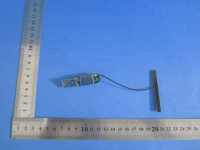
Report No: GTSE11100084301 Global United Technology Services Co., Ltd. Project No.: GTSE111000843RF 2nd Floor, Block No.2, Laodong Industrial Zone, Xixiang Road Baoan District, Shenzhen, China 518102 Telephone: +86 (0) 755 2779 8480 Fax: +86 (0) 755 2779 8960 Page 55 of 56 8 EUT Constructional Details
ID Label/Location Info
10mm (Length)* 8mm (Width) Product name: 802.11n USB Module Model No.: TS-802NRUMS VQ FCC ID: YVK-802NRUMSVQ
ID Label/Location Info
Label location
Internal Photos
Report No: GTSE11100084301 Global United Technology Services Co., Ltd. Project No.: GTSE111000843RF 2nd Floor, Block No.2, Laodong Industrial Zone, Xixiang Road Baoan District, Shenzhen, China 518102 Telephone: +86 (0) 755 2779 8480 Fax: +86 (0) 755 2779 8960 Page 56 of 56 ------end------
RF Exposure Info
1. RF Exposure Evaluation 1.1 Limits The criteria listed in the following table shall be used to evaluate the environment impact of human exposure to radio frequency (RF) radiation as specified in 1.1307(b) Limits for Maximum Permissible Exposure (MPE) Frequency range (MHz) Electric field strength (V/m) Magnetic field strength (A/m) Power density (mW/cm 2 ) Averaging time (minutes) (A) Limits for Occupational/Controlled Exposures 0.3–3.0 614 1.63 *(100) 6 3.0–30 1842/f 4.89/f *(900/f 2 ) 6 30–300 61.4 0.163 1.0 6 300–1500 f/300 6 1500–100,000 5 6 (B) Limits for General Population/Uncontrolled Exposure 0.3–1.34 614 1.63 *(100) 30 1.34–30 824/f 2.19/f *(180/f 2 ) 30 30–300 27.5 0.073 0.2 30 300–1500 f/1500 30 1500–100,000 1.0 30 f = frequency in MHz Friis Formula Friis transmission formula: Pd = (Pout*G)/(4*pi*r 2 ) Where Pd = power density in mW/cm 2 Pout = output power to antenna in mW G = gain of antenna in linear scale Pi = 3.1416 R = distance between observation point and center of the radiator in cm Pd id the limit of MPE, 1 mW/cm2 . If we know the maximum gain of the antenna and the total power input to the antenna, through the calculation, we will know the distance r where the MPE limit is reached. 1.2. Test Procedure Software provided by client enabled the EUT to transmit and receive data at lowest, middle and highest channel individually. 1.3. Test Result of RF Exposure Evaluation Type Frequency (MHz) Output power to antenna (mW) Power Density at R=20cm (mW/cm 2 ) Limit (mW/cm 2 ) Result 2412 31.84 0.0100 1.0 2437 29.92 0.0094 1.0 802.11b 2462 33.50 0.0106 1.0 2412 33.65 0.0106 1.0 2437 33.34 0.0105 1.0 802.11g 2462 31.55 0.0099 1.0 2412 33.96 0.0107 1.0 2437 32.28 0.0102 1.0 802.11n (H20) 2462 32.73 0.0103 1.0 2422 33.81 0.0107 1.0 2437 33.27 0.0105 1.0 802.11n (H40) 2452 32.21 0.0102 1.0 Pass Remark: antenna gain=2dBi
Test Report
Global United Technology Services Co., Ltd. Report No: GTSE11100084301 Authorized Signature: Stephen Guo Laboratory Manager This report details the results of the testing carried out on one sample. The results contained in this test report do not relate to other samples of the same product and does not permit the use of the GTS product certification mark. The manufacturer should ensure that all products in series production are in conformity with the product sample detailed in this report. This report may only be reproduced and distributed in full. If the product in this report is used in any configuration other than that detailed in the report, the manufacturer must ensure the new system complies with all relevant standards. Any mention of GTS International Electrical Approvals or testing done by GTS International Electrical Approvals in connection with, distribution or use of the product described in this report must be approved by GTS International Electrical Approvals in writing. This document cannot be reproduced except in full, without prior written approval of the Company. Any unauthorized alteration, forgery or falsification of the content or appearance of this document is unlawful and offenders may be prosecuted to the fullest extent of the law. Unless otherwise stated the results shown in this test report refer only to the sample(s) tested and such sample(s) are retained for 90 days only.” 1 Cover Page FCC REPORT Applicant: QVS Marketing Inc. Address of Applicant: 10721 S. Hidden Ridge Lane Sandy Utah 84092 Equipment Under Test (EUT) Product Name: 802.11n USB Module Model No.: TS-802NRUMS VQ FCC ID: YVK-802NRUMSVQ Applicable standards: FCC CFR Title 47 Part 15 Subpart C Section 15.247:2010 Date of sample receipt: Oct.13, 2011 Date of Test: Oct.17-18, 2011 Date of report issued: Oct.19, 2011 Test Result : PASS * * In the configuration tested, the EUT complied with the standards specified above. Report No: GTSE11100084301 Global United Technology Services Co., Ltd. Project No.: GTSE111000843RF 2nd Floor, Block No.2, Laodong Industrial Zone, Xixiang Road Baoan District, Shenzhen, China 518102 Telephone: +86 (0) 755 2779 8480 Fax: +86 (0) 755 2779 8960 Page 2 of 56 2 Version Version No. Date Description 00 Oct.19, 2011 Original Prepared By: Date: Oct.19, 2011 Project Engineer Check By: Date: Oct.19, 2011 Reviewer Report No: GTSE11100084301 Global United Technology Services Co., Ltd. Project No.: GTSE111000843RF 2nd Floor, Block No.2, Laodong Industrial Zone, Xixiang Road Baoan District, Shenzhen, China 518102 Telephone: +86 (0) 755 2779 8480 Fax: +86 (0) 755 2779 8960 Page 3 of 56 3 Contents Page 1 COVER PAGE..................................................................................................................................................... 1 2 VERSION.............................................................................................................................................................. 2 3 CONTENTS.......................................................................................................................................................... 3 4 TEST SUMMARY................................................................................................................................................ 4 5 GENERAL INFORMATION...............................................................................................................................5 5.1 CLIENT INFORMATION................................................................................................................................... 5 5.2 GENERAL DESCRIPTION OF E.U.T............................................................................................................... 5 5.3 TEST ENVIRONMENT AND MODE.................................................................................................................... 7 5.4 TEST FACILITY............................................................................................................................................... 7 5.5 TEST LOCATION............................................................................................................................................ 7 5.6 OTHER INFORMATION REQUESTED BY THE CUSTOMER.............................................................................. 7 5.7 TEST INSTRUMENTS LIST.............................................................................................................................. 8 6 TEST RESULTS AND MEASUREMENT DATA............................................................................................ 9 6.1 ANTENNA REQUIREMENT:............................................................................................................................. 9 6.2 CONDUCTED EMISSIONS............................................................................................................................. 10 6.3 CONDUCTED PEAK OUTPUT POWER.......................................................................................................... 13 6.4 6DB OCCUPY BANDWIDTH.......................................................................................................................... 18 6.5 POWER SPECTRAL DENSITY....................................................................................................................... 23 6.6 BAND EDGE................................................................................................................................................. 28 6.6.1 Conducted Emission Method............................................................................................................. 28 6.6.2 Radiated Emission Method................................................................................................................ 31 6.7 SPURIOUS EMISSION.................................................................................................................................. 36 6.…
Text truncated - open the document above for the full version.
Test Setup Photos
Report No: GTSE11100084301 Global United Technology Services Co., Ltd. Project No.: GTSE111000843RF 2nd Floor, Block No.2, Laodong Industrial Zone, Xixiang Road Baoan District, Shenzhen, China 518102 Telephone: +86 (0) 755 2779 8480 Fax: +86 (0) 755 2779 8960 Page 53 of 56 7 Test Setup Photo Conducted Emission Radiated Emission Report No: GTSE11100084301 Global United Technology Services Co., Ltd. Project No.: GTSE111000843RF 2nd Floor, Block No.2, Laodong Industrial Zone, Xixiang Road Baoan District, Shenzhen, China 518102 Telephone: +86 (0) 755 2779 8480 Fax: +86 (0) 755 2779 8960 Page 54 of 56
Contact Information
Applicant
Brad Sahleen(Sales Manager)
Test Firm
Global United Technology Service Co., LtdRobinson Lo
Technical Specifications
| # | Rule Parts | Frequency Range | Power Output |
|---|---|---|---|
| 2 | 15C | 2.42 GHz - 2.45 GHz | 33.80 mW |
Other Applications from QVS Marketing Inc
YVK-802NRUMS4
Sep 28, 2011802.11n USB Module
Equipment Class
DTS - Digital Transmission System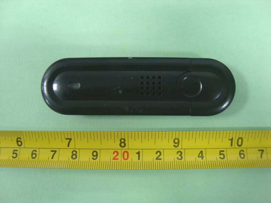
YVK-802GAUVC
Nov 12, 2010IEEE 802.11b/g WLAN USB Dongle
Equipment Class
DTS - Digital Transmission System