YXV16KTRANSMITTER
LoJack SafetyNet, Inc.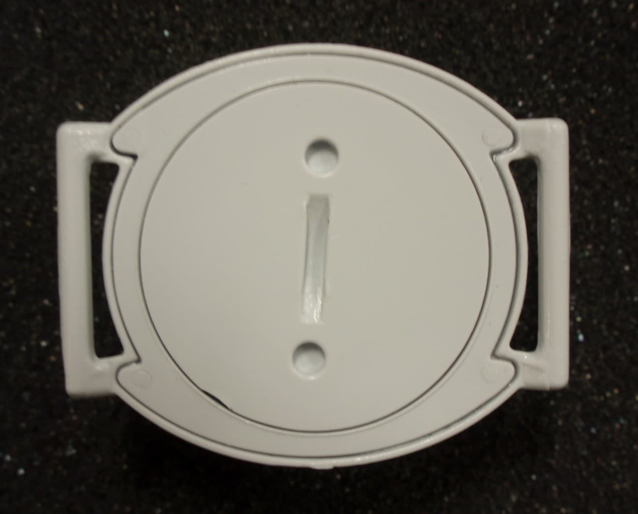
Click to zoom
Application Details
- Equipment Class
- TNB - Licensed Non-Broadcast Station Transmitter
- Date of Grant
- Mar 31, 2011
- Application Purpose
- Original Equipment
- Date of Application
- Mar 29, 2011
- Equipment Note
- TRANSMITTER
- Frequency Range
- 216.01250000 - 216.98750000
- Company
- LoJack SafetyNet, Inc.
- Country
- United States
Documents & Files
Document Text
Text extracted from the exhibit documents filed with the FCC. Open a document above to read the original.
Users Manual
Project Lifesaver - Client Transmitter Battery change, Maintenance & Daily Testing Project Lifesaver International | phone 757-546-5502 | www.projectlifesaver.org THIS INSTRUCTION PAGE MUST BE INCLUDED WITH ALL TRANSMITTERS SHIPPED TO PROJECT LIFESAVER AGENCIES SUMMARY 1. Client Transmitter Battery Change 2. FCC Title 47 Project Lifesaver - Client Transmitter Battery change, Maintenance & Daily Testing Project Lifesaver International | phone 757-546-5502 | www.projectlifesaver.org 1. Client Transmitter Battery Change 1. Unscrew battery cap with provided tool counter clockwise 2. Clean any debris from transmitter 3. Add the 30 day battery 4. Screw on battery cap clockwise 5. Screw cap on clockwise until it stops and cap is level with transmitter case bottom 6. Insert strap through pins on the bottom 7. Verify that transmitter is running with a VHF Transmitter Tester 8. Tester light will activate when placed on top of running transmitter Project Lifesaver - Client Transmitter Battery change, Maintenance & Daily Testing Project Lifesaver International | phone 757-546-5502 | www.projectlifesaver.org FCC Title 47[ Code of Federal Regulations] [Title 47, Volume 5, Parts 80 to End] [Revised as of October 1, 2000] From the U.S. Government Printing Office via GPO Access [CITE: 47CFR95.1017] [Page 564] TITLE 47--TELECOMMUNICATION COMMISSION (CONTINUED) PART 95--PERSONAL RADIO SERVICES--Table of Contents Subpart G--Low Power Radio Service (LPRS) Sec. 95.1017 Labeling requirements. (a) Each LPRS transmitting device shall bear the following statement in a conspicuous location on the device: ``This device may not interfere with TV reception or federal government radar, and must accept any interference received, including interference that may cause undesired operation.'' (b) Where an LPRS device is constructed in two or more sections connected by wires and marketed together, the statement specified in this section is required to be affixed only to the main control unit. (c) When the LPRS device is so small or for such use that it is not practicable to place the statement specified in the section on it, the statement must be placed in a prominent location in the instruction manual or pamphlet supplied to the user or, alternatively, shall be placed on the container in which the device is marketed.
Cover Letter(s)
Locator Systems Corp. 692 Sumas St., Victoria, BC, V8T 4S6, Canada Toll-free 1-866-863-5155 Tel 250-381-9425 Fax 250-381-9426 www.locatorsystemscorp.com Exhibit “Label Location” LSC Locator Systems International Label Location Justification a) There is limited space on the device for providing a proper label. The device is curved and contains many contoured surfaces. b) We cannot place an adhesive label on the outside of the device because Autistic Children are distracted by labels, stickers, or marks on the case. Experience has shown us that they will do almost anything to get these “markings” off the case. c) The battery compartment is designed to be easily opened, once a month, to have the battery replaced. The FCC and IC identifiers will be easily and readily viewable once the battery compartment is opened and the battery has been extracted. d) The device is sold without the battery cap attached to the unit. There is no battery installed in the device until it about to be used. The FCC identifier will be easily and readily viewable before the device is installed on the client Sincerely, Andrew Loen, P.Eng. 25 May 2010
External Photos
LoJack SafetyNet, Inc. FCC ID: YXV16K EXTERNAL PHOTOS
ID Label/Location Info
A) FCC ID and IC label and proposed location Proposed FCC ID number: YXV-16K Proposed IC ID number: 9408B-16K Proposed label location on inside of transmitter case
Test Report
FCC PART 95 LOW POWER RADIO SERVICE TEST REPORT APPLICANT LoJack SafetyNet, Inc. ADDRESS 200 Lowder Brook Drive Suite 100 Westwood, MA 02090 FCC ID YXV16K MODEL NUMBER L6 PRODUCT DESCRIPTION TRANSMITTER DATE SAMPLE RECEIVED 8/12/2010 DATE TESTED 8/24/2010 TESTED BY Nam Nguyen APPROVED BY Mario de Aranzeta TIMCO REPORT NO. 208AT11TestReport.doc TEST RESULTS PASS FAIL THE ATTACHED REPORT SHALL NOT BE REPRODUCED EXCEPT IN FULL WITHOUT THE WRITTEN APPROVAL OF TIMCO ENGINEERING, INC. 849 NW STATE ROAD 45 NEWBERRY, FL 32669 USA PH: 888.472.2424 OR 352.472.5500 FAX: 352.472.2030 EMAIL: [email protected] HTTP://WWW.TIMCOENGR.COM Certificate # 0955-01 Applicant: LoJack SafetyNet, Inc. FCC ID: YXV16K Report: Z:\L\LOJACK\208AT11\208AT11TestReport.doc Page 2 of 17 TABLE OF CONTENTS ATTESTATION STATEMENT ............................................................................ 3 REPORT SUMMARY ........................................................................................ 4 TEST ENVIRONMENT AND TEST SETUP ......................................................... 4 DUT DESCRIPTION ......................................................................................... 5 TEST EQUIPMENT LIST .................................................................................. 6 TEST PROCEDURE ......................................................................................... 7 TEST RESULT ............................................................................................... 10 RF POWER OUTPUT ............................................................................................................. 10 MODULATION CHARACTERISTICS ...................................................................................... 11 OCCUPIED BANDWIDTH ...................................................................................................... 12 SPURIOUS EMISSIONS AT ANTENNA TERMINALS (CONDUCTED)...................................... 14 FIELD STRENGTH OF SPURIOUS EMISSIONS (RADIATED) ................................................ 15 FREQUENCY STABILITY ............................................................................... 16 POWER LINE CONDUCTED INTERFERENCE....................................................................... 17 Applicant: LoJack SafetyNet, Inc. FCC ID: YXV16K Report: Z:\L\LOJACK\208AT11\208AT11TestReport.doc Page 3 of 17 ATTESTATION STATEMENT This equipment has been tested in accordance with the standards identified in the referenced test report. To the best of my knowledge and belief, these tests were performed using the measurement procedures described in this report and demonstrate that the equipment complies with the appropriate standards. No modifications were made to the equipment during testing in order to demonstrate compliance with these standards. Certificate #0955-01 All instrumentation and accessories used to test products for compliance to the indicated standards are calibrated regularly in accordance with ISO 17025 requirements. I attest that the necessary measurements were made by me or under my supervision, at Timco Engineering, Inc. located at 849 N.W. State Road 45, Newberry, Florida 32669 USA. Authorized by: Mario de Aranzeta Signature: Function: Engineer Date: 9/15/2010 Applicant: LoJack SafetyNet, Inc. FCC ID: YXV16K Report: Z:\L\LOJACK\208AT11\208AT11TestReport.doc Page 4 of 17 REPORT SUMMARY Disclaimer The test results relate only to the items tested. Purpose of Test To show the DUT in compliance with FCC CFR 47, Part 95 requirements for Low Power Radio Test Standards ANSI/TIA 603-C: 2004, FCC CFR 47 Part 95G, ANSI C63.4: 2003 TEST ENVIRONMENT AND TEST SETUP Test Facility All tests were conducted by Timco Engineering Inc. located at 849 NW State Road 45, Newberry, FL 32669 USA Laboratory Test Condition The temperature was 26ºC with a relative humidity of 50%. Deviation from the standards No deviation Modification to the DUT No modification was made. Test Exercise (software etc.) The DUT was placed in continuous transmitting mode of operation. System Setup Stand alone device. Applicant: LoJack SafetyNet, Inc. FCC ID: YXV16K Report: Z:\L\LOJACK\208AT11\208AT11TestReport.doc Page 5 of 17 DUT DESCRIPTION Manufactured by LoJack SafetyNet, Inc. Product Description TRANSMITTER FCC ID YXV16K M/N L6 S/N N/A Operating Freq 216.0125 – 216.9875 MHz Max. Output Pwr 0.010 W ERP Emission Designator(s) L1D Modulation on off keying (OOK) Power Source Battery coin cell Test Item Pre-production Type of DUT Portable Antenna Spec Permanently attached antenna Calculation of Designator(s) Bn = BK B = 1400 K=5 Bn = 5(1400) = 7000 Applicant: LoJack SafetyNet, Inc. FCC ID: YXV16K Report: Z:\L\LOJACK\208AT11\208AT11TestReport.doc Page 6 of 17 TEST EQUIPMENT LIST Device Manufacturer Model Serial Number Cal/Char Date Due Date 3-Meter Semi- Anechoic Chamber Panashield N/A N/A Listed 3/10/10 3/10/12 AC Voltmeter HP 400FL 2213A14499 CAL 3/23/09 3/23/11 Antenna: Dipole Kit Electro- Metrics TDA-30/1-4 153 CHAR 6/10/09 6/10/11 Frequency Counter HP 5385A 3242A07460 CAL 5/26/09 5/26/11 Hygro- Thermometer Extech 445703 0602 CAL 1/30/09 1/30/11 Modulation Analyzer HP 8901A 3435A06868 CAL 5/26/09 5/26/11 Digital Multimeter Fluke FLUKE-77-3 79510405 CAL 5/18/09 5/18/11 Analyzer Tan Tower Preamplifier HP 8449B-H02 3008A00372 CAL 11/21/09 11/21/11 Analyzer Tan Tower Quasi- Peak Adapter HP 85650A 3303A01690 CAL 11/22/09 11/22/11 Analyzer Tan Tower RF Preselector HP 85685A 3221A01400 CAL 11/21/09 11/21/11 Analyzer Tan Tower Spectrum Analyzer HP 8566B Opt 462 3138A07786 3144A20661 CAL 11/24/09 11/24/11 Temperature Chamber Tenney Engineering TTRC 11717-7 CHAR 4/25/10 4/25/12 Applicant: LoJack SafetyNet, Inc. FCC ID: YXV16K Report: Z:\L\LOJACK\208AT11\208AT11TestReport.doc Page 7 of 17 TEST PROCEDURE Power Line Conducted Interference The procedure used was ANSI C63.4-2003 using a 50uH LISN. Both lines were observed with the DUT transmitting. The bandwidth of the spectrum analy…
Text truncated - open the document above for the full version.
Contact Information
Applicant
Thomas A Wooters(VP Regulatory Strategy)
Test Firm
Timco Engineering, Inc.Bruno Clavier
Technical Specifications
| # | Rule Parts | Frequency Range | Power Output | Emission | Tolerance |
|---|---|---|---|---|---|
| 1 | 95G | 216.0125 MHz - 216.9875 MHz | 10.00 mW | 7K0L1D | 50.0000000000 ppm |