YY4-PAR20LED PAR LAMP
PLUSRITE ELECTRIC(CHINA) CO., LTD.
Click to zoom
Application Details
- Equipment Class
- 8CC - Part 18 Consumer Device
- Date of Grant
- Nov 29, 2010
- Application Purpose
- Original Equipment
- Date of Application
- Nov 29, 2010
- Equipment Note
- LED PAR LAMP
- Frequency Range
- 0.06400000 - 0.06400000
- Country
- China
Documents & Files
Document Text
Text extracted from the exhibit documents filed with the FCC. Open a document above to read the original.
Block Diagram
Block Diagram Bridge rectifier π -type filter IC- Switch Frequency 64KHz Clamping circuit Rectifier and filter Current sample LED light source 120V /60Hz Fuse
Cover Letter(s)
Plusrite Electric(Jiangsu)Co., Ltd. FCC ID: Y Y4-PAR20 POWER OF ATTORNEY Nov.21, 2010 Federal Communications Commission Authorization and Evaluation Division 7435 Oakland Mills Road Columbia, MD 21046 To Whom It May Concern: We, the undersigned, hereby authorize Waltek Services (ShenZhen) Co., Ltd. (Philo Zhong) on our behalf, to apply to the Federal Communications Commission on our equipment. Any and all acts carried out by Waltek Services (ShenZhen) Co., Ltd. (Philo Zhong) on our behalf shall have the same effect as acts of our own. This authorization expires on Nov.22, 2011. This is to advise that we are in full compliance with the Anti-Drug Abuse Act. We, Plusrite Electric(Jiangsu)Co., Ltd., are not subject to a denial of Federal benefits pursuant to Section 5301 of the Anti-Drug Act of 1988, 21 USC853a, and no party to the application is subject to a denial of federal benefits pursuant to that section. Sincerely, Plusrite Electric(Jiangsu)Co., Ltd. ------------------------------- Yafeng.Yang Senior Manager
External Photos
PAR20–Front View PAR20–Back View
ID Label/Location Info
FCC ID Label This device complies with Part 18:2007 of the FCC Rules. The Label must not be a stick-on paper. The Label on these products must be permanently affixed to the product and readily visible at the time of purchase and must last the expected lifetime of the equipment not be readily detachable. Proposed Label Location on EUT EUT Top View/ proposed FCC Label Location This device complies with
ID Label/Location Info
FCC ID Label Sample for Model: PAR20 This device complies with Part 18 of the FCC Rules. FCC ID : YY4 -PAR20
Internal Photos
PCB - Front View PCB- Back View
Operational Description
Circuit Description The LED PAR Lamp was using constant current drive the LED light source with isolation circuit in switch mode. IW1678 is the circuit’s controller and switch, which is worked at fly-back mode, and the working frequency is 64KHz. And the FR1 ,When input is shorted, it performs input shorted protect function. the C1、C2、L1: Work together which perform EMI function. And the U1, A power supply controller combines a high voltage power MOSFET switch which uses a simple ON/OFF control to regulate the output voltage The secondary circuit use Half-bridge rectifier and aluminum film capacitor for rectifying and filtering.
Schematics
Osc 64khz
Test Report
FCC TEST REPORT Page 1 of 18 Ref. No.:WT10114502-U-E-F FCC ID : YY4-PAR20 Applicant : Plusrite Electric(Jiangsu)Co., Ltd. Address : NO.1 People West Road.,Wujin,Changzhou,jiangsu,China Equipment Under Test (EUT) : Product description : LED PART Lamp Model No. : PAR20 Standards : FCC PART 18: 2007 Date of Test : Nov. 14~15, 2010 Test Engineer : Sonic.chen/ Engineer Reviewed By :Philo.zhong / Manager PREPARED BY: Waltek Services (Shenzhen) Co., Ltd. 1/F, Fukangtai Building,West Baima Rd.,Songgang Street, Baoan District, Shenzhen 518105,China Tel: +86-755-27553488 Fax: +86-755-27553868 Plusrite Electric(Jiangsu)Co., Ltd. FCC ID: YY4-PAR20 Page 2 of 19 Ref. No.:WT10114502-U-E-F Contents Page 1 COVER PAGE..........................................................................................................................................................1 CONTENTS........................................................................................................................................................................2 2 TEST SUMMARY....................................................................................................................................................3 3 GENERAL INFORMATION..................................................................................................................................4 3.1 CLIENT INFORMATION............................................................................................................................................4 3.2 GENERAL DESCRIPTION OF E.U.T...........................................................................................................................4 3.3 DETAILS OF E.U.T. .................................................................................................................................................4 3.4 DESCRIPTION OF SUPPORT UNITS...........................................................................................................................4 3.5 STANDARDS APPLICABLE FOR TESTING..................................................................................................................4 3.6 TEST METHODOLOGY.............................................................................................................................................4 3.7 TEST FACILITY........................................................................................................................................................4 3.8 TEST LOCATION......................................................................................................................................................5 4 EQUIPMENT USED DURING TEST ...................................................................................................................6 5 CONDUCTED EMISSION TEST ..........................................................................................................................9 5.1 TEST EQUIPMENT....................................................................................................................................................9 5.2 TEST PROCEDURE...................................................................................................................................................9 5.3 CONDUCTED TEST SETUP.....................................................................................................................................10 5.4 EUT OPERATING CONDITION...............................................................................................................................10 5.5 CONDUCTED EMISSION LIMITS.............................................................................................................................11 5.6 SPECTRUM ANALYZER..........................................................................................................................................11 5.7 CONDUCTED EMISSION TEST RESULT...................................................................................................................11 5.7.1 Measurement Data .....................................................................................................................................11 6 EMISSIONS TEST RESULTS..............................................................................................................................13 6.1 RADIATION EMISSION DATA.................................................................................................................................13 6.1.1 Measurement Uncertainty ..........................................................................................................................13 6.1.2 EUT Setup ..................................................................................................................................................13 6.1.3 Spectrum Analyzer Setup............................................................................................................................14 6.1.4 Test Procedure ...........................................................................................................................................14 6.1.5 Corrected Amplitude & Margin Calculation .............................................................................................14 6.1.6 Summary of Test Results ............................................................................................................................15 7 PHOTOGRAPHS OF TESTING..........................................................................................................................16 7.1 CONDUCTED EMISSION TEST VIEW.......................................................................................................................16 7.2 RADIATION EMISSION TEST VIEW........................................................................................................................16 8 PHOTOGRAPHS - CONSTRUCTIONAL DETAILS ............…
Text truncated - open the document above for the full version.
Test Setup Photos
Photographs of Testing Conducted Emission Test View Radiation Emission Test View
Contact Information
Applicant
Wang Ke(Engineer)
Test Firm
Waltek Services(Shenzhen) Co., Ltd.Philo zhong
Technical Specifications
| # | Rule Parts | Frequency Range | Power Output |
|---|---|---|---|
| 1 | 18 | 0.064 MHz - 0.064 MHz | - |
Other Applications from PLUSRITE ELECTRIC(CHINA) CO., LTD.

YY4-GKLED28W
Oct 27, 2011LED FLOODLIGHT
Equipment Class
8CC - Part 18 Consumer Device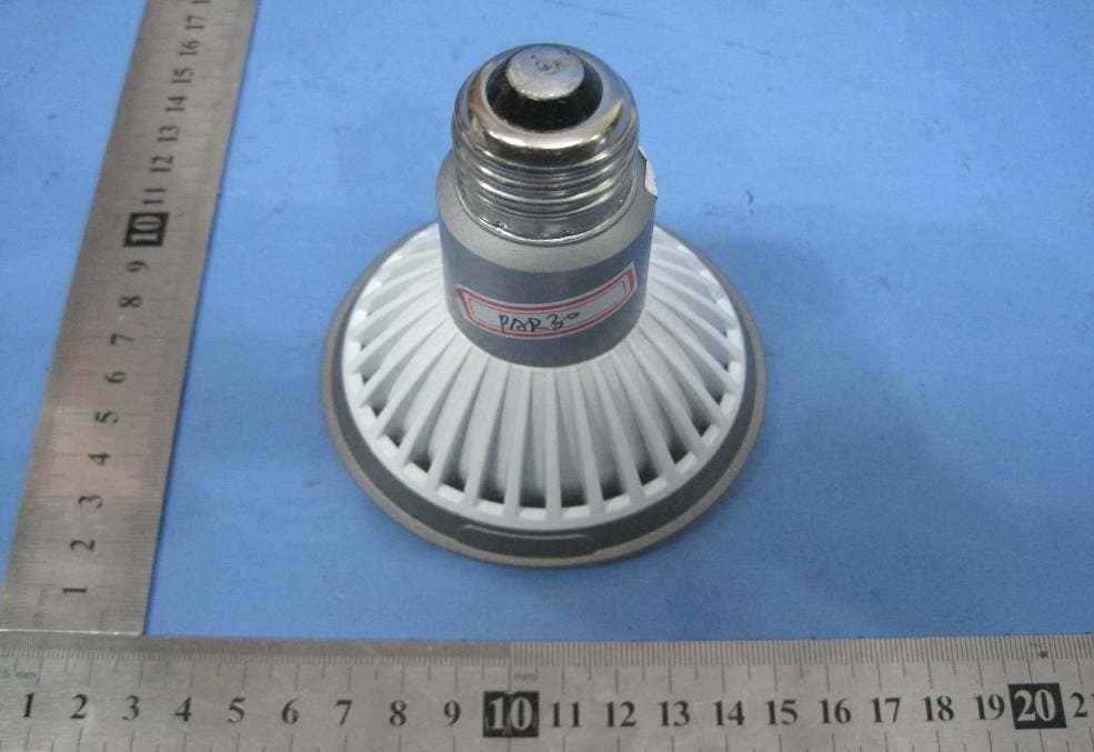
YY4-PAR38
Nov 29, 2010LED PAR LAMP
Equipment Class
8CC - Part 18 Consumer Device
YY4-HR
Nov 29, 2010LED PAR LAMP
Equipment Class
8CC - Part 18 Consumer Device