YZJREMS70WIRELESS MONITOR
Winix Inc.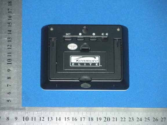
Click to zoom
Application Details
- Equipment Class
- CYY - Communications Receiver used w/Pt 15 Transmitter
- Date of Grant
- Nov 28, 2010
- Application Purpose
- Original Equipment
- Date of Application
- Nov 28, 2010
- Equipment Note
- WIRELESS MONITOR
- Frequency Range
- 433.92000000 - 433.92000000
- Company
- Winix Inc.
- Country
- South Korea
Documents & Files
Document Text
Text extracted from the exhibit documents filed with the FCC. Open a document above to read the original.
Users Manual
The remote monitoring station is a receiver wi th a receiving range of only 330 f ee t in open air wi th no obstructions. Actual receiving range will vary depending on what is in the pa th of t he signal t ransmitt ed f rom t he dehumidifier unit. Each obstruction (roof, walls, floors, ceilings, thi ck trees, etc.) wi ll effec tively cu t signal range in half. Example: The wireless remote monitor wi th a 330-foo t range is mounted on an in teri or wall or placed on a counter top so t he signal from the dehumidifier has to pa ss through one basement wall, across t he 10-foo t width of t he ro om through the room’s other wall and then through the floor to the ro om upstai rs where the receiver is located. The first wal l W IRELESS R EMOTE M ONITORING S TATION will reduce t he range t o 165 f ee t, and t he second wall will reduce t he range t o 87 f ee t. Fac tori ng in the 10-foot room, this leaves a maximum of 77 f ee t of remaining signal range. Passing up through the floor has now reduced t he effec tive range t o 38 f ee t. Typically t his allowance is enough f or most frame-constructed homes; however certain materials can reduce range even f ur ther. Metal siding, stucco, and some t ypes of glass can reduce signal range by as much as 75% compared t o t he 50% reduct ion typical of most obstructions. It is possible to receive a signal t hrough t hese materials; however maximum range will be much less, due to the ir tendency to absorb or reflect a much larger portion of the dehumidifier’s signal. NOTE: You may have t o move t he monitor closer t o t he main unit if it is no t receiving a proper signal f ollowing se t-up procedures. 10 11 Set up Guide Inser t t he ba tt eries in t he monitor. After the ba tt eries are in ser ted , t he Monitori ng St ation will st ar t re ceiving s ignal da ta f rom the dehumidifier: temperatur e, humidity, etc. should be di splayed on the monitor’s sc reen. If t hi s doesn't happen aft er 2 minutes, che ck the dehumidifier to make sure it is operating properly. Remove t he ba tt eries f rom t he monitor, wait a minute, t hen replace. Batt eri es Re cei ver On Low Batt ery Sound Ale rt Time of Day Fan On Bucket Full Pump On Temperature Humidity Wall Hanger Set Butt on Minus Plus Sou nd On/Off Classification Spec Remark Model 251.90701 Power SupplyAC 115V/60(Hz) Moisture Removal70 Pint(33.1liters)24-Hour Period Control TypeElectronic RefrigerantR410A/11.29 oz. (320g) Humidity Display Humidity Setting: 35%-70% Display Range: 20%-90% 5% Increments 1% Increments. Current Humidity. Temperature Display Display Range: Lo, 36-99°F, Hi1° F Increments. Current Temp. Display Range: Lo, 2-37°C, Hi1° C Increments. Current Temp. Timed Shut-offSetting Range: 1Hr-12Hr1 Hour Increments Fan Motor Speed2 SpeedsHigh/Low Dimensions15.74x25.59x13.6 in400x650x346mm Part #J9000003140 Net Weight49 lbs. (22.3Kg) Operating Temp.36°F-99°F Drain Pump12V DC Pump Drain Hose.25 in x 18 ft. (6.35x5,486mm) Remote Monitor2 AAA batteries PRODUCT SPECIFICATIONS ERROR CODES Error Code Error Type Possible CausesCorrective Actions E0Temperature Sensor E1Defrost Sensor E2Humidity Sensor E3Pump Drain1. Improper bucket installation. 2. Blockage to drain hose system. 3. Back flow of water through pump drain hose. 4. Improper pump drain hose installation. 5. Faulty drain pump. 1. Unplug the dehumidifier. 2. Remove the bucket. 3. Check to make sure that there is nothing blocking the c onnect ion at t he ba se of t he pump or t he bucket. 4. Reinstall the bucket, taking care that it is installed properly. 5. Check to make sure that the pump drain hose is not crimped or blocked. 6. Always allow an air gap between the end of the drain hose and where the hose will drain into. If the end of the hose becomes submerged in water, a backflow of water may occur into the machine. 7. Remove and reinstall the pump drain hose, taking care that the pump drain hose is installed properly. 8. Plug the dehumidifier in and restart 9. If the “E3” error is still indicated, please contact your nearest service center. 1. Sudden change in the surrounding temperature. 2. Faulty sensor. 1. Unplug the dehumidifier. 2. Check the surrounding area for possible reasons for sudden temperature changes. 3. Wait 30 minutes before plugging the dehumidifier back in and resuming normal operation. 4. If the “Error” is still indicated, please contact your nearest service center. 16 ADVERTENCIA CARACTERÍSTICAS PRINCIP ALES DE SU DESHUMIDIFI CADOR ASA DRENAJE DE GRAVEDAD DRENAJE DE BOMBA PARRILLA LATERAL FILTRO DE ADMISIÓN DE AIRE CUBETA RUEDECILLA PARRILLA LATERAL Mic roban ® antimicrobial technology inhibits odor- causing bacterial growth on bucket surfac e UBICACIÓN ADECUADA DEL DESHUMIDIFICADOR Utilice el deshumidificador: en un sótano para ayudar a evitar daños por humedad. en una cocina, zonas de lavadero, baños, y zonas de ejercicio que tienen humedad excesiva. para evitar daños por humedad en lugares que se guardan libros u objetos de valor. durante una construcción o remodelación para reducir el tiempo necesario para secar el muro de mampostería y pintura. APAGUE AUTOMÁTICO Cuando la cubeta está llena o no está en la posición adecuada, se encenderá la luz de advertencia de cubeta llena y se apaga la unidad automáticamente. La cubeta debe colocarse en la posición correcta para que el deshumidificador funcione. Si la cubeta no está en la posición correcta la luz permanecerá encendida y el deshumidificador no funcionará. El deshumidificador se apagará cuando se alcance el nivel de humedad fijado mas o menos 5% de la humedad relativa (RH). Para reducir el riesgo de incendio, descarga eléctrica o lesión a personas, antes de operar este electrodoméstico, lea las importantes INSTRUCCIÓNES de SEGURIDAD que se encuentran en la página 3. PANEL DE CONTROL 17 PANEL DE CONTROL Power On/Off (1) Al presionar el botón de encendido se enciende el deshumidificador “ON” y al presionarlo otra vez se apaga “OFF”. Configuración (2) Al presionar este bot…
Text truncated - open the document above for the full version.
ID Label/Location Info
FCC ID LABEL FCC ID: YZJREMS70 This device complies with Part 15 of the FCC Rules.Operation is subject to the following two conditions:1. This device may not cause harmful interference, and 2. This device must accept any interference received,including interference that may cause undesired operation. Label Location on EUT EUT Bottom View/ FCC ID Label Location
Operational Description
super‐regenerative receiver principle Figure 1 shows the typical block diagram of a super‐regenerative receiver, which consists of a matching network, an isolation amplifier, an amplifier with time varying loop gain and a bandpass feedback network forming a regenerative oscillator. Figure 1. The buffer amplifier between the antenna and the SRO (super‐regenerative oscillator) performs the following functions: It reduces the RF leakage of the oscillation signal to the antenna, it provides an input match to the antenna via the passive matching network, and it injects the RF input signal current into the oscillator tank without adding significant loading to the SRO. The time varying nature of the loop gain is designed such that the SRO transconductance periodically exceeds the critical values of the transistor transconductance gm necessary to induce instability. Consequently, the SRO periodically starts up and shuts off. The periodic shutdown of the SRO is called “quenching”.
Schematics
32 1 84 U1ALM358 56 7 U1BLM358 E1ANT C103P C12 3P L22T5 B 1 C 2 E 3 Q29018 C05P R12200K R11150RR43.9K C8 2P L31UH C9 3P R19470R Q1 9018 R610k C7 33P L13T5 R118OR R1720K R1427K C14 564 C6472 R15 4.7M R7100K R1310K R358K R165.6k R956K VDD R10100K C54P C1104 R2100K C3104 C11104 C4104 C13104 C2 104 R547K R827k D1DIODE R188.2k 123 J1CON3 11 22 33 44 D D C C B B A A Title Number Revision Size A4 Date: 2010/11/22 Sheet of File: C:\Users\..\Sheet2.Sch Drawn By: 33 34 35 36 37 38 39 40 41 42 43 44 45 46 47 48 49 50 51 19 18 17 16 15 14 13 12 11 10 9 8 7 6 5 4 3 2 1 52535455565758596061626364 32313029282726252423222120 U1QFP64L BT1BATTERY C9104 R210kR3Comment: 2.4k Q28050 R510k H_L RFCOM3 VDD R81k SW_RF RF R647K Q3NPN VDD L1L_1 MK2MICROPHONE1 X132768 C220pC720p C4103 C6104 C5104 C3104 R110k com0 com1 com2 com3 SEG0 SEG1 SEG2 SEG3 SEG4 SEG5 SEG6 SEG7 SEG8 SEG9 SEG10 SEG11 SEG12 SEG13 SEG14 SEG15 SEG16SEG17SEG18 SEG19SEG20 RF SW_RF K1 K2 K3 K4 BZ H_L BZ K1 SW K2SWK3SW S1SW SPST K1K2K3K4 Q1PNP R9RES2 C8104 1 2 3 4 5 6 7 8 9 10 11 12 13 14 15 16 17 18 19 20 21 22 23 24 25 LCDLCD VDD VCC L247uH D15818 VDD VCC J1 COM7 G+4321BZ R?0R D?2351 C?10uF C?47uF cont vout
Test Report
FCC PART 15 Subpart B EMI MEASUREMENT AND TEST REPORT For WINIX INC. 1280-10, chungwang-dong shi heung-city, Gyeonggi-Do, Korea FCC ID:YZJREMS70 November 23, 2010 This Report Concerns: Original Report Equipment Type WIRELESS MONITOR Test Engineer: Eric Li Report No.: BST10110275Y-1ER-3 Receive EUT Date/Test Date: Nov 10, 2010/Nov 10,- Nov 232010 Reviewed By: Christina Prepared By: Shenzhen BST Technology Co.,Ltd. 3F,Weames Technology Building, No. 10 Kefa Road,Science Park, Nanshan District,Shenzhen,Guangdong,China Tel: 0755-267477513 Fax: 0755-267477513 ext.826 Note: The test report is specially limited to the above company and this particular sample only. It may not be duplicated without prior written consent of Shenzhen BST Technology Co.,Ltd. This report must not be used by the client to claim product certification,approval,or endorsement by NVLAP, NIST or any agency of the US Government. WINIX INC. FCC ID: YZJREMS70 BST FCC ID REPORT : BST10110275Y-1ER-3 Page 2/15 TABLE OF CONTENTS 1. GENERAL INFORMATION .................................................................................................... 3 1.1. Report information............................................................................................................ 3 1.2. Measurement Uncertainty................................................................................................. 3 2. PRODUCT DESCRIPTION ...................................................................................................... 4 2.1. EUT Description ............................................................................................................... 4 2.2. Block Diagram of EUT Configuration ............................................................................. 4 2.3. Support Equipment List .................................................................................................... 4 2.4. Test Conditions .................................................................................................................4 3. FCC ID LABEL........................................................................................................................... 5 4. TEST RESULTS SUMMARY ................................................................................................... 6 Modifications ................................................................................................................................ 6 5. TEST EQUIPMENT USED ....................................................................................................... 7 5.1. For Conducted Emission Test ........................................................................................... 7 5.2. For Radiated Emission Measurement ............................................................................... 7 6. CONDUCTED EMISSION TEST............................................................................................. 8 6.1. Block Diagram of Test Setup............................................................................................ 8 6.2. Test Standard .................................................................................................................... 8 6.3. Conducted Emission Limit(Class B) ................................................................................ 8 6.4. EUT Configuration on Test .............................................................................................. 8 6.5. Operating Condition of EUT ............................................................................................ 8 6.6. Test Procedure ..................................................................................................................9 6.7. Test Result ........................................................................................................................ 9 7. RADIATED EMISSION MEASUREMENT ......................................................................... 10 7.1. Block Diagram of EUT Configuration ........................................................................... 10 7.2. Radiated Test Setup ........................................................................................................ 10 7.3. Test Standard ..................................................................................................................10 7.4. Radiated Emission Limit(Class B) ................................................................................. 11 7.5. EUT Configuration on Test ............................................................................................ 11 7.6. Operating Condition of EUT .......................................................................................... 11 7.7. Test Procedure ................................................................................................................ 11 7.8. Test Result ...................................................................................................................... 12 APPENDIX I ......................................................................................................................................... 13 WINIX INC. FCC ID: YZJREMS70 BST FCC ID REPORT : BST10110275Y-1ER-3 Page 3/15 1. GENERAL INFORMATION 1.1. Report information 1.1.1.This report is not a certificate of quality; it only applies to the sample of the specific product/equipment given at the time of its testing. The results are not used to indicate or imply that they are application to the similar items. In addition, such results must not be used to indicate or imply that BST approves recommends or endorses the manufacture, supplier or use of such product/equipment, or that BST in any way guarantees the later performance of the product/equipment. 1.1.2.The sample/s mentioned in this report is/are supplied by Applicant, BST therefore assumes no responsibility for the accuracy of information on the brand name, model number, origin of manufacture or any informa…
Text truncated - open the document above for the full version.
Contact Information
Applicant
Chang Mo Yang(Manager)
Test Firm
emitel (Shenzhen) LimitedLouis Lin
Technical Specifications
| # | Rule Parts | Frequency Range | Power Output |
|---|---|---|---|
| 1 | 15B | 433.92 MHz - 433.92 MHz | - |
Other Applications from Winix Inc.
YZJ25190701010
Nov 28, 2010DEHUMIDIFIER
Equipment Class
DSC - Part 15 Security/Remote Control Transmitter