YZZGAC2500Audio Conference Phone
Grandstream Networks, Inc.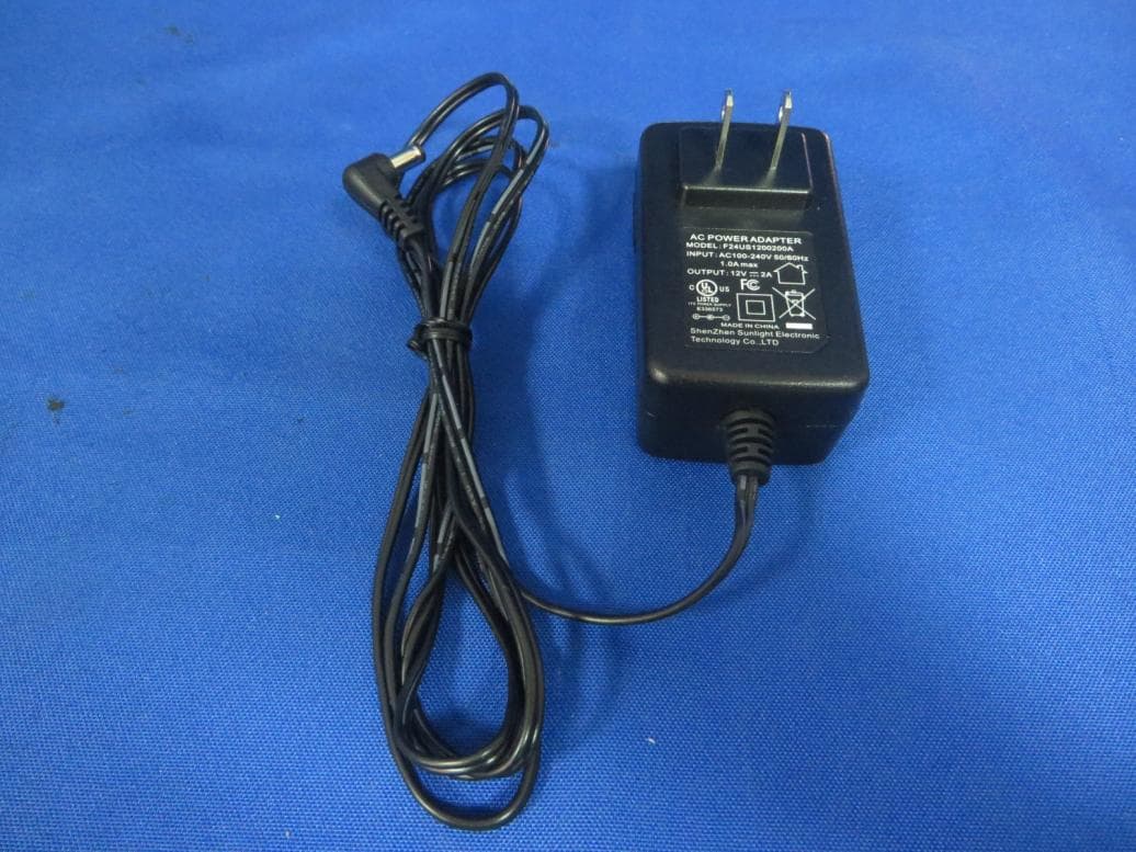
Click to zoom
Application Details
- Equipment Class
- DSS - Part 15 Spread Spectrum Transmitter
- Date of Grant
- Oct 31, 2015
- Application Purpose
- Original Equipment
- Date of Application
- Oct 31, 2015
- Equipment Note
- Audio Conference Phone
- Frequency Range
- 2402.00000000 - 2480.00000000
- Company
- Grandstream Networks, Inc.
- Country
- United States
Documents & Files
Document Text
Text extracted from the exhibit documents filed with the FCC. Open a document above to read the original.
Users Manual
Audio Conference Phone Grandstream Networks, Inc. GAC2500 Audio Conference Phone for Android TM User Guide Firmware Version 1.0.1.x GVC2500 User Guide Page 1 of 88 GAC2500 User Guide Index CHANGE LOG .............................................................................................................................................. 9 FIRMWARE VERSION 1.0.1.X .............................................................................................................. 9 WELCOME .................................................................................................................................................. 10 PRODUCT OVERVIEW .............................................................................................................................. 11 FEATURE HIGHTLIGHTS ................................................................................................................... 11 SAFETY COMPLIANCES .................................................................................................................... 12 WARRANTY ......................................................................................................................................... 12 INSTALLING GAC2500 ............................................................................................................................... 13 EQUIPMENT PACKAGE CONTENT ................................................................................................... 13 PRODUCT APPEARANCE .................................................................................................................. 13 CONNECTING GAC2500 .................................................................................................................... 14 IP MODE ....................................................................................................................................... 15 USB SLAVE MODE ...................................................................................................................... 16 DAISY CHAIN MODE ................................................................................................................... 16 MOBILE PHONE MODE .............................................................................................................. 17 GETTING TO KNOW GAC2500 ................................................................................................................. 19 DESKTOP MENU ................................................................................................................................ 19 STATUS ICONS ................................................................................................................................... 19 USING THE ONSCREEN KEYBOARD ............................................................................................... 20 ENGLISH KEYBOARD ................................................................................................................. 20 CHINESE KEYBOARD ................................................................................................................. 21 NUMBERS AND SYMBOLS ......................................................................................................... 21 USING THE LED INDICATOR ............................................................................................................. 22 ASSISTIVE TOUCH .................................................................................................................................... 23 USING TOUCHSCREEN ..................................................................................................................... 23 SHORTCUT KEYS............................................................................................................................... 23 MANAGING STATUS BAR .................................................................................................................. 24 DESKTOP MENU ................................................................................................................................ 25 EDITING WALLPAPER................................................................................................................. 25 EDIT DESKTOP............................................................................................................................ 26 ADDING AN ITEM TO DESKTOP ................................................................................................ 26 MANAGING DESKTOP APPS AND ITEMS ................................................................................. 27 OPENING AN APP ................................................................................................................ 27 MOVING AN APP .................................................................................................................. 27 REMOVING AN APP ............................................................................................................. 28 MANAFERING APPLICATIONS ............................................................................................ 29 HOME SCREEN .................................................................................................................................. 30 Firmware Version 1.0.1.x GVC2500 User Guide Page 2 of 88 CONNECTING TO NETWORK AND DEVICES ......................................................................................... 32 NETWORK ........................................................................................................................................... 32 ETHERNET .......................................................................................................................................... 32 WI-FI .................................................................................................................................................... 32 TURNING WI-FI ON OR OFF .....................…
Text truncated - open the document above for the full version.
Users Manual
Firmware Version 1.0.1.x GVC2500 User Guide Page 45 of 88 Figure 32 GAC2500 Transfer-Blind Transfer 3. Set the transfer mode to Blind .The default mode is Blind. 4. Enter the digits and press the SEND to transfer the call with user B to User C. When user C’s phone rings, the phone interface of user A is shown in figure 43. If user C answers the call, user A will automatically go back to the idle screen, which indicates the successful transfer. 5. User C’s phone will ring, the phone with CID function will display user B’s number on screen as the caller. --------------------------------------------------------------------------------------------------------------------- Note: 1. If inputted the wrong digits, press the button to delete the digit one by one, or long press the button to empty all digits. 2. Users could tap on Back icon to go back to the active call interface if wants to cancel transfer. --------------------------------------------------------------------------------------------------------------------- ATTENDED TRANSFER There are two ways of attended transfer: Call Forward and Call Transfer. Firmware Version 1.0.1.x GVC2500 User Guide Page 46 of 88 CALL TRANSFER 1. User A and user B are in an active call. 2. User A presses the button to add a new line with user C. The call with user B will be automatically put on hold. 3. User C answers the phone to set up the line with user A。 4. User A taps on More button in the menu then choose Transfer to bring up the transfer screen. The line with user B will be displayed on screen. 5. User A sets the transfer mode to Attended then choose to display user B’s number, the call will be transferred to user C. User B and user C could talk directly via the phone. Figure 33 GAC2500 Transfer-Attended Transfer CALL FORWARD 1. User A and user B are in an active call. User A tap on More button in the menu to choose Transfer to bring up the transfer screen. 2. Select the Transfer mode. As shown in figure 45. Firmware Version 1.0.1.x GVC2500 User Guide Page 47 of 88 Figure 34 GAC2500 Call Forward-Select Forward Mode 3. Input digits and then press the Send soft key. 4. Users will hear the ringback tone and see the prompt as shown in figure 46. Hang up the phone to transfer the call to the third party C automatically; press the "Cancel" button will cancel the transfer. Firmware Version 1.0.1.x GVC2500 User Guide Page 48 of 88 Figure 35 GAC2500 Call Forward-Transferring 5. User A could press the "Transfer" button to forward the call to user C. Click on "Split" button to establish line with the third patty, while user B will be put on hold. Figure 36 GAC2500 Call Forward-Split DND (DO NOT DISTURB) When DND is on, the incoming calls to the GAC2500 will be blocked without ringing. Users could see the blocked calls in call history. Once enabled, the DND icon will be displayed in the status bar on the top of the screen. 1. Hold the screen at the top of the status bar, drag and drop down to open the status bar. 2. Touch the DND iconto turn it on/off. --------------------------------------------------------------------------------------------------------------------- Note: 1. When DND is on, the active call will not be affected, all the calls after to the registered accounts will Firmware Version 1.0.1.x GVC2500 User Guide Page 49 of 88 be blocked. 2. When DND is on, the incoming calls to the GAC2500 will not be saved in the call history but in the blacklist. --------------------------------------------------------------------------------------------------------------------- MISSED CALL When there is a missed call, the missed call reminder icon call icon will be shown on the status bar and the notification bar will show the missed call. Tap on the notification to access the dial screen, or access the Call History interface to view the missed calls, the reminder icon will disappear. CALL FORWARD Call forward (Unconditional/No-answer/Busy/Time-based) can be set up on device or from web GUI. Log in GAC2500 web GUI and go to Settings page->Account->Call Settings. For details, please refer to "GAC2500 Administration Guide". SET ON LCD 1. Go to Settings->Personalized Account to select the account and access configuration page; 2. Tap on Call Forward Type to access and specify the forward type: Unconditional: Forward all calls to particular number Time based: Forward calls based on the time range. Busy: Forward calls when exists an active call. No-answer: Forward calls when phone is not answered. SET FROM WEB GUI Log in the Web GUI and go to Account->Call Settings to find Call Forward option as shown below and specifies the call forward mode in the drop-down list. Figure 37 GAC2500 Call Forward Mode On Web GUI 7-WAY CONFERENCE The GAC2500 supports up to 7-way conference. The GAC2500 can be the host to initiate a conference or join other conferences as a party. INITIATING CONFERENCE The conference can be initiated from call screen, or start conference from schedule. Firmware Version 1.0.1.x GVC2500 User Guide Page 50 of 88 The following steps introduces the way to start conference from call screen,refer to chapter Schedule for more details about initiating conference from schedule. Enter numbers in the text box or select parties from the list below. 1. Access dial screen when the phone is on idle; 2. Set call mode and select account; 3. Enter digits in the textbox; 4. Tap on the matching number on the left to add it to the textbox; Figure 38 GAC2500 Manually Add Numbers To Conference 5. Repeat the steps 3-4 to add more numbers; 6. Tap on to dial out. Press to access conference page, then tap on to add parties. 1. Access dial screen when the phone is on idle; 2. Tap on Conf button or the icon on desktop to access conference page; 3. Tap on to start adding party to conference. Firmware Version 1.0.1.x GVC2500 User Guide Page 51 of 88 Figure 39 GAC2500 Add Party To Conference 4. Enter digits and then tap on to dial out. 5. Repeat the steps 3-4 to add more par…
Text truncated - open the document above for the full version.
Cover Letter(s)
Grandstream Networks, Inc DATE : 2015/9/18 Equipment Autorisation Division Federal Communications Commission 7435 Oakland Mills Road Columbia, MD 21046 FCC ID: YZZGAC2500 Product Name: Audio Conference Phone Request for Confidentiality Pursuant to Sections 0.457 and 0.459 of the commissions rules, we hereby request that the following documents be held confidential: (List here the documents for which you are seeking confidentiality – for example ...) Schematics Block diagram Operation description These materials contain trade secrets and proprietary information and are not customarily released to the public. The public disclosure of this information might be harmful to the company and provide unjustified benefits to our competitors. Dated this 2015/9/18 By: Ning Wei Signature Printed Title: Deputy management On behalf of : Grandstream Networks, Inc Telephone: (86) 755-26014600
External Photos
1 of 5 External Photo (1) EUT Photo (2) EUT Photo (3) EUT Photo (4) EUT Photo (5) EUT Photo (6) EUT Photo (7) EUT Photo (8) EUT Photo (9) EUT Photo (10) EUT Photo
ID Label/Location Info
GAC2500 GAC2500 2015.08.05Jjsong Xbcai 2015.08.05 A-01 12V 2A 02 Label location
Internal Photos
1 of 16 Internal Photo (1) EUT Photo (2) EUT Photo (3) EUT Photo (4) EUT Photo (5) EUT Photo (6) EUT Photo (7) EUT Photo (8) EUT Photo (9) EUT Photo (10) EUT Photo (11) EUT Photo (12) EUT Photo (13) EUT Photo (14) EUT Photo (15) EUT Photo (16) EUT Photo (17) EUT Photo (18) EUT Photo (19) EUT Photo (20) EUT Photo (21) EUT Photo (22) EUT Photo (23) EUT Photo (24) EUT Photo (25) EUT Photo (26) EUT Photo (27) EUT Photo (28) EUT Photo (29) EUT Photo (30) EUT Photo (31) EUT Photo (32) EUT Photo
Test Report
MRT Technology (Suzhou) Co., Ltd Report No.: 1509RSU00304 Phone: +86-512-66308358 Report Version: V02 Fax: +86-512-66308368 Issue Date: 10-27-2015 Web: www.mrt-cert.com FCC ID: YZZGAC2500 Page Number: 1 of 98 FCC ID: YZZGAC2500 APPLICANT: Grandstream Networks, Inc. Application Type: Certification Product: Audio Conference Phone Model No.: GAC2500 Brand Name: Grandstream FCC Classification: FCC Part 15 Spread Spectrum Transmitter(DSS) FCC Rule Part(s): Part 15.247 Test Procedure(s): ANSI C63.10-2013, DA 00-705 Test Date: September 11 ~ October 09, 2015 MEASUREMENT REPORT FCC PART 15.247 Bluetooth v3.0 + HS Reviewed By : ( Robin Wu ) Approved By : ( Marlin Chen ) The test results relate only to the samples tested. This equipment has been shown to be capable of compliance with the applicable technical standards as indicated in the measurement report and was tested in accordance with the measurement procedures specified in ANSI C63.10-2013 and DA 00-705. Test results reported herein relate only to the item(s) tested. The test report shall not be reproduced except in full without the written approval of MRT Technology (Suzhou) Co., Ltd. Report No.: 1509RSU00304 FCC ID: YZZGAC2500 Page Number: 2 of 98 Revision History Report No. Version Description Issue Date 1509RSU00304 Rev. 01 Initial report 10-09-2015 1509RSU00304 Rev. 02 Update some emission data 10-27-2015 Report No.: 1509RSU00304 FCC ID: YZZGAC2500 Page Number: 3 of 98 CONTENTS Description Page 1. INTRODUCTION ..................................................................................................................... 7 1.1. Scope ........................................................................................................................... 7 1.2. MRT Test Location ....................................................................................................... 7 2. PRODUCT INFORMATION ..................................................................................................... 8 2.1. Equipment Description .................................................................................................. 8 2.2. Product Specification Subjective to this Standard ......................................................... 8 2.3. Operation Frequency / Channel List ............................................................................. 9 2.4. Pseudorandom Frequency Hopping Sequence ........................................................... 10 2.5. Device Capabilities ..................................................................................................... 10 2.6. Test Configuration ...................................................................................................... 10 2.7. Test Software ............................................................................................................. 10 2.8. EMI Suppression Device(s)/Modifications ................................................................... 10 2.9. Labeling Requirements ................................................................................................ 11 3. DESCRIPTION of TEST ........................................................................................................ 12 3.1. Evaluation Procedure ................................................................................................. 12 3.2. AC Line Conducted Emissions ................................................................................... 12 3.3. Radiated Emissions .................................................................................................... 13 4. ANTENNA REQUIREMENTS ................................................................................................ 14 5. TEST EQUIPMENT CALIBRATION DATE ............................................................................ 15 6. MEASUREMENT UNCERTAINTY ......................................................................................... 16 7. TEST RESULT ...................................................................................................................... 17 7.1. Summary .................................................................................................................... 17 7.2. 20dB Bandwidth Measurement ................................................................................... 18 7.2.1. Test Limit ................................................................................................................ 18 7.2.2. Test Procedure used ............................................................................................... 18 7.2.3. Test Setting ............................................................................................................. 18 7.2.4. Te s t S e t u p ............................................................................................................... 19 7.2.5. Test Result .............................................................................................................. 20 7.3. Output Power Measurement ....................................................................................... 23 7.3.1. Test Limit ................................................................................................................ 23 7.3.2. Test Procedure Used .............................................................................................. 23 7.3.3. Test Setting ............................................................................................................. 23 7.3.4. Te s t S e t u p ............................................................................................................... 24 Report No.: 1509RSU00304 FCC ID: YZZGAC2500 Page Number: 4 of 98 7.3.5. Test Result .............................................................................................................. 25 7.4. Carrier Frequency Separation Measurement .............................................................. 29 7.4.1. Test Li…
Text truncated - open the document above for the full version.
Test Report
Report No.: 1509RSU00304 FCC ID: YZZGAC2500 Page Number: 31 of 98 DH5 Carrier Frequency Separation Channel 00 (2402MHz) Channel 39 (2441MHz) Channel 78 (2480MHz) Report No.: 1509RSU00304 FCC ID: YZZGAC2500 Page Number: 32 of 98 2DH5 Carrier Frequency Separation Channel 00 (2402MHz) Channel 39 (2441MHz) Channel 78 (2480MHz) Report No.: 1509RSU00304 FCC ID: YZZGAC2500 Page Number: 33 of 98 3DH5 Carrier Frequency Separation Channel 00 (2402MHz) Channel 39 (2441MHz) Channel 78 (2480MHz) Report No.: 1509RSU00304 FCC ID: YZZGAC2500 Page Number: 34 of 98 7.5. Number of Hopping Channels Measurement 7.5.1. Test Limit This frequency hopping system must employ a minimum of 15 hopping channels. 7.5.2. Test Procedure Used ANSI C63.10-2013 - Section 7.8.3 7.5.3. Test Settitng 1. Span = the frequency band of operation. 2. RBW ≥ 1 % of the span 3. VBW ≥ RBW 4. Detector = Peak 5. Trace mode = max hold 6. Sweep time = auto couple 7. The trace was allowed to stabilize 7.5.4. Test Setup Report No.: 1509RSU00304 FCC ID: YZZGAC2500 Page Number: 35 of 98 7.5.5. Test Result Te s t Mo d e (Hopping) Channel Numbers Frequency (MHz) Limit (Hopping Channels) Result DH5 79 2402~2480 ≥ 15 Pass 2DH5 79 2402~2480 ≥ 15 Pass 3DH5 79 2402~2480 ≥ 15 Pass DH5 Number of Hopping Channels 2402 ~ 2421MHz 2422 ~ 2441MHz 2442 ~ 2461MHz 2462 ~ 2480MHz Report No.: 1509RSU00304 FCC ID: YZZGAC2500 Page Number: 36 of 98 2DH5 Number of Hopping Channels 2402 ~ 2421MHz 2422 ~ 2441MHz 2442 ~ 2461MHz 2462 ~ 2480MHz Report No.: 1509RSU00304 FCC ID: YZZGAC2500 Page Number: 37 of 98 3DH5 Number of Hopping Channels 2402 ~ 2421MHz 2422 ~ 2441MHz 2442 ~ 2461MHz 2462 ~ 2480MHz Report No.: 1509RSU00304 FCC ID: YZZGAC2500 Page Number: 38 of 98 7.6. Time of Occupancy Measurement 7.6.1. Test Limit The maximum permissible time of occupancy is 400ms within a period of 400ms multiplied by the number of hopping channels employed. 7.6.2. Test Procedure Used ANSI C63.10-2013 - Section 7.8.4 7.6.3. Test Settitng 1. Span = zero span, centered on a hopping channel. 2. RBW = 1MHz 3. VBW ≥ RBW 4. Sweep time = as necessary to capture the entire dwell time per hopping channel 5. Detector = Peak 6. Trace mode = max hold If possible, use the marker-delta function to determine the dwell time. If this value varies with different modes of operation (data rate, modulation format, etc.), repeat this test for each variation. An oscilloscope may be used instead of a spectrum analyzer. The EUT shall show compliance with the appropriate regulatory limit for the number of hopping channels. A plot of the data shall be included in the test report. Report No.: 1509RSU00304 FCC ID: YZZGAC2500 Page Number: 39 of 98 7.6.4. Test Setup Report No.: 1509RSU00304 FCC ID: YZZGAC2500 Page Number: 40 of 98 7.6.5. Test Result Te s t Mo d e Channel No. Frequency (MHz) Time of Occupancy (ms) Limit (ms) Result 3DH1 39 2441 60.80 < 400 Pass 3DH3 39 2441 32.00 < 400 Pass 3DH5 39 2441 21.84 < 400 Pass 3DH1 Time of Occupancy Channel 39(2441MHz) Channel 39(2441MHz) Note: Test Time Period: 0.4*79=31.6sec, Hopping Times Within 1sec: 40/50msec=800 hops/sec. The Maximum Occupancy Time within 31.6sec: [(0.190ms*800)/79]*31.6 =60.80 msec. 3DH3 Time of Occupancy Channel 39(2441MHz) Channel 39(2441MHz) Note: Test Time Period: 0.4*79=31.6sec, Hopping Times Within 1sec: 20/50msec=400hops/sec. The Maximum Occupancy Time within 31.6sec: [(0.200ms*400)/79]*31.6 =32.00 msec. Report No.: 1509RSU00304 FCC ID: YZZGAC2500 Page Number: 41 of 98 3DH5 Time of Occupancy Channel 39(2441MHz) Channel 39(2441MHz) Note: Test Time Period: 0.4*79=31.6sec, Hopping Times Within 1sec: 13/50msec=260 hops/sec. The Maximum Occupancy Time within 31.6sec: [(0.210ms*260)/79]*31.6 =21.84 msec. Report No.: 1509RSU00304 FCC ID: YZZGAC2500 Page Number: 42 of 98 7.7. Band-edge Compliance Measurement 7.7.1. Test Limit The maximum permissible emission level is 20dBc. Any emissions were lying outside of the emission bandwidth and in authorized band edges to a field strength limit specified in Section 15.209 of the Title 47 CFR. 7.7.2. Test Procedure Used ANSI C63.10-2013 - Section 6.10.4 7.7.3. Test Setting 1. Span = wide enough to capture the peak level of the emission operating on the channel closest to the band edge, as well as any modulation products which fall outside of the authorized band of operation. 2. RBW ≥ 1% of spectrum analyzer display span 3. VBW ≥ RBW 4. Detector = peak 5. Sweep time = auto couple 6. Trace mode = max hold 7. Trace was allowed to stabilize Allow the trace to stabilize. Set the marker on the emission at the band edge, or on the highest modulation product outside of the band, if this level is greater than that at the band edge. Enable the marker-delta function, than use the marker-to-peak function to move the marker to the peak of the in-band emission. =100kHz
Test Report
Report No.: 1509RSU00304 FCC ID: YZZGAC2500 Page Number: 43 of 98 7.7.4. Test Setup Report No.: 1509RSU00304 FCC ID: YZZGAC2500 Page Number: 44 of 98 7.7.5. Test Result Te s t Mo d e Channel No. Frequency (MHz) Limit Result DH5 00 2402 20dBc Pass DH5 78 2480 20dBc Pass 2DH5 00 2402 20dBc Pass 2DH5 78 2480 20dBc Pass 3DH5 00 2402 20dBc Pass 3DH5 78 2480 20dBc Pass DH5 Band-edge Compliance Channel 00 (2402MHz) Channel 78 (2480MHz) 2DH5 Band-edge Compliance Channel 00 (2402MHz) Channel 78 (2480MHz) Report No.: 1509RSU00304 FCC ID: YZZGAC2500 Page Number: 45 of 98 3DH5 Band-edge Compliance Channel 00 (2402MHz) Channel 78 (2480MHz) DH5 Operation Frequency Range of 20dB Bandwidth within Hopping Mode Channel 00 (2402MHz) Channel 78 (2480MHz) 2DH5 Operation Frequency Range of 20dB Bandwidth within Hopping Mode Channel 00 (2402MHz) Channel 78 (2480MHz) Report No.: 1509RSU00304 FCC ID: YZZGAC2500 Page Number: 46 of 98 3DH5 Operation Frequency Range of 20dB Bandwidth within Hopping Mode Channel 00 (2402MHz) Channel 78 (2480MHz) Report No.: 1509RSU00304 FCC ID: YZZGAC2500 Page Number: 47 of 98 7.8. Conducted Spurious Emissions Measurement 7.8.1. Test Limit In any 100 kHz bandwidth outside the frequency band in which the spread spectrum or digitally modulated intentional radiator is operating, the radio frequency power that is produced by the intentional radiator shall be at least 20 dB below that in the 100 kHz bandwidth within the band that contains the highest level of the desired power, based on either an RF conducted or a radiated measurement, provided the transmitter demonstrates compliance with the peak conducted or a radiated measurement, provided the transmitter demonstrates compliance with the peak conducted power limits. If the transmitter complies with the conducted power limits based on the use of RMS averaging over a time interval, the attenuation required under this paragraph shall be 30 dB instead of 20 dB. 7.8.2. Test Procedure Used ANSI C63.10-2013 - Section 7.8.8 7.8.3. Test Setting 1. Span = wide enough to capture the peak level of the in-band emission and all spurious emissions (e.g., harmonics) from the lowest frequency generated in the EUT up through the 10 th harmonic. Typically, several plots are required to cover this entire span. 2. RBW = 100 KHz 3. VBW ≥ RBW 4. Detector = peak 5. Sweep time = auto couple 6. Trace mode = max hold 7. Trace was allowed to stabilize Set the marker on the peak of any spurious emission recorded. The level displayed must comply with the limit specified in this section. Report No.: 1509RSU00304 FCC ID: YZZGAC2500 Page Number: 48 of 98 7.8.4. Test Setup Report No.: 1509RSU00304 FCC ID: YZZGAC2500 Page Number: 49 of 98 7.8.5. Test Result Te s t Mo d e Channel No. Frequency (MHz) Limit (MHz) Result DH5 00 2402 20dBc Pass DH5 39 2441 20dBc Pass DH5 78 2480 20dBc Pass 2DH5 00 2402 20dBc Pass 2DH5 39 2441 20dBc Pass 2DH5 78 2480 20dBc Pass 3DH5 00 2402 20dBc Pass 3DH5 39 2441 20dBc Pass 3DH5 78 2480 20dBc Pass DH5 Conducted Spurious Emissions Channel 00 (2402MHz) Channel 39 (2441MHz) Channel 78 (2480MHz) Report No.: 1509RSU00304 FCC ID: YZZGAC2500 Page Number: 50 of 98 2DH5 Conducted Spurious Emissions Channel 00 (2402MHz) Channel 39 (2441MHz) Channel 78 (2480MHz) Report No.: 1509RSU00304 FCC ID: YZZGAC2500 Page Number: 51 of 98 3DH5 Conducted Spurious Emissions Channel 00 (2402MHz) Channel 39 (2441MHz) Channel 78 (2480MHz) Report No.: 1509RSU00304 FCC ID: YZZGAC2500 Page Number: 52 of 98 7.9. Radiated Spurious Emission Measurement 7.9.1. Test Limit All out of band emissions appearing in a restricted band as specified in Section 15.205 of the Title 47 CFR must not exceed the limits shown in Table per Section 15.209. FCC Part 15 Subpart C Paragraph 15.209 Frequency [MHz] Field Strength [V/m] Measured Distance [Meters] 0.009 - 0.490 2400/F (kHz) 300 0.490 - 1.705 24000/F (kHz) 30 1.705 – 30 30 30 30 – 88 100 3 88 – 216 150 3 216 – 960 200 3 Above 960 500 3 7.9.2. Test Procedure Used ANSI C63.10-2013 - Section 11.12.1 7.9.3. Test Setting Peak Field Strength Measurements 1. Analyzer center frequency was set to the frequency of the radiated spurious emission of interest 2. RBW = as specified in Table 1 3. VBW = 3 * RBW 4. Detector = peak 5. Sweep time = auto couple 6. Trace mode = max hold 7. Trace was allowed to stabilize Report No.: 1509RSU00304 FCC ID: YZZGAC2500 Page Number: 53 of 98 Table 1 - RBW as a function of frequency Frequency RBW 9 ~ 150 kHz 200 ~ 300 Hz 0.15 ~ 30 MHz 9 ~ 10 kHz 30 ~ 1000 MHz 100 ~ 120 kHz > 1000 MHz 1 MHz Average Field Strength Measurements 1. Analyzer center frequency was set to the frequency of the radiated spurious emission of interest 2. RBW = 1MHz 3. VBW ≥ 1/T 4. De As an alternative, the instrument may be set to linear detector mode. Ensure that video filtering is applied in linear voltage domain (rather than in a log or dB domain). Some instruments require linear display mode in order to accomplish this. Others have a setting for Average-VBW Type, which can be set to “Voltage” regardless of the display mode 5. Detector = Peak 6. Sweep time = auto 7. Trace mode = max hold 8. Allow max hold to run for at least 50 times (1/duty cycle) traces Report No.: 1509RSU00304 FCC ID: YZZGAC2500 Page Number: 54 of 98 7.9.4. Test Setup 9kHz ~ 30MHz Test Setup : 30MHz ~ 1GHz Test Setup: Report No.: 1509RSU00304 FCC ID: YZZGAC2500 Page Number: 55 of 98 1GHz ~ 18GHz Test Setup: 18GHz ~25GHz Test Setup: Report No.: 1509RSU00304 FCC ID: YZZGAC2500 Page Number: 56 of 98 7.9.5. Test Result Test Mode: …
Text truncated - open the document above for the full version.
Contact Information
Applicant
Ning Wei
Test Firm
MRT Technology (Suzhou) Co., LtdWu Jian
[email protected]86-512-66308358
Technical Specifications
| # | Rule Parts | Frequency Range | Power Output |
|---|---|---|---|
| 1 | 15C | 2.40 GHz - 2.48 GHz | 578.00 µW |
Other Applications from Grandstream Networks, Inc.
YZZGWN7712P
Sep 04, 2026Layer 2 Lite Managed Network PoE Switch
Equipment Class
JAD - Part 15 Class A Digital DeviceYZZGWN7801PC
Aug 27, 2026Enterprise Layer 2+ Compact Managed Switch
Equipment Class
JAD - Part 15 Class A Digital DeviceYZZGWN7823P
Aug 26, 2026Layer 3 Multi-Gigabit Network Switch
Equipment Class
JAD - Part 15 Class A Digital DeviceYZZGWN7703P
Aug 26, 202624 Unmanaged Gigabit Port and 2 SFP Port Switch with 24 PoE+
Equipment Class
JAD - Part 15 Class A Digital DeviceYZZGWN7673
Jul 29, 2026Dual-Band Wi-Fi 7 Access Point
Equipment Class
DTS - Digital Transmission System