YZZGWN7660802.11ax 2x2 Wi-Fi 6 Access Point
Grandstream Networks, Inc.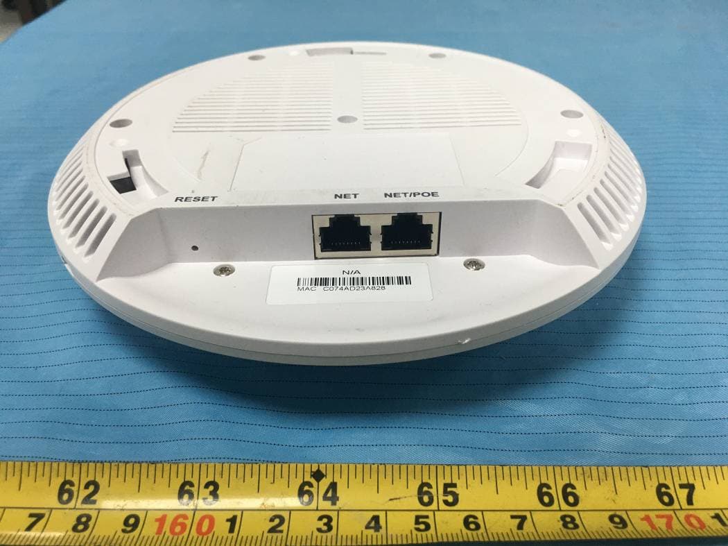
Click to zoom
Application Details
- Equipment Class
- DTS - Digital Transmission System
- Date of Grant
- Mar 16, 2021
- Application Purpose
- Original Equipment
- Date of Application
- Mar 16, 2021
- Equipment Note
- 802.11ax 2x2 Wi-Fi 6 Access Point
- Frequency Range
- 2412.00000000 - 2462.00000000
- Company
- Grandstream Networks, Inc.
- Country
- United States
Documents & Files
Document Text
Text extracted from the exhibit documents filed with the FCC. Open a document above to read the original.
Users Manual
For Certification, Warranty and RMA information, please visit www.grandstream.com Grandstream Networks, Inc. 126 Brookline Ave, 3rd Floor Boston, MA 02215. USA Tel : +1 (617) 566 - 9300 Fax: +1 (617) 249 - 1987 www.grandstream.com GWN7660 802.11ax 2x2:2 Wi-Fi 6 Access Point Quick Installation Guide Content English.................................................................................1 简体中文............................................................................7 Español..............................................................................13 Français..............................................................................19 Deutsch..............................................................................25 Italiano...............................................................................31 Polski................................................................................ 37 Português.......................................................................... 43 Русскй...............................................................................49 ~1~ ~2~ OVERVIEW The GWN7660 is a high-efficiency, enterprise-grade 802.11ax Wi-Fi 6 access point, ideal for small-to-medium sized businesses, multiple floor buildings, residential settings and commercial locations. It offers dual- band 2x2:2 MU-MIMO with DL/UL OFDMA technology and a sophisti- cated antenna design for maximum network throughput and expanded Wi-Fi coverage range. To ensure easy installation and management, the GWN7660 uses a controller-less distributed network management design in which the controller is embedded within the product’s Web user interface. The GWN7660 is also supported by GWN.Cloud and GWN Manager, Grandstream’s cloud and on-premise Wi-Fi manage- ment platform. It is the ideal Wi-Fi AP for voice-over-Wi-Fi deployments and offers a seamless connection with Grandstream’s Wi-Fi capable IP phones. With support for advanced QoS, low-latency real-time ap- plications, mesh networks, captive portals, 256 concurrent clients per AP and dual Gigabit network ports with PoE/PoE+, GWN7660 is an ideal Wi-Fi access point for medium wireless network deployments with medium-to-high user density. PACKAGE CONTENTS GWN7660 PORTS POWERING AND CONNECTING THE GWN7660 PRECAUTIONS •Do not attempt to open, disassemble, or modify the device. •Do not expose this device to temperatures outside range of 0 °C to 45 °C for operating and -10 °C to 60 °C for storage. •Do not expose the GWN7660 to environments outside of the following humid- ity range: 10-90% RH (non-condensing). •Do not power cycle your GWN7660 during system boot up or firmware up- grade. You may corrupt firmware images and cause the unit to malfunction. GWN7660 can be powered on using PoE/PoE+ switch using following steps: Step 1: Plug a RJ45 Ethernet cable into the network port of GWN7660. EN 1x GWN7660 Access Point 1x Mounting Bracket 1x Ceiling Mounting Bracket 3x Screw (PM 3 x 50) 3x Screw (PA 3.5 x 20) 3x Plastic Expansion Bolt PortDescription NET/POEEthernet RJ45 port (10/100/1000Mbps) supporting PoE/PoE+. NETEthernet RJ45 port (10/100/1000Mbps) to your rout- er or another GWN76xx. RESETFactory reset button. Press for 7 seconds to reset factory default settings. Network Port RJ45 Ethernet Cable to power over Ethernet (PoE/PoE+) Switch 1 x Quick Installation Guide 3x M3 NUT Step 2: Plug the other end into the uplink port of the power over Ethernet (PoE/PoE+) switch. HARDWARE INSTALLATION GWN7660 can be mounted on the wall or ceiling, Please refer to the following steps for the appropriate installation. ~3~ ~4~ Ceiling Mount 1.Position the mounting bracket at the desired location on the wall with the arrow pointing up. 2.Use a pencil to mark the four mounting holes (screw holes DIA 5.5mm, reticle hole DIA 25mm). 3.If your Ethernet cable feeds through the wall, then cut or drill a circle approximately 18mm in diameter. 4.Insert screw anchors into the 5.5mm holes. Attach the mounting bracket to the wall by inserting the screws into the anchors. 1.Remove the ceiling tile. 2.Place the ceiling backing plate in the center of the ceiling tile and mark the mounting screw holes (screw holes DIA 5.5mm, reticle hole DIA 25mm). 3.Insert the screws through the mounting bracket. 1 2 3 4 5 1 2 3 6 M3.0x50 screw M3 nut Ceiling Mounting Note: Ceiling mounting is recommended for optimal coverage perfor- mance. Wall PA3.5x20 Screw Plastic Expan- sion Bolt Wall Mount 4 5 6 5.Connect the ethernet cable (RJ45) to the correct ports of your GWN7660. 6.Align the arrow on the GWN7660 AP with the arrow on the locking tab of the mounting bracket and ensure that your GWN is firmly seated on the mounting bracket. 7.Turn the GWN clockwise until it locks into place and fits the locking tab. 4.Connect th Ethernet cable (RJ45) to the correct ports of your GWN7660. 5.Align the arrow on the GWN7660 with the arrow on the locking tab of the mounting bracket and ensure that your GWN is firmly seated on the mounting bracket and connect the network and power cables. 6.Turn the GWN clockwise until it locks into place and fits the locking tab. ~5~ ~6~ CONNECT TO GWN7660 DEFAULT Wi-Fi NETWORK GWN7660 can be used as standalone access point out of box, or after factory reset with Wi-Fi enabled by default. After powering the GWN7660 and connecting it to the network, GWN7660 will broadcast a default SSID based on its MAC address GWN[MAC’s last 6 digits] and a random password. Note: GWN7660’s default SSID and password information are printed on the MAC tag of the unit. A computer connected to the GWN7660’s SSID, or to the same network as the GWN7660 can discover and access its configuration interface us- ing one of the below methods: Method 1: Discover GWN7660 using its MAC Address 1.Locate the MAC address on the MAC tag of the unit, which is on the underside of the device, or on the package. 2.From a computer connected to same network as the GWN7660, type in following address using GWN7660…
Text truncated - open the document above for the full version.
Users Manual
~27~ ~28~ 1. Positionieren der Halterung an der gewünschten Stelle mit dem Richtungspfeil nach oben. 2. Markieren der Montagelöcher mit einem Stift. (Lochdurchmesser 5,5mm, Lochkreisradius 25mm). 3. Bohren Sie bitte ein Loch mit einen Durchmesser von ca. 18mm, um das Ethernetkabel durch eine Wand zu führen. 4. Stecken Sie die Montagedübel in die gebohrten 5,5mm Löcher. Halten Sie die Halterung über die Montagelöcher, stecken Sie die Schrauben in die Dübel und ziehen Sie diese fest. 1 3 2 Deckenmontage Bemerkung: Wir empfehlen das Produkt an der Decke zu montieren, um eine optimale Leistung und Ausleuchtung zu erzielen. 1. Nehmen Sie die Deckenplatte heraus. 2. Platzieren Sie den Access-Point in der Plattenmitte und markieren Sie die Montagelöcher mit einem Stift. (Lochdurchmesser 5,5mm, Lochkreisradius 25mm). 3. Befestigen Sie die Halterung mit den beiliegenden Schrauben. 4 6 5 5. Stecken Sie das Ethernet-Kabel (RJ45) in den Netzwerk-Port des GWN7660. 5. Zur Montage des GWN7660AP muss der Richtungspfeil am Access-Point mit dem Richtungspfeil an der montierten Halterung übereinstimmen, die Geräte passen nur so korrekt zusammen. 6. Drehen Sie nun den GWN Access-Point im Uhrzeigersinn bis dieser fest in der Halterung sitzt. 1 2 3 Halterung für die Deckenmontage Schraube M3 x 50 Wand Schraube (PA 3.5X20) Abstandstüllen M3 Muttern Wandmontage 4 5 6 4. Stecken Sie das Ethernet-Kabel (RJ45) in den Netzwerk-Port des GWN7660. 5. Zur Montage des GWN7660AP muss der Richtungspfeil am Access-Point mit dem Richtungspfeil an der montierten Halterung übereinstimmen, die Geräte passen nur so korrekt zusammen. 6. Drehen Sie nun den GWN Access-Point im Uhrzeigersinn bis dieser fest in der Halterung sitzt. ~29~ ~30~ VERBINDEN SIE SICH MIT DEM VOREIN- GESTELLTEN Wi-Fi-NETZWERK DES GWN7660 Der GWN7660 kann als “Stand-alone” Access-Point direkt verwendet werden - oder nach einem Reset auf Werkseinstellungen - Wi-Fi ist in der Grundeinstellung immer aktiviert. Sobald der GWN7660 mit Strom versorgt und an das Netzwerk ange- schlossen ist, sendet der Access-Point eine voreingestellte SSID, diese basiert auf der MAC Adresse des Gerätes (die letzten sechs Ziffern/Bu- chstaben der MAC Adresse) sowie einem Zufallspasswort. HINWEIS: Die SSID und Passwortinformationen befinden sich auf dem MAC-Adressen Aufkleber auf der Rückseite des Gerätes. ZUGANG ZUR KONFIGURATIONSSCHNITTSTELLE Sobald ein Computer zur SSID des GWN7660 oder im selben Netzwerk angeschlossen ist, kann nach ihm gesucht werden um so zur Konfigura- tionsschnittstelle zu gelangen: Methode 1: Suche nach dem GWN7660 via MAC Adresse 1.Die MAC-Adresse des Gerätes befindet sich entweder auch dem Aufkleber auf der Unterseite des Gerätes, oder auf dem Aufkleber an der Verpackung. 2.Nutzen Sie einen Computer im selben Netzwerk wie der GWN7660 geben Sie die MAC Adresse in den Internetbrowser ein, nutzen Sie bitte nur dieses Format: https://gwn_<mac>.local Beispiel: Lautet die MAC Adresse des GWN7660 z.B. C0:74:AD:8B:4E:28 dann tippen Sie diese bitte wie folgt in die Adresszeile des Browsers: https://gwn_c074ad8b4e28.local Methode 2: Suche nach dem GWN7660 via GWNDiscovery- Tool 1.Laden Sie das GWNDiscoveryTool von der Grandstream Support- Website: http://www.grandstream.com/tools/GWNDiscoveryTool.zip 2.Öffnen Sie das GWNDiscoveryTool und klicken Sie auf Scan. 3.Das Tool (Werkzeug) wird alle im Netz installierten GWN7660 Ac- cess-Points finden und deren MAC Adresse sowie die jeweilige IP Adresse anzeigen. 4.Klicken Sie auf Manage Device (Gerät verwalten) um direkt auf die Konfigurationsseite des GWN7660 zu gelangen oder tippen Sie ein- fach die angezeigte IP Adresse in die Adresszeile des Browsers. Bemerkung: •Stellen Sie sicher, dass der GWN7660 nicht schon einem anderen GMN7660 oder einem GWN7000 Router zugeordnet (Paired) ist, da sich ansonsten das Konfigurationsfenster nicht öffnen lässt. •Ist der GWN7660 bereits zugeordnet, lösen Sie diese Zuordnung oder setzen Sie den Access Point auf Werkseinstellungen zurück. •Für die Einhaltung der im jeweiligen Anwendungsland gültigen Reg- ularien für Frequenzen, Übertragungsbandbreite, Sendeleistung usw. ist der Anwender verantwortlich. •Um einen oder mehrere GWN7660 über die Cloud zu verwalten, wechseln Sie bitte zu https://www.gwn.cloud Das ausführliche Benutzerhandbuch kann geladen werden von: http://www.grandstream.com/our-products Geben Sie Benutzername und Passwort ein. Der voreingestellte Admin- istrator-Benutzername lautet “admin”, das Zufallspasswort befindet sich auf dem Produktaufkleber auf der Rückseite der GWN7660. Die GNU GPL Lizenz ist in der Gerätesoftware hinterlegt und kann über die Web-Schnittstelle unter my_device_ip/gpl_license (Endgerät_ip/gpl_Lizenz aufgerufen werden. Die Lizenz ist ebenfalls abrufbar unter http://www.grand- stream.com/legal/open-source-software. Um eine CD mit der Lizenz zu er- halten, senden Sie uns bitte eine Email an [email protected]. ~31~ ~32~ PANORAMICA . Il GWN7660 è un punto di accesso 6 Wi-Fi 802.11ax di livello aziendale ad alta efficienza, ideale per aziende di piccole e medie dimensioni, edi- fici a più piani, ambienti residenziali e sedi commerciali. Offre 2x2:2 MU- MIMO dual-band con tecnologia DL/UL OFDMA e un sofisticato design di antenna per capacità di rete massima e gamma di copertura Wi-Fi estesa. Per assicurare qualsiasi installazione e gestione, il GWN7660 usa design di gestione di rete distribuito senza centralina in cui la centralina è nas- costa nell’interfaccia utente Web del prodotto. Il GWN7660 è supportato anche da GWN.Cloud e GWN Manager, la piattaforma di gestione Wi-Fi cloud e in locale di Grandstream. È l’AP Wi-Fi ideale per l’installazione di sistemi con tecnologia Wi-Fi voice-over e offre una connessione perfetta per i telefoni IP Grandstream con Wi-Fi. Con supporto per QoS avanzato, applicazioni in tempo reale a bassa latenza, reti mesh, captive portal, 256 dispositivi client contemporanei per AP e porte di rete Gigabit doppie con PoE/PoE+, il…
Text truncated - open the document above for the full version.
Cover Letter(s)
Grandstream Networks, Inc. 126 Brookline Ave, 3rd Floor Boston, MA 02215, USA Tel: 1-617-5669300 Fax: 1-617-2491987 Email: [email protected] FCC Confidential Authorization Date: 2021-2-27 FEDERAL COMMUNICATIONS COMMISSIONS Authorization and Evaluation Division 7435 Oakland Mills Road Columbia, MD 21046 Subject: Confidentiality Request regarding application for certification of FCC ID: YZZGWN7660 In accordance with Sections 0.457 and 0.459 of the Commission’s Rules, Grandstream Networks, Inc. hereby requests long-term confidential treatment of information accompanying this application as outlined below: Block Diagram Schematics Operation Description Parts List The above materials contain proprietary and confidential information not customarily released to the public. The public disclosure of these materials provides unjustified benefits to its competitors in the market. Sincerely Yours, Signature: Ning Wei Manager
External Photos
Bay Area Compliance Laboratories Corp. (Shenzhen) Project No.: RSZ201228006-RF Page 1 of 4 EXHIBIT B - EUT EXTERNAL PHOTOGRAPHS Bay Area Compliance Laboratories Corp. (Shenzhen) Project No.: RSZ201228006-RF Page 2 of 4 Bay Area Compliance Laboratories Corp. (Shenzhen) Project No.: RSZ201228006-RF Page 3 of 4 Bay Area Compliance Laboratories Corp. (Shenzhen) Project No.: RSZ201228006-RF Page 4 of 4
ID Label/Location Info
Bay Area Compliance Laboratories Corp. (Shenzhen) Project No.: RSZ201228006-RF EXHIBIT A - FCC ID LABEL AND LOCATION FCC ID Label FCC ID Label Location Information The label shown shall be permanently affixed at a conspicuous location on the device and be readily visible to the user at the time purchase (Labeling requirements per 2.925)
Internal Photos
Bay Area Compliance Laboratories Corp. (Shenzhen) Project No.: RSZ201228006-RF Page 1 of 5 EXHIBIT C - EUT INTERNAL PHOTOGRAPHS Bay Area Compliance Laboratories Corp. (Shenzhen) Project No.: RSZ201228006-RF Page 2 of 5 Bay Area Compliance Laboratories Corp. (Shenzhen) Project No.: RSZ201228006-RF Page 3 of 5 Bay Area Compliance Laboratories Corp. (Shenzhen) Project No.: RSZ201228006-RF Page 4 of 5 Bay Area Compliance Laboratories Corp. (Shenzhen) Project No.: RSZ201228006-RF Page 5 of 5 2.4GHz ant 1 2.4GHz ant 2 5GHz ant 1 5GHz ant 2
RF Exposure Info
Bay Area Compliance Laboratories Corp. (Shenzhen) Report No.: RSZ201228006-00A FCC Part 15.247 Page 10 of 78 FCC §15.247 (i) & §2.1091- MAXIMUM PERMISSIBLE EXPOSURE (MPE) Applicable Standard According to subpart 15.247 (i) and subpart 2.1091 systems operating under the provisions of this section shall be operated in a manner that ensures the public is not exposed to RF energy level in excess of the communication guidelines. Limits for General Population/Uncontrolled Exposure Limits for General Population/Uncontrolled Exposure Frequency Range (MHz) Electric Field Strength (V/m) Magnetic Field Strength (A/m) Power Density (mW/cm 2 ) Averaging Time (Minutes) 0.3-1.34 614 1.63 *(100) 30 1.34-30 824/f 2.19/f *(180/f 2 ) 30 30-300 27.5 0.073 0.2 30 300-1500 / / f/1500 30 1500-100,000 / / 1.0 30 f = frequency in MHz * = Plane-wave equivalent power density Result Calculated Formulary: Predication of MPE limit at a given distance S = 2 4R PG S = power density (in appropriate units, e.g. mW/cm2) P = power input to the antenna (in appropriate units, e.g., mW). G = power gain of the antenna in the direction of interest relative to an isotropic radiator, the power gain factor, is normally numeric gain. R = distance to the center of radiation of the antenna (appropriate units, e.g., cm) Bay Area Compliance Laboratories Corp. (Shenzhen) Report No.: RSZ201228006-00A FCC Part 15.247 Page 11 of 78 Frequency (MHz) Antenna Gain Tune up conducted power Evaluation Distance (cm) Power Density (mW/cm 2 ) MPE Limit (mW/cm 2 ) (dBi) (numeric) (dBm) (mW) 2412-2462 6 3.98 26.0 398.11 20 0.315 1 5150-5250 7 5.01 22.5 177.83 20 0.177 1 5725-5850 7 5.01 22.5 177.83 20 0.177 1 Note: The 2.4G Wi-Fi and 5G Wi-Fi can transmit at the same time. The antenna gain is 3dBi for 2.4GHz Wi-Fi and 4dBi for 5G Wi-Fi. EUT support beamforming Directional gain = G ANT + Array Gain Array Gain=10*log(N ant /N ss ) dB For the worst case, N ss =1, so: For 2.4GHz Wi-Fi, Directional gain=3dBi+10*log(2/1)dB=6dBi For 5GHz Wi-Fi, Directional gain=4dBi+10*log(2/1)dB=7dBi Simultaneous transmitting consideration: The ratio=MPE DTS /limit+MPE NII /limit =0.315/1+0.177/1=0.492<1.0 To maintain compliance with the FCC’s RF exposure guidelines, place the equipment at least 20cm from nearby persons. Result: Compliance
Test Report
FCC PART 15.247 TEST REPORT For Grandstream Networks, Inc. 126 Brookline Ave., 3rd Floor Boston, MA 02215, USA FCC ID: YZZGWN7660 Report Type: Original Report Product Type: 802.11ax 2×2:2 Wi-Fi 6 Access Point Re port Number: RSZ201228006-00A Re port Date: 2021-03-02 Reviewed B y: Jacob Kong RF En gineer Prepared By: Bay Area Compliance Laboratories Corp. (Shenzhen) 6/F., West Wing, Third Phase of Wanli Industrial Building, Shihua Road, Futian Free Trade Zone, Shenzhen, Guangdong, China Tel: +86-755-33320018 Fax: +86-755-33320008 www.baclcorp.com.cn Bay Area Compliance Laboratories Corp. (Shenzhen) Report No.: RSZ201228006-00A FCC Part 15.247 Page 2 of 78 TABLE OF CONTENTS GENERAL INFORMATION ....................................................................................................................................... 4 PRODUCT DESCRIPTION FOR EQUIPMENT UNDER TEST (EUT) ..................................................................................... 4 OBJECTIVE ................................................................................................................................................................... 4 TEST METHODOLOGY .................................................................................................................................................. 4 MEASUREMENT UNCERTAINTY .................................................................................................................................... 5 SYSTEM TEST CONFIGURATION .......................................................................................................................... 6 DESCRIPTION OF TEST CONFIGURATION ...................................................................................................................... 6 EQUIPMENT MODIFICATIONS ....................................................................................................................................... 6 EUT EXERCISE SOFTWARE .......................................................................................................................................... 6 DUTY CYCLE ................................................................................................................................................................ 7 SUPPORT EQUIPMENT LIST AND DETAILS .................................................................................................................... 7 EXTERNAL I/O CABLE .................................................................................................................................................. 7 BLOCK DIAGRAM OF TEST SETUP ................................................................................................................................ 7 TEST EQUIPMENT LIST ........................................................................................................................................... 8 SUMMARY OF TEST RESULTS ............................................................................................................................... 9 FCC §15.247 (i) & §2.1091- MAXIMUM PERMISSIBLE EXPOSURE (MPE) ........................................................ 10 APPLICABLE STANDARD ............................................................................................................................................ 10 RESULT ...................................................................................................................................................................... 10 FCC §15.203 - ANTENNA REQUIREMENT ........................................................................................................... 12 APPLICABLE STANDARD ............................................................................................................................................ 12 ANTENNA CONNECTOR CONSTRUCTION .................................................................................................................... 12 FCC §15.207 (a) – AC LINE CONDUCTED EMISSIONS ..................................................................................... 13 APPLICABLE STANDARD ............................................................................................................................................ 13 EUT SETUP ................................................................................................................................................................ 13 EMI TEST RECEIVER SETUP ....................................................................................................................................... 13 TEST PROCEDURE ...................................................................................................................................................... 13 CORRECTED FACTOR & MARGIN CALCULATION ....................................................................................................... 14 TEST DATA ................................................................................................................................................................ 14 FCC §15.209, §15.205 & §15.247(d) - SPURIOUS EMISSIONS ............................................................................. 17 APPLICABLE STANDARD ............................................................................................................................................ 17 EUT SETUP ................................................................................................................................................................ 17 EMI TEST RECEIVER & SPECTRUM ANALYZER SETUP .............................................................................................. 18 TEST PROCEDURE ...................................................................................................................................................... 18 CORRECTED AMPLITUDE & MARGIN CALCULATION ..............................................…
Text truncated - open the document above for the full version.
Test Setup Photos
Bay Area Compliance Laboratories Corp. (Shenzhen) Project No.: RSZ201228006-RF EXHIBIT D - TEST SETUP PHOTOGRAPHS Conducted Emissions - Front View Conducted Emissions - Side View Bay Area Compliance Laboratories Corp. (Shenzhen) Project No.: RSZ201228006-RF Radiated Emissions View (Below 1 GHz) Radiated Emissions View (Above 1 GHz)
Contact Information
Applicant
Ning Wei
Test Firm
Bay Area Compliance Laboratories Corp. (Shenzhen)Well Wang
[email protected]+86 (0) 755 33320018
Technical Specifications
| # | Rule Parts | Frequency Range | Power Output |
|---|---|---|---|
| 1 | 15C | 2.41 GHz - 2.46 GHz | 380.00 mW |
Other Applications from Grandstream Networks, Inc.
YZZGWN7712P
Sep 04, 2026Layer 2 Lite Managed Network PoE Switch
Equipment Class
JAD - Part 15 Class A Digital DeviceYZZGWN7801PC
Aug 27, 2026Enterprise Layer 2+ Compact Managed Switch
Equipment Class
JAD - Part 15 Class A Digital DeviceYZZGWN7823P
Aug 26, 2026Layer 3 Multi-Gigabit Network Switch
Equipment Class
JAD - Part 15 Class A Digital DeviceYZZGWN7703P
Aug 26, 202624 Unmanaged Gigabit Port and 2 SFP Port Switch with 24 PoE+
Equipment Class
JAD - Part 15 Class A Digital DeviceYZZGWN7673
Jul 29, 2026Dual-Band Wi-Fi 7 Access Point
Equipment Class
DTS - Digital Transmission System