YZZGWN7806PEnterprise Layer 2+ Stackable Managed Network Switch
Grandstream Networks, Inc.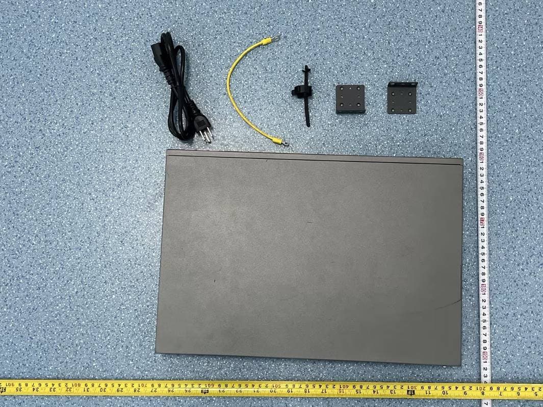
Click to zoom
Application Details
- Equipment Class
- JAD - Part 15 Class A Digital Device
- Date of Grant
- May 09, 2023
- Application Purpose
- Original Equipment
- Date of Application
- May 09, 2023
- Equipment Note
- Enterprise Layer 2+ Stackable Managed Network Switch
- Company
- Grandstream Networks, Inc.
- Country
- United States
Documents & Files
Document Text
Text extracted from the exhibit documents filed with the FCC. Open a document above to read the original.
Users Manual
Grandstream Networks, Inc. 126 Brookline Ave, 3rd Floor Boston, MA 02215. USA Tel : +1 (617) 566 - 9300 www.grandstream.com For Certification, Warranty and RMA information, please visit www.grandstream.com GWN7806-GWN7806P Enterprise Layer 2+ Stackable Managed Network Switch Quick Installation Guide ~ 2 ~~ 1 ~ EN OVERVIEW The GWN7806(P) is layer 2+ stackable managed switch that allows small-to-medium enterprises to build scalable, secure, high performance and smart business networks that are fully manageable. It supports advanced VLAN for flexible and sophisticated traffic segmentation, advanced QoS for priori- tization of network traffic, IGMP/MLD Snooping for network performance optimization, and compre- hensive security capabilities against potential attacks. The GWN7806P provides smart dynamic PoE output to power IP phones, IP cameras, Wi-Fi access points and other PoE endpoints. GWN7806(P) is easy to deploy and manage, including managed by the local Web user interface of the GWN7806(P) switch and CLI, the command-line interface. The switch is also supported by GWN.Cloud and GWN Manager, Grandstream’s cloud and on-premise network management platform. The GWN7806(P) is the best value enterprise-grade managed network switch for small-to-medium businesses. PRECAUTIONS •Do not attempt to open, disassemble, or modify the device. •Do not expose this device to temperature outside range of 0 °C to 45 °C for operation and -10 °C to 60 °C for storage. •Do not expose this device to environments outside of the following humidity range: 10-90% RH (non- condensing) for operation and 10-90% RH (non-condensing) for storage. •Do not power cycle your GWN7806(P) during system boot up or firmware upgrade. You may corrupt firmware images and cause the unit to malfunction. PACKAGE CONTENTS PORTS & LED INDICATORS No.Port & LEDDescription 1Port 1-48 48x Ethernet RJ45(10/100/1000Mbps), used for connecting terminals Note: GWN7806P Ethernet ports support PoE/PoE+ 21-48Ethernet ports’ LED indicators 3Port SFP+ 49-54 6x 10Gbps SFP+ ports 4 SFP+ 49-54SFP+ ports’ LED indicators 5Console 1x Console port, used to connect a PC directly to the switch and manage it. 6RST Factory Reset pinhole Press for 5 seconds to reset factory default settings 7SYSSystem LED indicator 8Power cord anti-trip hole 9 100-240VAC 50-60HzPower socket 10Grounding terminal 11 Fan3x Fans 1 2 3 4 5 6 7 1x GWN7806(P) Switch 1x 25cm Ground Cable 1x 1.2m (10A) AC Cable 4x Rubber Footpads 8x Screws (KM 3*6) 2x Rack Mounting Kits 1x Quick Installation Guide 1x Power Cord Anti-Trip 11 10 9 8 LED Indicator Front Panel Back Panel Side Panel LED Indicator StatusDescription System Indicator OffPower off Solid greenBooting Flashing greenUpgrade Solid blueNormal use Flashing blue Provisioning Solid red Upgrade failed Flashing redFactory reset Port Indicator OffFor all ports, port off & For SFP+ ports, port failure Solid greenPort connected and there is no activity Flashing greenPort connected and data is transferring Solid yellowEthernet port connected and PoE powered Flashing yellowEthernet port connected, data is transferring and PoE powered Alternately flashing yellow and greenEthernet port failure ~ 4 ~~ 3 ~ Powering on the Switch Connect the power cable and the switch first, then connect the power cable to the power supply system of the equipment room. Grounding the Switch 1. Remove the ground screw from the back of switch, and connect one end of the ground cable to the wiring terminal of switch. 2. Put the ground screw back into the screw hole, and tighten it with a screwdriver. 3. Connect the other end of the ground cable to other device that has been grounded or directly to the terminal of the ground bar in the equipment room. Connecting Power Cord Anti-Trip 1. Force the head of the fixing strap tightly into the hole next to the power socket until it’s buckled on the shell without falling off. In order to protect the power supply from accidental disconnection, it’s recommended to use a power cord anti-trip for installation. Ground Terminal Ground Cable Ground Bar 2. After plugging the power cord into the power outlet, slide the protector over the remaining strap until it slides over the end of the power cord. 3. Wrap the strap of the protective cord around the power cord and lock it tightly. Fasten the straps until the power cord is securely fastened. POWERING & CONNECTING PORT CONNECTING Connect to RJ45 Port 1. Connect one end of the network cable to the switch, and the other end to the peer device. 2. After powered on, check the status of the port indicator. If on, it means that the link is connected normally; if off, it means the link is disconnected, please check the cable and the peer device whether is enabled. Crystal head Ethernet RJ45 RJ45 port RJ45 port Connect to SFP+ Port The installation process of the fiber module is as follows: 1. Grasp the fiber module from the side and insert it smoothly along the switch SFP+ port slot until the module is in close contact with the switch. 2. When connecting, pay attention to confirm the Rx and Tx ports of SFP+ fiber module. Insert one end of the fiber into the Rx and Tx ports correspondingly, and connect the other end to another device. 3. After powered on, check the status of the port indicator. If on, it means that the link is connected normally; if off, it means the link is disconnected, please check the cable and the peer device whether is enabled. Notes: • Please select the optical fiber cable according to the module type. The multi-mode module corresponds to the multi-mode optical fiber, and the single-mode module corresponds to the single-mode optical fiber. • Please select the same wavelength optical fiber cable for connection. • Please select an appropriate optical module according to the actual networking situation to meet different transmission distance requirements. • The laser of the first-class laser products is harmful to eyes. Do not look directly at the optical fiber connector. Fibe…
Text truncated - open the document above for the full version.
Attestation Statements
Grandstream Networks, Inc. Address: 126 Brookline Ave, 3rd Floor Boston, MA 02215, USA Tel: 1-617-5669300; Fax: 1-617-2491987 Email: [email protected] Product Power Similarity Declaration Date: 2023/04/23 FEDERAL COMMUNICATIONS COMMISSIONS Authorization and Evaluation Division 7435 Oakland Mills Road Columbia, MD 21046 Dear Sir/Madam, We, Grandstream Networks, Inc., hereby declare that we have a product named as Enterprise Layer 2+ Stackable Managed Network Switch, FCC ID: YZZGWN7806P (model:GWN7806P) was tested by China Certification ICT Co., Ltd (Dongguan), meanwhile, for our marketing purpose, the GWN7806P will be configured with two different AC power modules, the other is the same. We confirm that all information above is true, and we’ll be responsible for all the consequences. Please contact me if you have any question. Sincerely Yours, Signature: Ning Wei Manager
Attestation Statements
Grandstream Networks, Inc. 126 Brookline Ave, 3rd Floor Boston, MA 02215, USA Tel: 1-617-5669300 Fax: 1-617-2491987 Email: [email protected] CFR 47 §2.911(d)(5)(i) Attestation Letter Attestation Letter Date: 2023/04/23 FEDERAL COMMUNICATIONS COMMISSIONS Authorization and Evaluation Division 7435 Oakland Mills Road Columbia, MD 21046 Ref: Attestation Statements CFR 47 §2.911(d)(5)(i) Filing FCC ID: YZZGWN7806P Grandstream Networks, Inc. certifies that the equipment for which authorization is sought is not “covered” equipment prohibited from receiving an equipment authorization pursuant to section 2.903 of the FCC rules. Sincerely, Signature Contact Person: Ning Wei Title:Manager Company Name & Address: Grandstream Networks, Inc. &126 Brookline Ave, 3rd Floor Boston, MA 02215, USA
Attestation Statements
Grandstream Networks, Inc. 126 Brookline Ave, 3rd Floor Boston, MA 02215, USA Tel: 1-617-5669300 Fax: 1-617-2491987 Email: [email protected] CFR 47 §2.911 (d)(5)(ii) Attestation Letter Attestation Letter Date: 2023/04/23 FEDERAL COMMUNICATIONS COMMISSIONS Authorization and Evaluation Division 7435 Oakland Mills Road Columbia, MD 21046 Ref: Attestation Statements CFR 47 §2.911(d)(5)(ii) Filing FCC ID: YZZGWN7806P Grandstream Networks, Inc. certifies that as of the date of the filing of the application, the applicant is not identified on the Covered List as an entity producing “covered” equipment. Sincerely, Signature Contact Person: Ning Wei Title:Manager Company Name & Address: Grandstream Networks, Inc.&126 Brookline Ave, 3rd Floor Boston, MA 02215, USA
Attestation Statements
U.S. AGENT LETTER OF ATTESTATION Date: 2023-04-23 FEDERAL COMMUNICATIONS COMMISSION Authorization and Evaluation Division 7435 Oakland Mills Road Columbia, MD 21046 Ref: Attestation Statements CFR 47 §2.911(d)(7) Filing FCC ID: YZZGWN7806P Grandstream Networks, Inc. certifies that, as of the date of the filing of the application, Grandstream Networks, Inc. is our designated U.S. agent for service of process for the above referenced FCC ID. Grandstream Networks, Inc. accepts to maintain an agent for no less than one year after the grantee has terminated all marketing and importation or the conclusion of any Commission-related proceeding involving the equipment. Grandstream Networks, Inc. accepts, as of the date of the filing of the application, the obligation of the designated U.S. agent for service of process for the above referenced FCC ID. Designated U.S. Agent and Applicant Information: Name: Grandstream Networks, Inc. Address: 126 Brookline Ave, 3rd Floor Boston, MA 02215, USA FRN: 0020352431 Tel.: 1-617-5669300 Email: [email protected] Signed by (printed name): Ning Wei Signature:
Cover Letter(s)
Grandstream Networks, Inc. 126 Brookline Ave, 3rd Floor Boston, MA 02215, USA Tel: 1-617-5669300 Fax: 1-617-2491987 Email: [email protected] QA-FR-170-B 7/29/2014 FCC Authorization Date: 2023-04-23 FEDERAL COMMUNICATIONS COMMISSIONS Authorization and Evaluation Division 7435 Oakland Mills Road Columbia, MD 21046 Subject: Agent Authorization To whom it may concern: We Grandstream Networks, Inc., the undersigned, hereby authorizes China Certification ICT Co., Ltd (Dongguan) to act on its behalf in all matters relating to application for Equipment authorization, including the signing of all documents relating to these matters. All acts carried out by China Certification ICT Co., Ltd (Dongguan) on our behalf shall have the same effect as our own action. We, the undersigned, hereby certify that we are not subject to a denial of federal benefits, that includes FCC benefits, pursuant to Section 5301 of the Anti-Drug Abuse Act of 1988, 21 U.S.C. 862. This authorization is valid until further written notice from the applicant. Sincerely Yours, Signature: Ning Wei Manager
Cover Letter(s)
Grandstream Networks, Inc. 126 Brookline Ave, 3rd Floor Boston, MA 02215, USA Tel: 1-617-5669300 Fax: 1-617-2491987 Email: [email protected] FCC Confidential Authorization Date: 2023-04-23 FEDERAL COMMUNICATIONS COMMISSIONS Authorization and Evaluation Division 7435 Oakland Mills Road Columbia, MD 21046 Subject: Confidentiality Request regarding application for certification of FCC ID: YZZGWN7806P In accordance with Sections 0.457 and 0.459 of the Commission’s Rules, Grandstream Networks, Inc. hereby requests long-term confidential treatment of information accompanying this application as outlined below: Block Diagram Schematics Operation Description The above materials contain proprietary and confidential information not customarily released to the public. The public disclosure of these materials provides unjustified benefits to its competitors in the market. Sincerely Yours, Signature: Ning Wei Manager
External Photos
EXHIBIT B - EUT EXTERNAL PHOTOGRAPHS EUT Port
ID Label/Location Info
3 3-R1 36.00mm 100.00mm Model: GWN7806PINPUT: 100-240V~ 50-60Hz 8A This device complies with part 15 of the FCC rules. Operation is subject to the following two conditions: (1) this device may not cause harmful interference, and (2) this device must accept any interference received, including interference that may cause undesired operation. FCC ID:YZZGWN7806PCAN ICES-003(A) / NMB-003(A)Made in China S/N XXXXXXXXXXXXXXXX MAC XXXXXXXXXXXX Password: XXXXXXXX P/N XXX-XXXXX-XXXXX www.grandstream.comGrandstream Networks, lnc. 126 Brookline Avenue, 3rd Floor Boston, MA 02215, USA
Internal Photos
EXHIBIT C - EUT INTERNAL PHOTOGRAPHS Power Supply 1 G1489-0460W Power Supply 1 G1489-0460W Power Supply 2 PA-2431-54H1 Power Supply 2 PA-2431-54H1 Power Supply 2 PA-2431-54H1
Test Report
TEST REPORT Applicant: Grandstream Networks, Inc. Address: 126 Brookline Ave., 3rd Floor Boston, MA 02215, USA FCC ID: YZZGWN7806P Product Name: Enterprise Layer 2+ Stackable Managed Network Switch Model Number: GWN7806P Standard(s): 47 CFR Part 15 Subpart B ANSI C63.4-2014 The above equipment has been tested and found compliant with the requirement of the relative standards by China Certification ICT Co., Ltd (Dongguan) Report Number: CR230314894-00A Date Of Issue: 2023/4/20 Reviewed By: Sun Zhong Title: Manager Test Laboratory: China Certification ICT Co., Ltd (Dongguan) No. 113, Pingkang Road, Dalang Town, Dongguan, Guangdong, China Tel: +86-769-82016888 China Certification ICT Co., Ltd (Dongguan) Report No.: CR230314894-00A Page 2 of 27 Test Facility The Test site used by China Certification ICT Co., Ltd (Dongguan) to collect test data is located on the No. 113, Pingkang Road, Dalang Town, Dongguan, Guangdong, China. The lab has been recognized as the FCC accredited lab under the KDB 974614 D01 and is listed in the FCC Public Access Link (PAL) database, FCC Registration No. : 442868, the FCC Designation No. : CN1314. The lab has been recognized by Innovation, Science and Economic Development Canada to test to Canadian radio equipment requirements, the CAB identifier: CN0123. Declarations China Certification ICT Co., Ltd (Dongguan) is not responsible for the authenticity of any test data provided by the applicant. Data included from the applicant that may affect test results are marked with a triangle symbol “▲”. Customer model name, addresses, names, trademarks etc. are not considered data. Unless otherwise stated the results shown in this test report refer only to the sample(s) tested. This report cannot be reproduced except in full, without prior written approval of the Company. This report is valid only with a valid digital signature. The digital signature may be available only under the Adobe software above version 7.0. This report may contain data that are not covered by the accreditation scope and shall be marked with an asterisk “★”. China Certification ICT Co., Ltd (Dongguan) Report No.: CR230314894-00A Page 3 of 27 CONTENTS TEST FACILITY ............................................................................................................................................................. 2 DECLARATIONS ............................................................................................................................................................ 2 DOCUMENT REVISION HISTORY ......................................................................................................................... 4 1. GENERAL INFORMATION ................................................................................................................................... 5 1.1 PRODUCT DESCRIPTION FOR EQUIPMENT UNDER TEST (EUT) ............................................................................... 5 1.2 DESCRIPTION OF TEST CONFIGURATION ................................................................................................................ 6 1.2.2 Support Equipment List and Details .............................................................................................................. 6 1.2.3 Support Cable List and Details ...................................................................................................................... 6 1.2.4 Block Diagram of Test Setup ......................................................................................................................... 7 1.3 MEASUREMENT UNCERTAINTY .............................................................................................................................. 8 2. SUMMARY OF TEST RESULTS ........................................................................................................................... 9 3. REQUIREMENTS AND TEST PROCEDURES ................................................................................................. 10 3.1 AC LINE CONDUCTED EMISSIONS ........................................................................................................................ 10 3.1.1 EUT Setup.................................................................................................................................................... 10 3.1.2 EMI Test Receiver Setup ............................................................................................................................. 10 3.1.3 Test Procedure ............................................................................................................................................. 11 3.1.4 Corrected Amplitude & Margin Calculation ................................................................................................ 11 3.2 RADIATION SPURIOUS EMISSIONS ........................................................................................................................ 12 3.2.1 EUT Setup.................................................................................................................................................... 12 3.2.2 EMI Test Receiver Setup ............................................................................................................................. 13 3.2.3 Test Procedure ............................................................................................................................................. 13 3.2.4 Corrected Amplitude & Margin Calculation ................................................................................................ 13 4. TEST DATA AND RESULTS ................................................................................................................................ 14 4.1 AC LINE CONDUCTED EMISSIONS ........................................................................................................................ 14 4.2 RADIATION SPURIOUS EMISSIONS ............................…
Text truncated - open the document above for the full version.
Test Setup Photos
EXHIBIT D - TEST SETUP PHOTOGRAPHS Conducted emissions front View-M1&M2 Conducted emissions side View-M1&M2 Radiated Emissions Below 1G front View-M1&M2 Radiated Emissions Below 1G Rear View-M1&M2 Radiated Emissions Above 1G front View-M1&M2 Radiated Emissions Above 1G Rear View-M1&M2
Contact Information
Applicant
Ning Wei
Test Firm
CHINA CERTIFICATION ICT CO., LTD (DONGGUAN)Tanie Ou
[email protected]0086 0769 86858888
Technical Specifications
| # | Rule Parts | Frequency Range | Power Output |
|---|---|---|---|
| 1 | 15B | - | - |
Other Applications from Grandstream Networks, Inc.
YZZGWN7712P
Sep 04, 2026Layer 2 Lite Managed Network PoE Switch
Equipment Class
JAD - Part 15 Class A Digital DeviceYZZGWN7801PC
Aug 27, 2026Enterprise Layer 2+ Compact Managed Switch
Equipment Class
JAD - Part 15 Class A Digital DeviceYZZGWN7823P
Aug 26, 2026Layer 3 Multi-Gigabit Network Switch
Equipment Class
JAD - Part 15 Class A Digital DeviceYZZGWN7703P
Aug 26, 202624 Unmanaged Gigabit Port and 2 SFP Port Switch with 24 PoE+
Equipment Class
JAD - Part 15 Class A Digital DeviceYZZGWN7673
Jul 29, 2026Dual-Band Wi-Fi 7 Access Point
Equipment Class
DTS - Digital Transmission System