YZZGXV3651IP Camera
Grandstream Networks, Inc.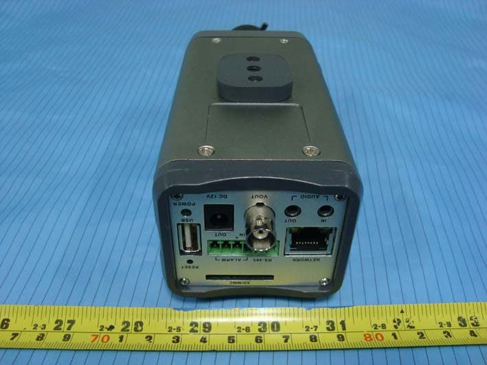
Click to zoom
Application Details
- Equipment Class
- JBP - Part 15 Class B Computing Device Peripheral
- Date of Grant
- Jan 26, 2011
- Application Purpose
- Original Equipment
- Date of Application
- Jan 26, 2011
- Equipment Note
- IP Camera
- Company
- Grandstream Networks, Inc.
- Country
- United States
Documents & Files
Document Text
Text extracted from the exhibit documents filed with the FCC. Open a document above to read the original.
Users Manual
Grandstream Networks, Inc. GXV3651 Series User Manual GXV3651 IP Camera Firmware 1.0.4.6 Page 2 of 35 Grandstream Networks, Inc. 09/2010 Safety Instructions These instructions are intended to assist users with the operation of the GXV3651 and also to instruct on how to avoid dangerous situations or damage to the device. Warnings: Serious injury or death may be caused if any of the warnings below are neglected. Cautions: Injury or damage to the equipment may occur if any of the following caution messages are neglected. Warnings Follow these safeguards to prevent serious injury or death. Cautions Follow these precautions to prevent potential injury or material damage. Warnings: Input voltage should meet both the SELV (Safety Extra Low Voltage) and the Limited Power Source with DC 12V according to the IEC60950-1 standard. Please refer to the technical specifications for more details. Do not use a third-party power adapter or power cord When the device is installed on the wall or ceiling, make sure that it is firmly attached. Notice: Make sure that the power supply voltage is correct before using the camera. Do not drop the device or expose it to physical shock. Do not expose the device to temperatures outside the range of -10 o C to +60 o C when the device is in operation. Do not expose the device to damp/wet conditions or high electromagnetism radiation. To avoid heat accumulation, make sure that your operating environment has proper ventilation. Do not attempt to open, disassemble, or modify the device A few parts (e.g. electrolytic capacitor) of the equipment shall be replaced regularly according to their average life time. The average life time varies from the differences between operating environments and usage history. Regular maintenance checks are recommended for all users. Please contact your dealer for more details. GXV3651 IP Camera Firmware 1.0.4.6 Page 3 of 35 Grandstream Networks, Inc. 09/2010 Contents Welcome .........................................................................................................................................................4 Package Contents ............................................................................................................................................5 Product Overview ...........................................................................................................................................6 GXV3651 Overview ...............................................................................................................................6 GXV3651 Back Panel.............................................................................................................................6 GXV3651 Sample Connection Diagram.................................................................................................7 GXV3651 Key Features..........................................................................................................................7 GXV3651 Lens Specification .................................................................................................................8 Minimum Recommended System Requirement ...................................................................................10 Connect your GXV3651 .......................................................................................................................10 Configuring the GXV3651 via Web Browser ...............................................................................................11 Access GXV3651 Web Configuration Menu........................................................................................11 Connect the Camera to DHCP server....................................................................................................11 Connect to the Camera using Static IP. .................................................................................................12 GXV3651 Home Web Page ..................................................................................................................13 GXV3651 System Page ........................................................................................................................14 GXV3651 Video & Audio Page............................................................................................................15 GXV3651 Networking Page – Assign an IP to GXV3651 ...................................................................17 GXV3651 DDNS Page .........................................................................................................................18 GXV3651 SIP Page ..............................................................................................................................18 GXV3651 Status Page ..........................................................................................................................20 GXV3651 User Management Page.......................................................................................................21 GXV3651 Maintenance Page ...............................................................................................................22 GXV3651 SMTP Page..........................................................................................................................23 GXV3651 FTP Page .............................................................................................................................23 GXV3651 PTZ Page .............................................................................................................................24 GXV3651 Alarm Event.........................................................................................................................25 GXV3651 Motion Detection Page........................................................................................................28 Configure Motion Detection & Alarm Actions ........................................................…
Text truncated - open the document above for the full version.
Cover Letter(s)
Company: Grandstream Networks, Inc. Address: 5F, Bldg #1, No.2 Kefa Rd., Science & Technology Park,ShenZhen,China FCC Confidential Authorization Date: 2011-01-10 FEDERAL COMMUNICATIONS COMMISSIONS Authorization and Evaluation Division 7435 Oakland Mills Road Columbia, MD 21046 Confidentiality Request regarding application for certification of FCC ID: YZZGXV3651 Pursuant to Sections 0.457 and 0.459 of the Commission’s Rules, we hereby request confidential treatment of information accompanying this application as outlined below: • Detailed Circuit Schematics of EUT--- (Long term) Block Diagram--- (Long term) Circuit Description--- (Long term) The above materials contain trade secrets and proprietary information not customarily released to the public. The public disclosure of these materials may be harmful to the applicant and provide unjustified benefits to its competitors. The applicant understands that pursuant to Section 0.457 of the Rules, disclosure of this application and all accompanying documentation will not be made before the date of the Grant for this application. Sincerely Yours, Signature: Typed or Printed Name: Ning Wei Title: Senior Director of Production Company Name: Grandstream Networks, Inc.
External Photos
EXHIBIT B - EUT EXTERNAL PHOTOGRAPHS Model: GXV3651_FHD & GXV3651_HD EUT – Front View EUT – Rear View EUT – Side View
ID Label/Location Info
EXHIBIT A - FCC ID LABELING AND LOCATION FCC ID Label FCC ID Label Location The label shown shall be permanently affixed at a conspicuous location on the device and be readily visible to the user at the time purchase (Labeling requirements per 2.925) GXV3651_FHD GXV3651_HD GXV3651_FHD & GXV3651_HD
Internal Photos
EXHIBIT C - EUT INTERNAL PHOTOGRAPHS EUT – Cover off View EUT – Main Board 1 Front View EUT –Main Board 1 Rear View EUT – Main Board 2 Front View EUT –Main Board 2 Rear View EUT – Main Board 3 Front View EUT –Main Board 3Rear View EUT – Camera Board Front View EUT –Camera Board Rear View
Test Report
Note: This test report is prepared for the customer shown above and for the device described herein. It may not be duplicated or used in part without prior written consent from Bay Area Compliance Laboratories Corp. This report must not be used by the customer to claim product certification, approval, or endorsement by NVLAP*, NIST, or any agency of the Federal Government. * This report contains data that are not covered by the NVLAP accreditation and are marked with an asterisk “★” (Rev.2) FCC PART 15B MEASUREMENT AND TEST REPORT For Grandstream Networks, Inc. 5F, Bldg #1, No.2 Kefa Rd., Science & Technology Park, Shenzhen, Guangdong, China FCC ID: YZZGXV3651 Report Type: Original Report Product Type: IP Camera Test Engineer: Cabin Hu Report Number: RSZ10112604 Report Date: 2011-01-21 Reviewed By: Lisa Zhu EMC Engineer Prepared By: Bay Area Compliance Laboratories Corp. (Shenzhen) 6/F, the 3rd Phase of WanLi Industrial Building, ShiHua Road, FuTian Free Trade Zone Shenzhen, Guangdong, China Tel: +86-755-33320018 Fax: +86-755-33320008 Grandstream Networks, Inc. FCC ID: YZZGXV3651 Report No.: RSZ10112604 Page 2 of 47 FCC Part 15B Test Report TABLE OF CONTENTS GENERAL INFORMATION.......................................................................................................................................3 PRODUCT DESCRIPTION FOR EQUIPMENT UNDER TEST (EUT) ....................................................................................3 OBJECTIVE...................................................................................................................................................................3 RELATED SUBMITTAL(S)/GRANT(S).............................................................................................................................3 TEST METHODOLOGY..................................................................................................................................................3 TEST FACILITY.............................................................................................................................................................4 SYSTEM TEST CONFIGURATION ..........................................................................................................................5 JUSTIFICATION.............................................................................................................................................................5 EQUIPMENT MODIFICATIONS.......................................................................................................................................5 LOCAL SUPPORT EQUIPMENT LIST AND DETAILS........................................................................................................5 EXTERNAL I/O CABLE..................................................................................................................................................5 CONFIGURATION OF TEST SETUP.................................................................................................................................6 BLOCK DIAGRAM OF TEST SETUP................................................................................................................................7 SUMMARY OF TEST RESULTS ...............................................................................................................................8 FCC §15.107 – AC LINE CONDUCTED EMISSIONS .............................................................................................9 MEASUREMENT UNCERTAINTY....................................................................................................................................9 EUT SETUP..................................................................................................................................................................9 EMI TEST RECEIVER SETUP.......................................................................................................................................10 TEST EQUIPMENT LIST AND DETAILS.........................................................................................................................10 TEST PROCEDURE......................................................................................................................................................10 TEST RESULTS SUMMARY..........................................................................................................................................10 TEST DATA................................................................................................................................................................11 FCC §15.109 – RADIATED SPURIOUS EMISSIONS............................................................................................20 MEASUREMENT UNCERTAINTY..................................................................................................................................20 EUT SETUP................................................................................................................................................................20 EMI TEST RECEIVER SETUP.......................................................................................................................................21 TEST EQUIPMENT LIST AND DETAILS.........................................................................................................................21 TEST PROCEDURE......................................................................................................................................................21 CORRECTED AMPLITUDE & MARGIN CALCULATION.................................................................................................21 TEST RESULTS SUMMARY..........................................................................................................................................22 TEST DATA..............................................................…
Text truncated - open the document above for the full version.
Test Setup Photos
EXHIBIT D - TEST SETUP PHOTOGRAPHS AC/DC adapter Power Supply Conducted Disturbance at Mains Terminals - Front View Conducted Disturbance at Mains Terminals - Side View Radiated Disturbance - Front View (Below 1GHz) Radiated Disturbance - Rear View (Below 1GHz) Radiated Disturbance - Front View (Above 1GHz) Radiated Disturbance - Rear View (Above 1GHz) POE power supply: Conducted Disturbance at Mains Terminals - Front View Conducted Disturbance at Mains Terminals - Side View Radiated Disturbance - Front View (Below 1GHz) Radiated Disturbance - Rear View (Below 1GHz) Radiated Disturbance - Front View (Above 1GHz) Radiated Disturbance - Rear View (Above 1GHz) Radiated Disturbance - Front View (Above 1GHz) Radiated Disturbance - Rear View (Above 1GHz)
Contact Information
Applicant
Ning Wei
Test Firm
Bay Area Compliance Laboratory Corp. (Shenzhen)John Chan
Technical Specifications
| # | Rule Parts | Frequency Range | Power Output |
|---|---|---|---|
| 1 | 15B | - | - |
Other Applications from Grandstream Networks, Inc.
YZZGWN7712P
Sep 04, 2026Layer 2 Lite Managed Network PoE Switch
Equipment Class
JAD - Part 15 Class A Digital DeviceYZZGWN7801PC
Aug 27, 2026Enterprise Layer 2+ Compact Managed Switch
Equipment Class
JAD - Part 15 Class A Digital DeviceYZZGWN7823P
Aug 26, 2026Layer 3 Multi-Gigabit Network Switch
Equipment Class
JAD - Part 15 Class A Digital DeviceYZZGWN7703P
Aug 26, 202624 Unmanaged Gigabit Port and 2 SFP Port Switch with 24 PoE+
Equipment Class
JAD - Part 15 Class A Digital DeviceYZZGWN7673
Jul 29, 2026Dual-Band Wi-Fi 7 Access Point
Equipment Class
DTS - Digital Transmission System