Z2CCTRAX2.4 GHz Transceiver Module
Contact Controls, LLC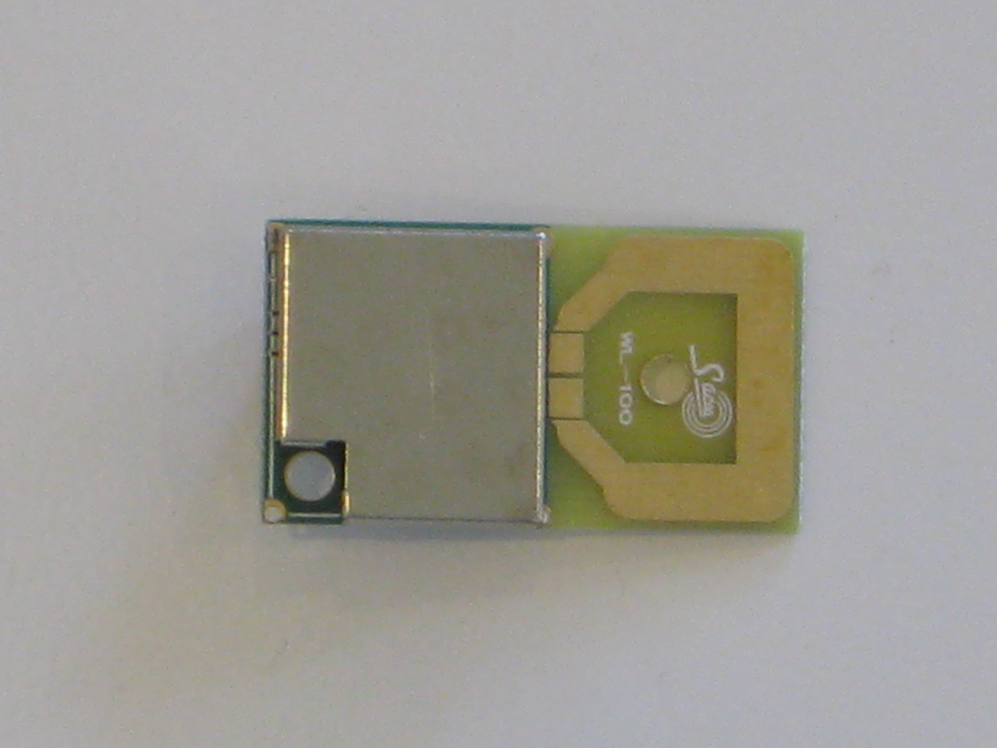
Click to zoom
Application Details
- Equipment Class
- DXT - Part 15 Low Power Transceiver, Rx Verified
- Date of Grant
- Jan 25, 2012
- Application Purpose
- Original Equipment
- Date of Application
- Jan 25, 2012
- Equipment Note
- 2.4 GHz Transceiver Module
- Frequency Range
- 2402.00000000 - 2482.00000000
- Company
- Contact Controls, LLC
- Country
- United States
Documents & Files
Document Text
Text extracted from the exhibit documents filed with the FCC. Open a document above to read the original.
Users Manual
Instructions for use of the Contact Controls, FCC ID: Z2CCTRAX module: 1. Must be installed by Contact Controls in a Contact Controls host system 2. May not be installed in any host system that contains another transmitter operating within 20cm (co-location) 3. The host system label must include the following statement: “Contains FCC ID: Z2CCTRAX” 4. The user’s manual for the host system must contain the following statements: a. The FCC 2part statement per 15.19(a)(3) – “This device complies with Part 15 of the FCC Rules. Operation is subject to the following two conditions: (1) this device may not cause harmful interference, and (2) this device must accept any interference received, including interference that may cause undesired operation.” b. A warning to the user that any changes or modifications not expressly approved by Contact Controls could void the user’s authority to operate the equipment. Per FCC 15.21.
Cover Letter(s)
Page 1 of 1 Elliott TCB 684 W. Maude Ave Sunnyvale, CA, 94085 To whom it may concern: The enclosed documents constitute a formal submittal and application for Equipment Authorization for a 2.4GHz modular transceiver pursuant to the following rules: Subpart C of Part 15 of FCC Rules (CFR 47), per 15.249 The application is for full modular approval. The module is intended for use with only those hosts developed by the applicant. Elliott Laboratories, as duly authorized agent prepared this submittal. A copy of the letter of our appointment as agent is included with the application. If there are any questions or if further information is needed, please contact Elliott Laboratories for assistance. Sincerely, Mark Hill Staff Engineer
Cover Letter(s)
Z2CCTRAX
Cover Letter(s)
982 Main Street Suite 4, PMB 118 Fishkill, NY 12524 Modular Approval Requirements Full Modular Approval is being requested for this device. The following paragraphs detail the requirements for modules and explain how the module meets those requirements. Where requirements are not met a justification for a limited modular approval is presented. FCC §15.212 Requirements for Single Modular Transmitters (includes RSS GEN Section 3.2.2) (a) Single modular transmitters consist of a completely self-contained radiofrequency transmitter device that is typically incorporated into another product, host or device. Split modular transmitters consist of two components: a radio front end with antenna (or radio devices) and a transmitter control element (or specific hardware on which the software that controls the radio operation resides). All single or split modular transmitters are approved with an antenna. All of the following requirements apply, except as provided in paragraph (b) of this section. (1) Single modular transmitters must meet the following requirements to obtain a modular transmitter approval. (i) The radio elements of the modular transmitter must have their own shielding. The physical crystal and tuning capacitors may be located external to the shielded radio elements. The module contains its own metal shield located on the module’s PCB that covers all RF circuitry. (ii) The modular transmitter must have buffered modulation/data inputs (if such inputs are provided) to ensure that the module will comply with part 15 requirements under conditions of excessive data rates or over-modulation. Data to the modulation circuit is buffered on the module via U1. (iii) The modular transmitter must have its own power supply regulation. The module contains its own power supply regulation and the rf reference oscillator is contained within the module. Power supply regulation is provided via U1. (iv) The modular transmitter must comply with the antenna and transmission system requirements of §§15.203, 15.204(b) and 15.204(c). The antenna must either be permanently attached or employ a “unique” antenna coupler (at all connections between the module and the antenna, including the cable). The “professional installation” provision of §15.203 is not applicable to modules but can apply to limited modular approvals under paragraph (b) of this section. The module connects to its antenna via a PCB trace on the same PCB. (v) The modular transmitter must be tested in a stand-alone configuration, i.e., the module must not be inside another device during testing for compliance with part 15 requirements. Unless the transmitter module will be battery powered, it must comply with the AC line conducted requirements found in §15.207. AC or DC power lines and data input/output lines connected to the module must not contain ferrites, unless they will be marketed with the module (see §15.27(a)). The length of these lines shall be the length typical of actual use or, if that length is unknown, at least 10 centimeters to insure that there is no coupling between the case of the module and supporting equipment. Any accessories, peripherals, or support equipment connected to the module during testing shall be unmodified and commercially available (see §15.31(i)). Test data contained in this application is for the device tested in a stand-alone configuration. Radiated spurious emissions data and AC conducted emissions data demonstrating compliance with the requirements of Part 15 of the FCC rules for intentional radiators and RSS GEN/RSS 210 has been provided. (vi) The modular transmitter must be equipped with either a permanently affixed label or must be capable of electronically displaying its FCC identification number. (A) If using a permanently affixed label, the modular transmitter must be labeled with its own FCC identification number, and, if the FCC identification number is not visible when the module is installed inside another device, then the outside of the device into which the module is installed must also display a label referring to the enclosed module. This exterior label can use wording such as the following: “Contains Transmitter Module FCC ID: XYZMODEL1” or “Contains FCC ID: XYZMODEL1.” Any similar wording that expresses the same meaning may be used. The Grantee may either provide such a label, an example of which must be included in the application for equipment authorization, or, must provide adequate instructions along with the module which explain this requirement. In the latter case, a copy of these instructions must be included in the application for equipment authorization. (B) If the modular transmitter uses an electronic display of the FCC identification number, the information must be readily accessible and visible on the modular transmitter or on the device in which it is installed. If the module is installed inside another device, then the outside of the device into which the module is installed must display a label referring to the enclosed module. This exterior label can use wording such as the following: “Contains FCC certified transmitter module(s).” Any similar wording that expresses the same meaning may be used. The user manual must include instructions on how to access the electronic display. A copy of these instructions must be included in the application for equipment authorization. The module is appropriately labeled (refer to the label and label location drawings contained within this application). Instructions to the end user regarding the labeling requirements for host devices are included in this application. (vii) The modular transmitter must comply with any specific rules or operating requirements that ordinarily apply to a complete transmitter and the manufacturer must provide adequate instructions along with the module to explain any such requirements. A copy of these instructions must be included in the application for equipment authorization. The module complies with the specif…
Text truncated - open the document above for the full version.
ID Label/Location Info
SHEET 1 OF 1 SCALE N/A SIZE 101904 WIRELESS MODULE LABEL LOCATION DRAWING AB CD AB CD 1 32 4 65 1 32 4 65 DRAWING NO. REV AA DRAWN:CHECKED:ENGINEER:RELEASED: UNLESS OTHERWISE SPECIFIED DIMENSIONS ARE IN INCHES .X .XX .XXX +/- .0 +/-.00 +/-.001 REV DESCRIPTION APPROVED DATE ECN REVISIONS RELEASED TO PRODUCTION C C TM C ontact C ontrols, LLC C. WICHMAN – 11/06/11C. WICHMAN – 11/06/11C. WICHMAN – 11/06/11C. WICHMAN – 11/06/11 FCC ID:Z2CCTRAX NOTES:SHIELD OF WIRELESS MODULE.PLACE ITEM# 1 APPROXIMATELY IN THE AREA SHOWN ON TOP OF THE SHIELD OF THE WIRELESS MODULE. WIRELESS MODULE TOP VIEW ( NOT TO SCALE) ITEM PART NUMBER DESCRIPTION PARTS LIST 101903 1 1 1 2 1 2 WIRELESS MODULE LABEL DRAWING QTY 11
Test Report
File: R84652 Page 1 EMC Test Report Application for Grant of Equipment Authorization FCC Part 15 Subpart C Model: 2.4GHz Transceiver Module for Ctrax CT Series FCC ID: Z2CCTRAX APPLICANT: Contact Controls 982 Main Street Suite 4, PMB 118 Fishkill, NY 12524 TEST SITE(S): Elliott Laboratories 41039 Boyce Road. Fremont, CA. 94538-2435 IC SITE REGISTRATION #: 2845B-3; 2845B-5 REPORT DATE: December 21, 2011 FINAL TEST DATES: August 11, 12 and 31, September 1 and October 21, 2011 TOTAL NUMBER OF PAGES: 38 PROGRAM MGR / QUALITY ASSURANCE DELEGATE / TECHNICAL REVIEWER: FINAL REPORT PREPARER: ______________________________ ______________________________ Mark E Hill David Guidotti Staff Engineer Senior Technical Writer Elliott Laboratories is accredited by the A2LA, certificate number 2016.01, to perform the test(s) listed in this report, except where noted otherwise. This report and the information contained herein represent the results of testing test articles identified and selected by the client performed to specifications and/or procedures selected by the client. National Technical Systems (NTS) makes no representations, expressed or implied, that such testing is adequate (or inadequate) to demonstrate efficiency, performance, reliability, or any other characteristic of the articles being tested, or similar products. This report should not be relied upon as an endorsement or certification by NTS of the equipment tested, nor does it represent any statement whatsoever as to its merchantability or fitness of the test article, or similar products, for a particular purpose. This report shall not be reproduced except in full Elliott Laboratories -- EMC Department Test Report Report Date: December 21, 2011 File: R84652 Page 2 REVISION HISTORY Rev# Date Comments Modified By - 12-21-2011 First release Elliott Laboratories -- EMC Department Test Report Report Date: December 21, 2011 File: R84652 Page 3 TABLE OF CONTENTS REVISION HISTORY ................................................................................................................................................2 TABLE OF CONTENTS ............................................................................................................................................3 SCOPE..........................................................................................................................................................................4 OBJECTIVE ................................................................................................................................................................4 STATEMENT OF COMPLIANCE...........................................................................................................................5 DEVIATIONS FROM THE STANDARDS ..............................................................................................................5 TEST RESULTS SUMMARY ...................................................................................................................................6 DEVICES OPERATING IN THE 902 – 928 / 2400 – 2483.5 / 5725 – 5850 MHZ BANDS PER 15.249 ...............6 GENERAL REQUIREMENTS APPLICABLE TO ALL BANDS..........................................................................6 MEASUREMENT UNCERTAINTIES....................................................................................................................7 EQUIPMENT UNDER TEST (EUT) DETAILS ......................................................................................................8 GENERAL................................................................................................................................................................8 OTHER EUT DETAILS...........................................................................................................................................8 ANTENNA SYSTEM ..............................................................................................................................................8 ENCLOSURE...........................................................................................................................................................8 MODIFICATIONS...................................................................................................................................................8 SUPPORT EQUIPMENT.........................................................................................................................................8 EUT INTERFACE PORTS ......................................................................................................................................8 EUT OPERATION ...................................................................................................................................................8 TEST SITE...................................................................................................................................................................9 GENERAL INFORMATION ...................................................................................................................................9 CONDUCTED EMISSIONS CONSIDERATIONS ................................................................................................9 RADIATED EMISSIONS CONSIDERATIONS ....................................................................................................9 MEASUREMENT INSTRUMENTATION ............................................................................................................10 RECEIVER SYSTEM ............................................................................................................................................10 INSTRUMENT CONTROL COMPUTER ............................................................................................................10 LINE IMPEDANCE STABILIZATION NETWORK (LISN)...........................................................................…
Text truncated - open the document above for the full version.
Contact Information
Applicant
Christopher Wichman(CEO)
Technical Contact
Elliott Laboratories LLCMark Hill
[email protected]510 578 3500
41039 Boyce Road · Fremont, California · United States
Test Firm
Elliott Laboratories LLCDavid Bare
Technical Specifications
| # | Rule Parts | Frequency Range | Power Output |
|---|---|---|---|
| 1 | 15C | 2.40 GHz - 2.48 GHz | - |