Z2L812675Radio controller for car heating
Teltronic AG
Click to zoom
Application Details
- Equipment Class
- DSR - Part 15 Remote Control/Security Device Transceiver
- Date of Grant
- Feb 02, 2012
- Application Purpose
- Original Equipment
- Date of Application
- Feb 02, 2012
- Equipment Note
- Radio controller for car heating
- Frequency Range
- 433.16600000 - 433.16600000
- Company
- Teltronic AG
- Country
- Switzerland
Documents & Files
Document Text
Text extracted from the exhibit documents filed with the FCC. Open a document above to read the original.
Users Manual
Modul Preview .......................................3 Modul Preview U2 ....................................4 Auxiliary heating ................................ 4 Contents 1 Index .......................................................2 A Auxiliary heating Before switching on ........................... 5 Fault ................................................11 Heater booster function ..................... 9 Remote control ..............................7, 9 Safety notes ....................................... 4 Switch ................................................ 5 Switching the remote control on/ off ...................................................... 7 Switch-on time ................................... 5 Synchronising the remote control ...... 8 B Battery Changing (auxiliary heating remote control) .................................. 9 H Heater booster function ....................... 9 P Practical advice Auxiliary heating ..............................11 R Remote control Auxiliary heating ................................ 7 Changing the batteries (auxiliary heating) .............................................. 9 2 Index Modul Preview U2 .................................4 3 Modul Preview Modul Preview U2 Auxiliary heating Important safety notes G WARNING Exhaust fumes are produced while the auxiliary heating system is in operation. If you breathe in these exhaust fumes, you could be poisoned. Therefore, always switch off the auxiliary heating in enclosed spaces without an extraction system, e.g. a garage. G WARNING Parts of the vehicle can become very hot during operation of the auxiliary heating. Make sure that the exhaust system does not under any circumstances come into contact with highly flammable material such as dry grass or fuels. Otherwise, the highly flammable material could ignite and set the vehicle alight. Auxiliary heating operation is prohibited at gas stations or when your vehicle is being refueled. Therefore, the auxiliary heating must be switched off at gas stations. The auxiliary heating system operates inde- pendently of the engine and complements the vehicle heating or air conditioning. You can use the auxiliary heating at an out- side temperature of up to 39 ‡ (4 †) in order to: R pre-heat the vehicle interior R additionally warm the coolant, thereby con- serving the engine and saving fuel R support the vehicle's heating system while the engine is running and outside tempe- ratures are low (heater booster function) i At an outside temperature above 39 ‡ (4 †), the auxiliary heating system and the heater booster function switch off automa- tically. ! Switch on the auxiliary heating system at regular intervals (at least once a month) for approximately 10 minutes. Make sure that the flow of hot air is not blocked. Otherwise, the auxiliary heating will overheat and switch off. i If the interior motion sensor is armed and the auxiliary heating is switched on, it is possible that the interior temperature monitoring may cause a false alarm. In this case, either deactivate the interior motion sensor or switch off the auxiliary heating. You can switch the auxiliary heating on/off using: R the on-board computer and the auxiliary heating switch (Y Seite 5) or R the auxiliary heating remote control (Y Seite 7). i USA only: This device complies with part 15 of the FCC Rules. Operation is subject to the fol- lowing two conditions: (1) this device may not cause harmful inter- ference, and (2) this device must accept any interfe- rence received, including interference that may cause undesired operation. Changes or modifications made to this equipment not expressly approved by Telt- ronic AG may void the FCC authorization to operate this equipment. This equipment has been tested and found to comply with the limits for a Class B digital device, pursuant to Part 15 of the FCC Rules. These limits are designed to provide reasonable protection against harmful interference in a residential installation. This equipment generates, uses and can radiate radio frequency energy and, if not installed and used in accordance with the instructions, may cause harmful interfe- rence to radio communications. However, there is no guarantee that interference will not occur in a particular installation. 4 Modul Preview U2 Modul Preview If this equipment does cause harmful inter- ference to radio or television reception, which can be determined by turning the equipment off and on, the user is encoura- ged to try to correct the interference by one or more of the following measures: R Reorient or relocate the receiving antenna. R Increase the separation between the equipment and receiver. R Connect the equipment into an outlet on a circuit different from that to which the receiver is connected. R Consult the dealer or an experienced radio/TV technician for help. i Canada only: Licence exempt This device complies with Industry Canada licence-exempt RSS standard(s). Opera- tion is subject to the following two conditi- ons: (1) this device may not cause interference, and (2) this device must accept any interfe- rence, including interference that may cause undesired operation of the device. Before switching on X The fuel tank must be at least one-quarter full. X Set the desired temperature using the tem- perature control of the heating or the air- conditioning system . X Set the air distribution as required . X Open the center and side air vents and set them to the middle position . i The auxiliary heating automatically swit- ches to heater booster mode after the engine is started. Operating using the switch : To switch the auxiliary heating on/off ; To switch the heater booster function on/ off (Y Seite 9) X To switch on the auxiliary heating: press the y switch for longer than 2 seconds. R The auxiliary heating heats or ventilates the interior to the temperature that you have set. R The blower switches to the first level. R The red indicator lamp in the switch comes on. X To switch off the auxiliary h…
Text truncated - open the document above for the full version.
External Photos
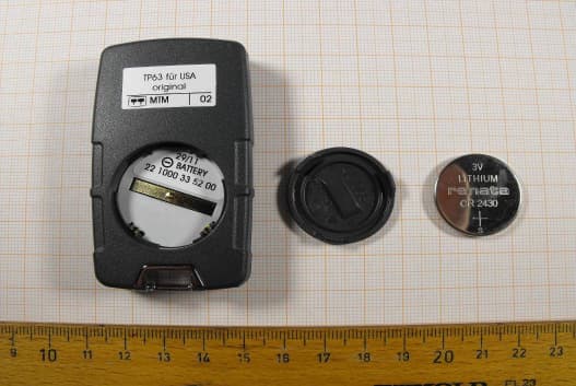
Test report no.: 1-2894-01-02/10 2011-09-22 Page 29 of 42 An ne x B E x te rna l ph ot ogra phs o f the E UT Photo documentation: Photo 1: Photo 2: Test report no.: 1-2894-01-02/10 2011-09-22 Page 30 of 42 Photo 3: Photo 4: Test report no.: 1-2894-01-02/10 2011-09-22 Page 31 of 42 Photo 5: Photo 6: Test report no.: 1-2894-01-02/10 2011-09-22 Page 32 of 42 Photo 7: (Antenna) Photo 8: Test report no.: 1-2894-01-02/10 2011-09-22 Page 33 of 42 Photo 9: Photo 10: Test report no.: 1-2894-01-02/10 2011-09-22 Page 34 of 42 Photo 11: Photo 12: Test report no.: 1-2894-01-02/10 2011-09-22 Page 35 of 42 Photo 13: Photo 14:
Internal Photos
Test report no.: 1-2894-01-02/10 2011-09-22 Page 36 of 42 An ne x C Inte r na l p ho to gra phs o f the E UT Photo documentation: Photo 1: Photo 2: Test report no.: 1-2894-01-02/10 2011-09-22 Page 37 of 42 Photo 3: Photo 4: Test report no.: 1-2894-01-02/10 2011-09-22 Page 38 of 42 Photo 5: Photo 6: Test report no.: 1-2894-01-02/10 2011-09-22 Page 39 of 42 Photo 7: Photo 8: Test report no.: 1-2894-01-02/10 2011-09-22 Page 40 of 42 Photo 9: Photo 10: Test report no.: 1-2894-01-02/10 2011-09-22 Page 41 of 42 Photo 11: Photo 12:
Test Report
2012-02-03 Page 1 of 42 TEST REPORT Test report no.: 1-2894-01-02/10-A Testing laboratory Applicant CETECOM ICT Services GmbH Untertuerkheimer Strasse 6 – 10 66117 Saarbruecken / Germany Phone: + 49 681 5 98 - 0 Fax: + 49 681 5 98 - 9075 Internet: http://www.cetecom.com e-mail: [email protected] Accredited test laboratory: The test laboratory (area of testing) is accredited according to DIN EN ISO/IEC 17025 DAkkS registration number: D-PL-12076-01-01 Area of Testing: Radio/Satellite Communications Teltronic AG Gewerbestrasse 9 4562 Biberist / SWITZERLAND Phone: +41 3 26 71 61 11 Fax: +41 3 26 71 61 12 Contact: Klaus von Arx e-mail: [email protected] Phone: +41 3 26 71 61 05 Manufacturer Teltronic AG Gewerbestrasse 9 4562 Biberist / SWITZERLAND Test standard/s 47 CFR Part 15 Title 47 of the Code of Federal Regulations; Chapter I Part 15 - Radio frequency devices RSS - 210 Issue 8 Spectrum Management and Telecommunications - Radio Standards Specification Low-power Licence-exempt Radiocommunication Devices (All Frequency Bands): Category I Equipment For further applied test standards please refer to section 3 of this test report. Test item Kind of test item: Radio controller for car heating Model name: EasyStart R Daimler USA ST FCC ID: Z2L812675 IC: 9912A-10003397000 Frequency: 433.166 MHz Power supply: 12 V DC Temperature range: -10 °C to +55 °C This test report is electronically signed and valid without handwriting signature. For verification of the electronic signatures, the public keys can be requested at the testing laboratory. Test performed: Test report authorised: Stefan Bös Marco Bertolino Senior Testing Manager Testing Manager Test report no.: 1-2894-01-02/10-A 2012-02-03 Page 2 of 42 1 Table of contents 1 Table of contents ............................................................................................................................................ 2 2 General information ....................................................................................................................................... 3 2.1 Notes ..................................................................................................................................................... 3 2.2 Application details ............................................................................................................................... 3 3 Test standard/s ............................................................................................................................................... 3 4 Test environment ............................................................................................................................................ 3 5 Test item .......................................................................................................................................................... 4 6 Test laboratories sub-contracted ................................................................................................................. 4 7 Summary of measurement results ............................................................................................................... 5 8 RF measurements .......................................................................................................................................... 6 8.1 Description of test setup .................................................................................................................... 6 8.1.1 Radiated measurements............................................................................................................. 6 8.1.2 Conducted measurements.......................................................................................................... 7 8.2 Additional comments .......................................................................................................................... 7 8.3 RSP100 test report cover sheet / performance test data ................................................................ 8 9 Measurement results ...................................................................................................................................... 9 9.1 Timing of the transmitter .................................................................................................................... 9 9.2 Switch off time ................................................................................................................................... 10 9.3 Emission bandwidth .......................................................................................................................... 11 9.4 Field strength of the fundamental ................................................................................................... 12 9.5 Field strength of the harmonics and spurious ............................................................................... 13 9.6 Receiver spurious emission (radiated) ........................................................................................... 18 10 Test equipment and ancillaries used for tests ................................................................................... 23 Annex A Photographs of the test setup ...................................................................................................... 25 Annex B External photographs of the EUT ................................................................................................. 29 Annex C Internal photographs of the EUT .................................................................................................. 36 Annex D Document history .......................................................................................................................... 42 Annex E Further information ........................................................................................................................ 42 Test report no.: 1-2894-01-02/10-A 2012-02-03 Page 3 of 42 2 General info…
Text truncated - open the document above for the full version.
Test Setup Photos
Test report no.: 1-2894-01-02/10 2011-09-22 Page 25 of 42 An ne x A P ho tog ra phs o f t h e te s t s e tu p Photo documentation: Photo 1: Chamber F Photo 2: Chamber F Test report no.: 1-2894-01-02/10 2011-09-22 Page 26 of 42 Photo 3: Chamber C Photo 4: Chamber C Test report no.: 1-2894-01-02/10 2011-09-22 Page 27 of 42 Photo 5: Chamber C Photo 6: Chamber C Test report no.: 1-2894-01-02/10 2011-09-22 Page 28 of 42 Photo 7: Chamber C Photo 8: Chamber C
Contact Information
Applicant
Viktor Stooss
Test Firm
cetecom advanced GmbHGerald Schmidt
Technical Specifications
| # | Rule Parts | Frequency Range | Power Output |
|---|---|---|---|
| 1 | 15.231 | 433.166 MHz - 433.166 MHz | - |
Other Applications from Teltronic AG
Z2L812674
Feb 02, 2012Remote control for car heating
Equipment Class
DSR - Part 15 Remote Control/Security Device Transceiver