Z33-CA1Central Alert
Serene Innovations Inc.
Click to zoom
Application Details
- Equipment Class
- DXT - Part 15 Low Power Transceiver, Rx Verified
- Date of Grant
- Dec 26, 2011
- Application Purpose
- Original Equipment
- Date of Application
- Dec 26, 2011
- Equipment Note
- Central Alert
- Frequency Range
- 2422.00000000 - 2422.00000000
- Company
- Serene Innovations Inc.
- Country
- United States
Documents & Files
Document Text
Text extracted from the exhibit documents filed with the FCC. Open a document above to read the original.
Users Manual
User’s Guide Model CA-360 Operating Guide Thank you for purchasing this product. Please read before use. (Keep this manual for future reference) Central Alert 1. Table of Contents CentralAlert TM Features 2. Important safety instructions 3. General 4. Package contents 4. Installation and test 5. Set clock 5. Set alarm time 6. Select 12/24 hour mode 6. Telephone test 7. Doorbell and test 7. CA 360 Accessories list 8. FCC Information/warranty, etc. 9. 2. CentralAlert TM Features: • 2.4 GHz technology - 360° full coverage of your entire home. • An audio alarm, bright flasher, visual icons, and a bed-shaker to alert you to daily sounds: alarm clock, doorbell, phone/cell/video calls/fax, smoke/gas alarms, a baby’s cry, a weather warning, a motion sensor, and more. • A large, easy-to-see clock with dual alarms. • Dual bed shaker output jacks (one bed shaker included). • No installation needed - just “plug and use.” • Two phone jacks for separate telephone/fax/video phone. • Weather resistant, easily installed wireless doorbell included. • A battery powered back-up (batteries not included). Note: * A June 2007 study by the Fire Protection Foundation found that a low frequency square wave signal (such as 520 Hz) is most effective in alerting a hard-of-hearing person. 3. Important Safety Instructions : When using a CentralAlert TM Model CA-360, in order to reduce the risk of fire, electric shock or injury to persons, basic safety precautions should always be followed, including the following: 1. Read all instructions before using appliance. 2. This product uses rechargeable batteries. Do not use non- rechargeable batteries as charging of this type can cause battery leakage. 3. Always disconnect phone cord from wall jack before changing/installing batteries. 4. To reduce injury risk, close supervision is necessary when appliance is used near children. 5. Do not contact moving parts or exposed metal surfaces. 6. Only use attachments recommended/sold by the manufacturer. 7. Do not use outdoors. Do not use near water. 8. To disconnect, turn all controls to “Off” position, then remove plug from outlet. 9. Do not unplug the unit by pulling the cord - grasp plug, not cord. 10. Unplug unit from outlet when not in use/before servicing or cleaning. 11. Do not operate an appliance with a damaged cord or plug; do not operate any appliance after it malfunctions, is dropped or damaged in any manner. Return appliance to nearest authorized service facility for examination, repair, or electrical/mechanical adjustment. 12. To Reduce Risk of Electric Shock, this appliance has a polarized plug (one blade wider than the other). This plug fits a polarized outlet only one way. If the plug doesn’t fit, reverse the plug. If it still doesn’t fit, contact a qualified electrician to install a proper outlet. Do not change plug in any way. 13. Avoid using telephone products during electrical storms. There’s an electric shock risk from lightning. 14. Don’t use telephone to report a gas leak while in the vicinity of the leak. 15. Specifications of this product are subject to change without notice. 4. General : CentralAlert™ Model CA-360 is an advanced wireless visual alert system for the hard-of-hearing (HOH). It also serves as a dual-alarm clock with a 1.25” high digital display (green in color). It uses an exclusive Smart-Code technology and operates in the 2.4 GHZ band. This technology offers a fast response and long range operation. It can support thousands of systems without the need for channel-setting switches. The system alerts users to ten (10) different household functions/events using four (4) alerting outputs: Speaker, flasher, bed-shaker, and digital display. The digital display shows the names of the activated functions. (Some functions require an optional accessory to be purchased.) The standard system comes with: a Master-Unit, a wireless doorbell, a bed- shaker, an AC cord, a phone cord, this manual and a Quick Guide. The wireless doorbell has already been registered to the Master-Unit. The entire system is ready for use. Additional wireless sensors, bed-shakers, and remote receivers may be purchased to cover a larger home or office. New sensors must be registered to the Master-Unit before they can be recognized (See Adding an Extra Doorbell ). Four AA-size rechargeable NiMH batteries (not included) provide 48-hours of power outage backup. This backup duration is the longest in its class. Package Contents : 5. Master-Unit Installation and Testing : 1. Install four AA size rechargeable NiMH batteries (user provided) in battery compartment at bottom of unit. Warning: Do not use regular batteries as charging of this type can cause battery leakage and damage to the CentralAlert TM unit. (The unit works without batteries; they may be inserted for back up, in case of power outage) 2. Plug AC adapter into nearest electrical outlet and connect adapter plug to CentralAlert TM Master-Unit as shown. 3. Connect bed shaker to SHAKER-1 output jack. 4. Connect phone cord to PHONE-1 outlet at the back of Master-Unit, then plug the other end into wall phone jack. 5. Set the SPEAKER ( - on left side of unit) to desired volume setting (Hi- Lo-Off). 6. Press SOS button on top of unit (next to Motion button) to test. Verify that alert outputs (speaker, flasher, shaker, and display) last for 30 seconds, then stop. 7. Verify that flasher can be toggled ON and OFF using SNOOZE / RESET button. Set the Clock: 1. Slide SET switch (on right side of unit) to TIME position and push HR & MIN buttons to set time. The unit’s face will show the AM time with a lighted dot beside “Sun AM” icon. No dot means PM. Holding in HR/MIN switch to forward the hours will not work. Push button repeatedly. 2. After completing time setting, slide SET switch to RUN position for normal clock operation. 2 3 4 6 7 5 6. Set the Alarm Time : 1. Slide SET switch (on right side of unit) to Alarm -1 (AL 1) position and set alarm time using HR and MIN buttons. Holding …
Text truncated - open the document above for the full version.
External Photos
EXHIBIT B - EUT EXTERNAL PHOTOGRAPHS EUT – Front View EUT – Rear View EUT – Top View EUT – Side View EUT – Adapter View EUT – Adapter Label View
ID Label/Location Info
EXHIBIT A - FCC ID LABELING AND LOCATION FCC ID Label FCC ID Label Location The label shown shall be permanently affixed at a conspicuous location on the device and be readily visible to the user at the time purchase (Labeling requirements per 2.925)
Internal Photos
EXHIBIT C - EUT INTERNAL PHOTOGRAPHS EUT – Battery off View EUT – Cover off View EUT – Main Board Top View ` ` EUT – Main Board Bottom View PCB Antenna EUT – RF Module Shielding off Top View EUT –RF Module Bottom View PCB Antenna
Test Report
Note: This test report is prepared for the customer shown above and for the equipment described herein. It may not be duplicated or used in part without prior written consent from Bay Area Compliance Laboratories Corp. This report must not be used by the customer to claim product certification, approval, or endorsement by NVLAP*, or any agency of the Federal Government. * This report contains data that are not covered by the NVLAP accreditation and are marked with an asterisk “★” (Rev.2) FCC PART 15.249 TEST REPORT For Serene Innovations Inc. 14731 Carmenita Road, Norwalk, CA 90650, USA FCC ID: Z33-CA1 Report Type: Original Report Product Type: Central Alert Test Engineer: Allan An Report Number: RSZ110922002-00 Report Date: 2011-12-12 Reviewed By: Alvin Huang EMC Engineer Test Laboratory: Bay Area Compliance Laboratories Corp. (Shenzhen) 6/F, the 3rd Phase of WanLi Industrial Building, ShiHua Road, FuTian Free Trade Zone Shenzhen, Guangdong, China Tel: +86-755-33320018 Fax: +86-755-33320008 www.baclcorp.com.cn Bay Area Compliance Laboratories Corp. (Shenzhen) Report No.: RSZ110922002-00 FCC Part 15.249 Page 2 of 15 TABLE OF CONTENTS GENERAL INFORMATION.......................................................................................................................................3 PRODUCT DESCRIPTION FOR EQUIPMENT UNDER TEST (EUT) .....................................................................................3 OBJECTIVE...................................................................................................................................................................3 RELATED SUBMITTAL(S)/GRANT(S).............................................................................................................................3 TEST METHODOLOGY..................................................................................................................................................3 TEST FACILITY.............................................................................................................................................................3 SYSTEM TEST CONFIGURATION ..........................................................................................................................5 DESCRIPTION OF TEST CONFIGURATION......................................................................................................................5 EQUIPMENT MODIFICATIONS.......................................................................................................................................5 CONFIGURATION OF TEST SETUP.................................................................................................................................5 BLOCK DIAGRAM OF TEST SETUP................................................................................................................................5 SUMMARY OF TEST RESULTS ...............................................................................................................................6 FCC §15.203 - ANTENNA REQUIREMENT.............................................................................................................7 APPLICABLE STANDARD..............................................................................................................................................7 ANTENNA CONNECTOR CONSTRUCTION......................................................................................................................7 FCC §15.207 (A) – AC LINE CONDUCTED EMISSIONS ......................................................................................8 APPLICABLE STANDARD..............................................................................................................................................8 MEASUREMENT UNCERTAINTY....................................................................................................................................8 EUT SETUP..................................................................................................................................................................8 EMI TEST RECEIVER SETUP.........................................................................................................................................9 TEST EQUIPMENT LIST AND DETAILS...........................................................................................................................9 TEST PROCEDURE........................................................................................................................................................9 TEST RESULTS SUMMARY............................................................................................................................................9 TEST DATA..................................................................................................................................................................9 FCC §15.205, §15.209 & §15.249 - RADIATED EMISSIONS ................................................................................12 APPLICABLE STANDARD............................................................................................................................................12 MEASUREMENT UNCERTAINTY..................................................................................................................................12 TEST EQUIPMENT SETUP............................................................................................................................................12 EUT SETUP................................................................................................................................................................13 TEST PROCEDURE......................................................................................................................................................13 CORRECTED AMPLITUDE & MARGIN CALCULATION.........................................................…
Text truncated - open the document above for the full version.
Test Setup Photos
EXHIBIT D - TEST SETUP PHOTOGRAPHS Conducted Emissions - Front View Conducted Emissions - Rear View Radiated Emissions
Contact Information
Applicant
Peter Lee(VP- Technologies)
Test Firm
Bay Area Compliance Laboratory Corp. (Shenzhen)John Chan
Technical Specifications
| # | Rule Parts | Frequency Range | Power Output |
|---|---|---|---|
| 1 | 15C | 2.42 GHz - 2.42 GHz | - |
Other Applications from Serene Innovations Inc.

Z33-RCX
Jul 16, 2015RCx-Remote Transmitter
Equipment Class
DSC - Part 15 Security/Remote Control Transmitter
Z33-PG1
Jul 14, 20152-Way Paging
Equipment Class
DSC - Part 15 Security/Remote Control Transmitter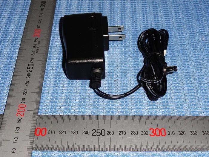
Z33-TVSB
Oct 20, 2013Wireless TV Speaker
Equipment Class
DTS - Digital Transmission System
Z33-CA2
Dec 19, 2011Central Alert Remote
Equipment Class
DXT - Part 15 Low Power Transceiver, Rx Verified
Z33-CA3
Dec 19, 2011Central Alert Remote
Equipment Class
DXT - Part 15 Low Power Transceiver, Rx Verified