Z63-001AONIBluetooth Headset
SHENZHEN AONI ELECTRONIC CO., LTD.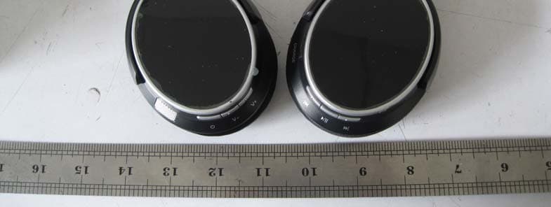
Click to zoom
Application Details
- Equipment Class
- DSS - Part 15 Spread Spectrum Transmitter
- Date of Grant
- Nov 10, 2011
- Application Purpose
- Original Equipment
- Date of Application
- Nov 03, 2011
- Equipment Note
- Bluetooth Headset
- Frequency Range
- 2402.00000000 - 2480.00000000
- Country
- China
Documents & Files
Document Text
Text extracted from the exhibit documents filed with the FCC. Open a document above to read the original.
Users Manual
Bluetooth Headset Manual Thank you for purchasing the ANS 304 stereo Headset with Bluetooth Wireless technology, we encourage you to read this quick installation guide thoroughly to get the most of this innovative wireless headset. 1.Package content: Headset; USB cable charger; User manual. 2.Button function: 1. Volume up (+) 2. Volume down (-) 3. Power on/off button 4. Microphone 5. Previous track 6. Play/pause button 7. Next track 8. USB interface for charging Status indicator: ·Alternating red and green LEDs indicate headset has entered into the pairing mode and ready to be detectable for the first time. ·Green LED flashing slowly indicates the device is powered on and/or connected · Solid red LED indicates the battery is charging. When the battery has reached full capacity, the solid red LED will go off. 3. Charge your headset ·Use the supplied USB cable to charge the battery directly from your PC. ·Make sure that your ANS 304 headset is fully charged before using it for the first time. ·The headset battery has to be initially charged for at least for 4 hours. Thereafter, the battery will take from 2 to 3 hours to recharge. 4. Advanced operation Note: Before installing this product, please make sure your computer or laptop has the built-in bluetooth feature available. If your computer is not bluetooth-enabled, your must purchase a bluetooth dongle, preferably version 2.1 or above. a. Pairing the headphones with your computer 1. Make sure the headset is off. 2. Activate the bluetooth program in your computer to beging setup. 3. The “Search new device” screen will be displayed. 4. Place both devices not more than one meter away from each other. 5. Press the power button on the headset to turn it on. The green and red LEDs will start blinking in sequential order. This indicates that the headset has entered pairing mode. 6. As soon as the system detects the new device in your dialog box, double click the icon representing the headset. 7. The software may activate the passkey window and ask you to enter the PIN code =”0000”(4 zero). Otherwise, the wireless connection will be established automatically with the remote device. 8. If the pairing is successful, the green LED will start blinking slowly, If after 60 seconds the pairing process fails, please repeat steps 1 through 7 describled above. 9. The headset will go automatically into standby mode after a short period of inactivity. b. Pairing the headphones with your phone 1. Make sure the headset is off. 2. Set your bluetooth phone to “discover” the wireless headset. 3. Place both devices not more than one meter away from each other. 4. Press the power button on the headset to turn it on. The green and red LEDs will start blinking fast in sequential order. This indicates that the headset has entered pairing mode. 5. Follow the phone instruction, your phone, upon detecting the wireless headset, will ask if you want to pair with it. 6. Accept by pressing “Yes” or “OK” on the phone, if prompted, enter the passkey =”0000”(4 zero). Your phone will confirm when pairing is complete. 7. If the pairing is successful, the green LED will start blinking slowly, If after 60 seconds the pairing process fails, please repeat steps 1 through 6 describled above. 9. The headset will go automatically into standby mode after a short period of inactivity. 5. Answering and ending a call using your mobile phone ·When there is an incoming call, the headset will ring. · Briefly press the power button to answer an incoming call. You may also press the answer button on your cellular phone to receive the call in your headset. Music playback pauses temporarily. ·To end a call simply tap the power button once again. Likewise, you may also end the call directly using your cell phone. As soon as your hang up, music playback resumes automatically. 6. Specifications: Mic. Spec.: Microphone Unit: ¢6*5mm Directivity: omnidirectional S.P.L: -58±2dB Impedance: ≤2.2KΩ Frequency response:20Hz-20,000Hz Operating Voltage: 4.5V Speaker Spec.: Speaker diameter:¢40mm Impedance:32Ω S.P.L: 118±3dB S.P.L at 1KHZ Rated power: 20mW Aggregate capability: 50mW Frequency response: 20Hz-20,000Hz Power: Battery type: Built-in 400mAh Lithium-polymer rechargeable battery Charging connector type: USB Plug Run time: Up to 6 hours of talking or music playback time Standby time: Up to 90 hours Charging time: 2 hours Operating Temperature: -10 o C - 45 o C Storage Temperature: -25 o C - 60 o C 7. Attention: 1. If you cannot power on the headset, please check your power, charge it. 2. Please remember to power off the headset when you don’t use. 3. If you don’t use the headset for a long time, pls. charge it before using. 4. Do NOT disassemble, repair or modify the headset by yourself. 5. Do NOT store the device in a place with high humidity or dust 6. Please don't storage it where the temperature is beyond 45 degree. 8.Note: The device has been evaluated to meet general RF exposure requirement. The device can be used in portable exposure condition without restriction. 9.Warning: Changes or modifications to this unit not expressly approved by the party responsible for compliance could void the user’s authority to operate the equipment.
External Photos
EXTERNAL PHOTOS OF EUT External View of EUT-1 External View of EUT-2
Internal Photos
INTERNAL PHOTOS OF EUT Internal View of EUT-1 Internal View of EUT-2
RF Exposure Info
FCC ID : Z63-001AONI Portable device According to §15.247(e)(i) and §1.1307(b)(1), systems operating under the provisions of this section shall be operated in a manner that ensures that the public is not exposed to radio frequency energy level in excess of the Commission’s guidelines. According to KDB 447498 (2)(a)(i) Frequency Range Low Frequency (MHz) High Frequency(MHz) Center frequency (MHz) 60/f SAR Limitation (mw) 2402 2480 2402 25 Maximum measured transmitter power Conducted Power (mw) Max Antenna Gain (dBi) EIRP (mw) 1.7 0 1.7 Threshold at which no SAR required is 25 mw. Maximum Tx power is 1.7mw EIRP. Conclusion: No SAR is required. SIMULTANEOUS TRANSMISSION EVALUATION N/A
Test Report
Report No. : EESZD10200001 Page 1 of 39 ELECTROMAGNETIC EMISSIONS COMPLIANCE REPORT INTENTIONAL RADIATOR CERTIFICATION Product Name : Bluetooth Headset Model Number : BT304 / BT311 Trade Name : N/A FCC ID : Z63-001AONI Report Number : EESZD10200001 Date : November 11, 2011 Prepared for: SKYPINE ELECTRONICS (SHENZHEN) CO., LTD. A1 Building, No.6 Xinxing Industrial Park, Xinhe Village, Fuyong Town, Baoan District, Shenzhen, China. Prepared by: CENTRE TESTING INTERNATIONAL Building C, Hongwei Industrial Zone, Baoan 70 District, Shenzhen, Guangdong, China TEL: +86-755-3368 3668 FAX: +86-755-3368 3385 Check No.: 115111337 This report shall not be reproduced, except in full, without the written approval of CENTRE TESTING INTERNATIONAL Building C, Hongwei Industrial Zone, Baoan 70 District, Shenzhen Standards Results 47 CFR FCC Part 15 Subpart C 15.247: 2010 PASS Report No. : EESZD10200001 Page 2 of 39 TABLE OF CONTENTS Description Page 1. CERTIFICATION INFORMATION ............................................................................................................... 4 2. TEST SUMMARY ........................................................................................................................................ 5 3. MEASUREMENT UNCERTAINTY .............................................................................................................. 5 4. PRODUCT INFORMATION ......................................................................................................................... 5 5. SYSTEM TEST CONFIGURATION.............................................................................................................. 6 6. TEST EQUIPMENT LIST............................................................................................................................. 7 7. SUPPORT EQUIPMENT LIST .................................................................................................................... 7 8. 20DB BANDWIDTH MEASUREMENT ....................................................................................................... 8 8.1. LIMITS ................................................................................................................................................. 8 8.2. BLOCK DIAGRAM OF TEST SETUP.................................................................................................. 8 8.3. TEST PROCEDURE ........................................................................................................................... 8 8.4. TEST RESULT .................................................................................................................................... 8 9. CARRIER FREQUENCY SEPARATION ...................................................................................................11 9.1. LIMITS ............................................................................................................................................... 11 9.2. BLOCK DIAGRAM OF TEST SETUP................................................................................................ 11 9.3. TEST PROCEDURE ......................................................................................................................... 11 9.4. TEST RESULT .................................................................................................................................. 11 10. NUMBER OF HOPPING FREQUENCY................................................................................................ 13 10.1. LIMITS ............................................................................................................................................... 13 10.2. BLOCK DIAGRAM OF TEST SETUP................................................................................................ 13 10.3. TEST PROCEDURE ......................................................................................................................... 13 10.4. TEST RESULT .................................................................................................................................. 13 11. TIME OF OCCUPANCY (DWELL TIME)................................................................................................... 14 11.1. LIMITS ............................................................................................................................................... 14 11.2. BLOCK DIAGRAM OF TEST SETUP................................................................................................ 14 11.3. TEST PROCEDURE ......................................................................................................................... 14 11.4. TEST RESULT .................................................................................................................................. 14 Report No. : EESZD03140005 Page 3 of 39 12. MAXIMUM PEAK CONDUCTED OUTPUT POWER MEASUREMENT .............................................. 18 12.1. LIMITS ............................................................................................................................................... 18 12.2. BLOCK DIAGRAM OF TEST SETUP................................................................................................ 18 12.3. TEST PROCEDURE ......................................................................................................................... 18 12.4. TEST RESULT .................................................................................................................................. 18 13. BAND EDGE EMISSION MEASUREMENT ......................................................................................... 20 13.1. LIMITS ............................................................................................................................................... 20 13.2. BLOCK DIAGRAM OF TEST SETUP...................................................................................…
Text truncated - open the document above for the full version.
Test Setup Photos
TEST SETUP PHOTOS TEST SETUP OF RADIATED EMISSION (30MHz-1GHz) TEST SETUP OF RADIATED EMISSION (above 1GHz)
Contact Information
Applicant
tendy Dong
Test Firm
CENTRE TESTING INTERNATIONAL CORPORATIONChristy Chen
Technical Specifications
| # | Rule Parts | Frequency Range | Power Output |
|---|---|---|---|
| 1 | 15C | 2.40 GHz - 2.48 GHz | 1.70 mW |
Other Applications from SHENZHEN AONI ELECTRONIC CO., LTD.
Z63-O6K98PRO
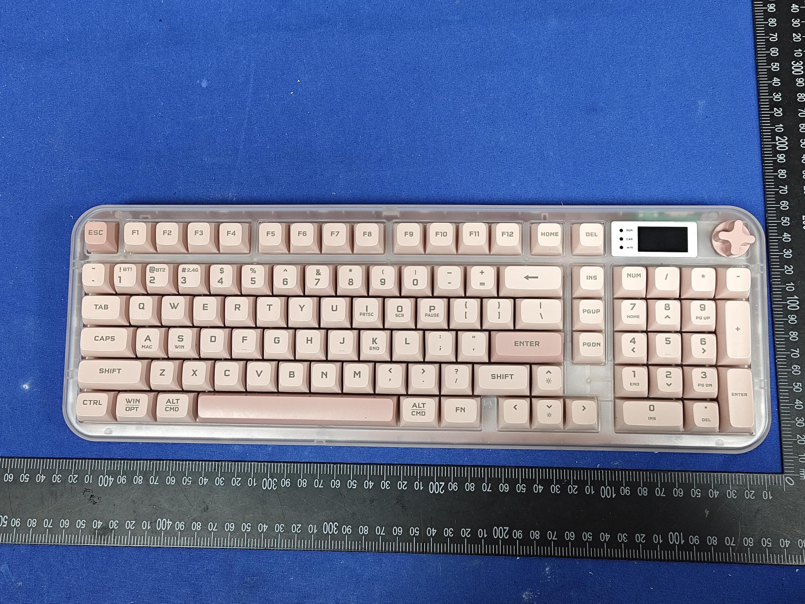
Mar 23, 2026Wireless Triple-Mode Keyboard
Equipment Class
DTS - Digital Transmission System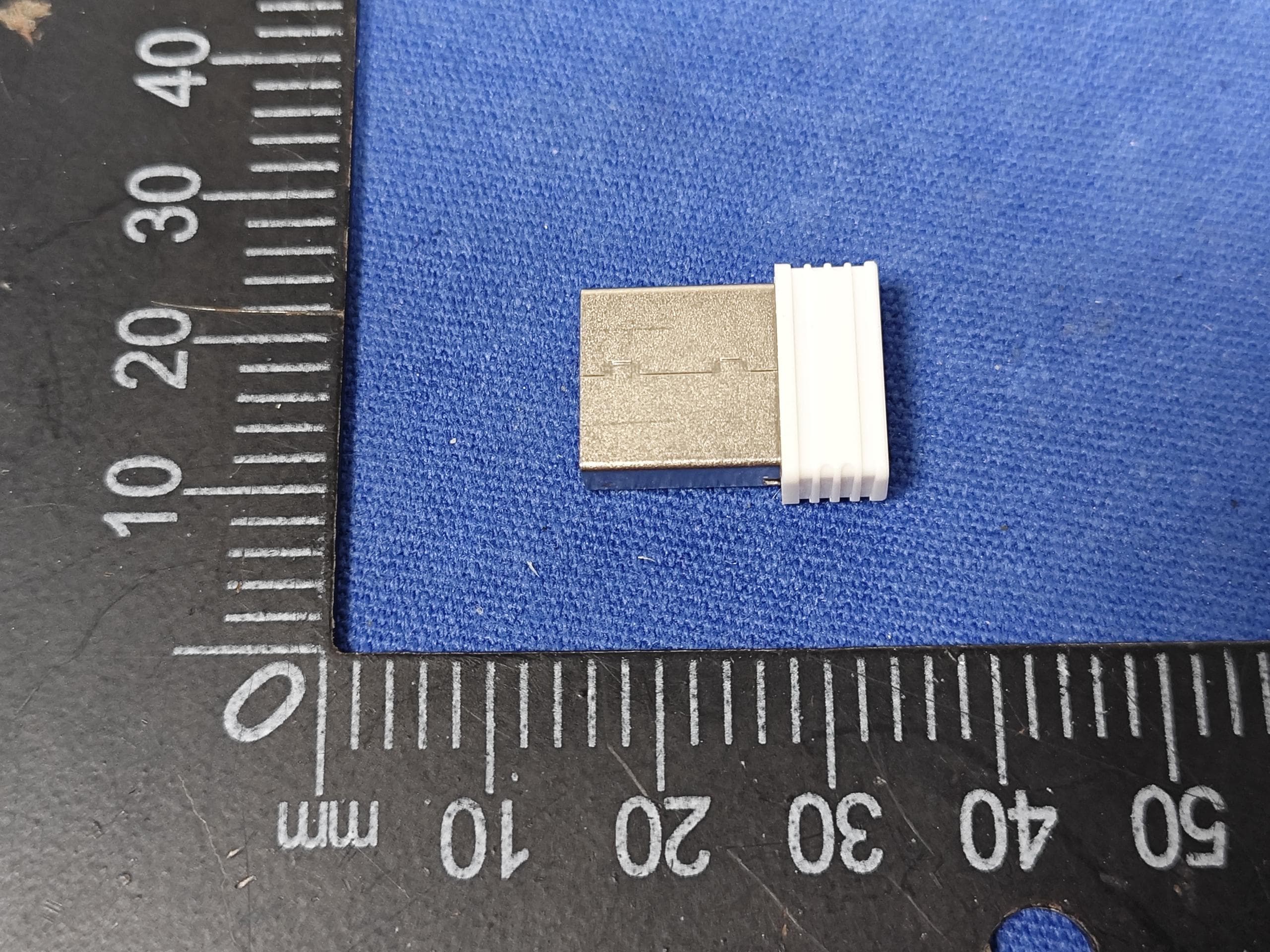
Z63-O6K98PROUSB
Mar 23, 2026WIRELESS MECHANICAL KEYBOARD-USB RECEIVER
Equipment Class
DTS - Digital Transmission System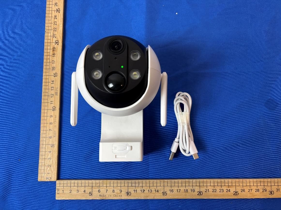
Z63-EL02302
Dec 15, 2025Smart Battery Wireless P/T Camera
Equipment Class
DTS - Digital Transmission System
Z63-ER02301
Nov 23, 2025Smart Battery Doorbell Camera
Equipment Class
DTS - Digital Transmission System
Z63-O5MATE98
Sep 22, 2025WIRELESS MECHANICAL KEYBOARD
Equipment Class
DTS - Digital Transmission System