Z63-E95ASmart Wireless P&T Camera
SHENZHEN AONI ELECTRONIC CO., LTD.
Click to zoom
Application Details
- Equipment Class
- DTS - Digital Transmission System
- Date of Grant
- Sep 23, 2020
- Application Purpose
- Original Equipment
- Date of Application
- Sep 23, 2020
- Equipment Note
- Smart Wireless P&T Camera
- Frequency Range
- 2412.00000000 - 2462.00000000
- Country
- China
Documents & Files
Document Text
Text extracted from the exhibit documents filed with the FCC. Open a document above to read the original.
Users Manual
Quick Start Guide Smart Wireless P/T Camera Model: E95A Welcome Thank you for choosing our smart camera. Getting started is easy. What’s Included Security Camera Bracket (Optional) Power Adapter USB Cable Product Details 1. Connection Preparation Bring the camera and phone within 1 to 3 feet (30 to 100 centimeters) of the router. Router 30cm~100cm Camera Smartphone Note: Make sure smart phone is connected with your wireless router. Please note the camera is only working under 2.4G Wi-Fi, not support 5G Wi-Fi. For the best experience, please download the "Tuya smart" APP to your smartphone from App Store or Google Play, or you can also scan the QR code below, the APP icon will be displayed after installed successfully. 2. Get the APP and Account Launch the app from your smartphone and click the Sign Up button. Follow the on-screen instructions. You can place your camera on a shelf or other flat surface, or you can mount it to the wall. To mount your camera to the wall: 6. Place or Mount Your Camera Connect the power to the camera by Micro USB Power Adapter. (DC5V/1.5A) 4. Connect the power to the camera Fasten the mounting screw into the wall, and then mount the camera from the screw. If you’re mounting the camera to drywall, be sure the plastic drywall anchors that are provided. You’re done! Congratulations! Your camera is set up and ready to go. All trademarks are used for reference purposes only. Thanks again for choosing our smart camera! Makelife safe in your hands! Boost security mobility in your smartphone! Appendix: Camera LED Guide NO.LED StatusCamera Status 1System starting upRed LED on 2Standby for configurationRed LED blinks quickly 3Network pairingBlue LED blinks quickly 4Camera onlineBlue LED on 5 OTA upgrade Red LED blinks slowly Wall Mount Screw Sets (Optional) Light sensor Power interface Lens Infrared lights Microphone Speaker Mounting Hole MicroSD card Reset Insert the Micro SD card gently on the side edge of camera. 3. Insert the Micro SD card Press the Reset button for above 5 seconds, then release the button to reset the camera, then the LED light will blink quickly. Click "Add Device" or "+" on the right corner to add device; Then click " Security&Sensor" to select" Smart Camera" 5. Set up your camera Follow the App's instructions and input the right wifi password; Point the QR code to the camera lens for 15-20cm ; Click"HEARD THE BEEP" when you heard "dingding". After processing, it paired successfully. The blue light is on, camera is ready for viewing. Smart Wireless P/T Camera Quick Start Guide Quick Start Guide Model: E95A Tuya Smart Tuya Smart Press the Reset button for above 5 seconds Blue LED blinks FCC Warning This device complies with part 15 of the FCC Rules. Operation is subject to the following two conditions: (1) This device may not cause harmful interference, and (2) this device must accept any interference received, including interference that may cause undesired operation. Any Changes or modifications not expressly approved by the party responsible for compliance could void the user's authority to operate the equipment. Note: This equipment has been tested and found to comply with the limits for a Class B digital device, pursuant to part 15 of the FCC Rules. These limits are designed to provide reasonable protection against harmful interference in a residential installation. This equipment generates uses and can radiate radio frequency energy and, if not installed and used in accordance with the instructions, may cause harmful interference to radio communications. However, there is no guarantee that interference will not occur in a particular installation. If this equipment does cause harmful interference to radio or television reception, which can be determined by turning the equipment off and on, the user is encouraged to try to correct the interference by one or more of the following measures: -Reorient or relocate the receiving antenna. -Increase the separation between the equipment and receiver. -Connect the equipment into an outlet on a circuit different from that to which the receiver is connected. -Consult the dealer or an experienced radio/TV technician for help. This equipment complies with FCC radiation exposure limits set forth for an uncontrolled environment. This equipment should be installed and operated with minimum distance 20cm between the radiator & your body.
Cover Letter(s)
QF094234 Page 1 of 1 Revision 0 Authority to Act as Agent Date: 2020-09-18 TUV Rheinland Group 762 Park Avenue Youngsville, NC 27596 To Whom It May Concern: I appoint TUV Rheinland (Shenzhen) Co., Ltd. to act as our agent in the preparation of this application for equipment certification. I certify that submitted documents properly describe the device or system for which equipment certification is sought. I also certify that each unit manufactured, imported or marketed, as defined in the FCC or Industry Canada’s regulations will have affixed to it a label identical to that submitted for approval with this application. For instances where our authorized agent signs the application for certification on our behalf, I acknowledge that all responsibility for complying with the terms and conditions for Certification, as specified by TUV Rheinland Group, still resides with ShenZhen Aoni Electronic Industry Co., Ltd. / HongHui Industrial Park,2nd LiuXian Road, Xin'An streets, District 68, Bao'an District, ShenZhen, China For TCB applications, We certify that we are not subject to denial of federal benefits, that includes FCC benefits, pursuant to Section 5301 of the Anti-Drug Abuse Act of 1988, 21 U.S.C. 862. Further, no party, as defined in 47 CFR 1.2002 (b), to the application is subject to denial of federal benefits, that includes FCC benefits. Thank you, Agency Agreement Expiration Date: 12 months By : tendy Dong (Signature) (Print Name) Title : Manager Telephone : 0755-29106235 On behalf of : ShenZhen Aoni Electronic Industry Co., Ltd. (Company Name) ShenZhen Aoni Electronic Industry Co., Ltd.
Cover Letter(s)
Confidentiality Letter Date: 2020-09-18 Subject: Confidentiality Request forFCC ID: Z63-E9 Pursuant to FCC 47 CRF 0.457(d) and 0.459 and IC RSP-100, Section 10, the applicant requests that a part of the subject FCC/IC application be held confidential. Type of Confidentiality Requested Exhibit Short Term Permanent Block Diagrams Short Term External Photos Short Term Permanent Internal Photos Short Term Permanent Operation Description/Theory of Operation Short Term Permanent Part List/Tune-Up Procedure Short Term Permanent Schematics Short Term Test Setup Photos Short Term Permanent anual Superior Communications has spent substantial effort in developing this product and it is one of the first of its kind in industry. Having the subject information easily available to "competition" would negate the advantage they have achieved by developing this product. Not protecting the details of the design will result in financial hardship. Permanent Confidentiality: The applicant requests the exhibits listed above as permanently confidential be permanently withheld from public review due to materials that contain trade secrets and proprietary information not customarily released to the public. Short-Term Confidentiality: The applicant requests the exhibits selected above as short term confidential be withheld from public view for a period of 180days from the date of the Grant of Equipment Authorization and prior to marketing. This is to avoid premature release of sensitive information prior to marketing or release of the product to the public. Applicant is also aware that they are responsible to notify TUV Rheinland in the event information regarding the product or the product is made available to the public. TUV Rheinland will then release the documents listed above for public disclosure pursuant to FCC Public Notice DA 04- 1705. Sincerely, ShenZhen Aoni Electronic Industry Co., Ltd. By: tendy Dong (Signature/Title) (Print name)
External Photos
Page 1 of 8 Report No.: STS2009013 APPENDIX-PHOTOGRAPHS OF EUT CONSTRUCTIONAL DETAILS Model: E95A Photo 1 Photo 2 Page 2 of 8 Report No.: STS2009013 Photo 3 Photo 4 Page 3 of 8 Report No.: STS2009013 Photo 5 Photo 6 Page 4 of 8 Report No.: STS2009013 Photo 7 Photo 8 Page 5 of 8 Report No.: STS2009013 Photo 9 Photo 10 Page 6 of 8 Report No.: STS2009013 Photo 11 Photo 12 Page 7 of 8 Report No.: STS2009013 Photo 13 Photo 14 Page 8 of 8 Report No.: STS2009013 Photo 15
ID Label/Location Info
FCC Label The label is printed on the shell Smart Wireless P&T Camera Model name: E95A FCC ID: Z63-E95A
Internal Photos
Page 1 of 5 Report No.: STS2009013 APPENDIX-PHOTOGRAPHS OF EUT CONSTRUCTIONAL DETAILS Model: E95A Photo 1 Photo 2 Page 2 of 5 Report No.: STS2009013 Photo 3 Photo 4 Page 3 of 5 Report No.: STS2009013 Photo 5 Photo 6 WIFI Antenna Page 4 of 5 Report No.: STS2009013 Photo 7 Photo 8 Page 5 of 5 Report No.: STS2009013 Photo 9 Photo 10
RF Exposure Info
RF Exposure Report FCC ID: Z63-E95A RF Exposure Measurement The limit for Maximum Permissible Exposure (MPE) specified in FCC 1.1310 is followed. The gain of the antennas used in the product is extracted from the Antenna data sheets provided and also the maximum total power input to the antenna is measured. Through the Friis transmission formula and the maximum gain of the antenna, we can calculate the distance, away from the product, where the limit of MPE is reached. Although the Friis Transmission formula is far field assumption, the calculated result of that is an over-prediction for near field power density. It is taken as worst case to specify the safety range. RF Exposure Limit According to FCC 1.1310: The criteria listed in the following table shall be used to evaluate the environmental impact of the human exposure to radio-frequency (RF) radiation as specified in 1.1307 (b) Limits for Maximum Permissible Exposure (MPE) F= Frequency in MHz Frequency Range (MHz) Electric Field Strength (V/m) Magnetic Field Strength (A/m) Power Density (mW/cm²) Limits for Occupational / controlled Exposures 300 - 1500 -- -- F/300 1500 – 100000 -- -- 5.0 Limits for General population / Uncontrolled Exposure 300 - 1500 -- -- F/1500 1500 – 100000 -- -- 1.0 Friss Formula Friss Transmission Formula: Pd = (Pout * G) / (4*pi*r²) Where Pd = power density in mW/cm² Pout = output power to antenna in mW G = gain of antenna in linear scale Pi = 3.1416 R = Distance between observation point and the center of radiator in cm If we know the maximum gain of the antenna and the total output power to the antenna, through calculation, we will know MPE value at distance 20cm. EUT Operation condition EUT was enabled to transmit and receive at lowest, middle and highest channels. Classification The antenna of this product, under normal use condition, is at least 20cm away from the body of the user. Warning statement to the user for keeping at least 20cm or more separation distance from the antenna should be included in the User manual. So, this device is classified as Mobile device. 2.4G WIFI Mode 802.11b/g/n20:2412-2462MHz Detector PEAK 802.11b CH01 13±1dBm 802.11b CH06 11±1dBm 802.11b CH11 10±1dBm 802.11g CH01 20±1dBm 802.11g CH06 16±1dBm 802.11g CH11 14±1dBm 802.11n20 CH01 20±1dBm 802.11n20 CH06 18±1dBm 802.11n20 CH11 16±1dBm 802.11n40 CH03 18±1dBm 802.11n40 CH06 17±1dBm 802.11n40 CH09 17±1dBm ANT Gain (G) Antenna gain : 3dBi (gain of antenna in linear scale=1.995) Protocol ANT Gain(gain of antenna in linear scale) Channel Frequency (MHz) Output Power to Antenna (dBm) Output Power to Antenna (mW) Power Density (mW/cm²) Limit (mW/cm²) 802.11b CH01 1.995 2412 14 25.118864 0.0099695 1 802.11b CH06 1.995 2437 12 15.848932 0.0062903 1 802.11b CH11 1.995 2462 11 12.589254 0.0049966 1 802.11g CH01 1.995 2412 21 125.89254 0.0499657 1 802.11g CH06 1.995 2437 17 50.118723 0.0198917 1 802.11g CH11 1.995 2462 15 31.622777 0.0125508 1 802.11n20 CH01 1.995 2412 21 125.89254 0.0499657 1 802.11n20 CH06 1.995 2437 19 79.432823 0.0315262 1 802.11n20 CH11 1.995 2462 17 50.118723 0.0198917 1 802.11n40 CH03 1.995 2422 19 79.432823 0.0315262 1 802.11n40 CH06 1.995 2437 18 63.095734 0.0250422 1 802.11n40 CH09 1.995 2452 18 63.095734 0.0250422 1 According to the maximum gain of the antenna and the total output power to the antenna, through calculation, we will know MPE value 0.0499657 at distance 20cm. This is less than the limit 1, so the Compliance the RF exposure requirement.
Test Report
Page 1 of 2 FCC ID: Z63-E95A DTS Setup photo Model name: E95A DTS conduction DTS radiation L Page 2 of 2 FCC ID: Z63-E95A DTS radiation H
Test Setup Photos
Any reproduction of this document must be done in full. No single part of this document may be reproduced without permission from STS, All Test Data Presented in this report is only applicable to presented Test sample. Shenzhen STS Test Services Co., Ltd. A 1/F, Building B, Zhuoke Science Park, No.190 Chongqing Road, HepingShequ, Fuyong Sub-District, Bao’an District, Shenzhen, Guang Dong, China TEL: +86-755 3688 6288 FAX: +86-755 3688 6277 E-mail:[email protected] RADIO TEST REPORT Report No.:STS2009013W03 Issued for ShenZhen Aoni Electronic Industry Co., Ltd. HongHui Industrial Park,2nd LiuXian Road, Xin'An streets, District 68, Bao'an District, ShenZhen, China Product Name: Smart Wireless P&T Camera Brand Name: N/A Model Name: E95A Series Model: E95AR7C, E953, E953R7C FCC ID: Z63-E95A Test Standard: FCC Part 15.247 S T L A B S S T L A B S Page 2 of 68 Report No.:STS2009013W03 TEST RESULT CERTIFICATION Applicant’s Name ................. : ShenZhen Aoni Electronic Industry Co., Ltd. Address ................................. : HongHui Industrial Park,2nd LiuXian Road, Xin'An streets, District 68, Bao'an District, ShenZhen, China Manufacturer's Name ........... : ShenZhen Aoni Electronic Industry Co., Ltd. Address ................................. : HongHui Industrial Park,2nd LiuXian Road, Xin'An streets, District 68, Bao'an District, ShenZhen, China Product Description Product Name ........................ : Smart Wireless P&T Camera Brand Name ........................... : N/A Model Name .......................... : E95A Series Model .......................... : E95AR7C, E953, E953R7C Test Standards ..................... : FCC Part15.247 Test Procedure........................: ANSI C63.10-2013 This device described above has been tested by STS, the test results show that the equipment under test (EUT) is in compliance with the FCC requirements. And it is applicable only to the tested sample identified in the report. This report shall not be reproduced except in full, without the written approval of STS, this document only be altered or revised by STS, personal only, and shall be noted in the revision of the document. Date of Test ........................................... : Date of receipt of test item ...................... : 02 Sept. 2020 Date (s) of performance of tests ............. : 02 Sept. 2020 ~ 10 Sept. 2020 Date of Issue .......................................... : 10 Sept. 2020 Test Result .............................................. : Pass Testing Engineer : (Chris Chen) Technical Manager : (Sean she) Authorized Signatory : (Vita Li) Page 3 of 68 Report No.:STS2009013W03 Table of Contents Page 1. SUMMARY OF TEST RESULTS 6 1.1 TEST FACTORY 7 1.2 MEASUREMENT UNCERTAINTY 7 2. GENERAL INFORMATION 8 2.1 GENERAL DESCRIPTION OF THE EUT 8 2.2 DESCRIPTION OF THE TEST MODES 10 2.3 TEST SOFTWARE AND POWER LEVEL 10 2.4 BLOCK DIAGRAM SHOWING THE CONFIGURATION OF SYSTEM TESTED 11 2.5 DESCRIPTION OF NECESSARY ACCESSORIES AND SUPPORT UNITS 12 2.6 EQUIPMENTS LIST FOR ALL TEST ITEMS 13 3. EMC EMISSION TEST 14 3.1 CONDUCTED EMISSION MEASUREMENT 14 3.2 RADIATED EMISSION MEASUREMENT 18 4. CONDUCTED SPURIOUS & BAND EDGE EMISSION 30 4.1 LIMIT 30 4.2 TEST PROCEDURE 30 4.3 DEVIATION FROM STANDARD 30 4.4 TEST SETUP 30 4.5 EUT OPERATION CONDITIONS 30 4.6 TEST RESULTS 31 5. POWER SPECTRAL DENSITY TEST 47 5.1 LIMIT 47 5.2 TEST PROCEDURE 47 5.3 DEVIATION FROM STANDARD 47 5.4 TEST SETUP 47 5.5 EUT OPERATION CONDITIONS 47 5.6 TEST RESULTS 48 6. BANDWIDTH TEST 56 6.1 LIMIT 56 6.2 TEST PROCEDURE 56 6.3 DEVIATION FROM STANDARD 56 6.4 TEST SETUP 56 6.5 EUT OPERATION CONDITIONS 56 Page 4 of 68 Report No.:STS2009013W03 Table of Contents Page 6.6 TEST RESULTS 57 7. PEAK OUTPUT POWER TEST 65 7.1 LIMIT 65 7.2 TEST PROCEDURE 65 7.3 DEVIATION FROM STANDARD 65 7.4 TEST SETUP 65 7.5 EUT OPERATION CONDITIONS 65 7.6 TEST RESULTS 66 8. ANTENNA REQUIREMENT 67 8.1 STANDARD REQUIREMENT 67 8.2 EUT ANTENNA 67 APPENDIX-PHOTOS OF TEST SETUP 68 Page 5 of 68 Report No.:STS2009013W03 Revision History Rev. Issue Date Report No. Effect Page Contents 00 10 Sept. 2020 STS2009013W03 ALL Initial Issue Page 6 of 68 Report No.:STS2009013W03 1. SUMMARY OF TEST RESULTS Test procedures according to the technical standards: KDB 558074 D01 15.247 Meas Guidance v05r02. FCC Part 15.247,Subpart C Standard Section Test Item Judgment Remark 15.207 Conducted Emission PASS -- 15.247 (a)(2) 6dB Bandwidth PASS -- 15.247 (b)(3) Output Power PASS -- 15.247 (c) Radiated Spurious Emission PASS -- 15.247 (d) Conducted Spurious & Band Edge Emission PASS -- 15.247 (e) Power Spectral Density PASS -- 15.205 Restricted Band Edge Emission PASS -- Part 15.247(d)/part 15.209(a) Band Edge Emission PASS -- 15.203 Antenna Requirement PASS -- NOTE: (1) ‘N/A’ denotes test is not applicable in this Test Report. (2) All tests are according to ANSI C63.10-2013. Page 7 of 68 Report No.:STS2009013W03 1.1 TEST FACTORY SHENZHEN STS TEST SERVICES CO., LTD Add. : A 1/F, Building B, Zhuoke Science Park, No.190 Chongqing Road, HepingShequ, Fuyong Sub-District, Bao’an District, Shenzhen, Guang Dong, China FCC test Firm Registration Number: 625569 IC test Firm Registration Number: 12108A A2LA Certificate No.: 4338.01 1.2 MEASUREMENT UNCERTAINTY The reported uncertainty of measurement y ±U, where expended uncertainty U is based on a standard uncertainty multiplied by a coverage factor of k=2, providing a level of confidence of approximately 95 %. No. Item Uncertainty 1 RF output power, conducted ±0.68dB 2 Unwanted Emissions, conducted ±2.988dB 3 All emissions, radiated 30-1GHz ±5.6dB 4 All emissions, radiated 1G-6GHz ±5.5dB 5 All emissions, radiated>6G ±5.8dB 6 Conducted Emission (9KHz-150KHz) ±3.37dB 7 Conducted Emission (150KHz-30MHz) ±3.83dB Page 8 of 68 Report No.:STS2009013W03 2. GENERAL INFORMATION 2.1 GENERAL DESCRIPTION OF THE EUT Product Name Smart Wireless P&T Camera Trade Name N/A Model Name E95A Series Model E95AR7C, E953, E953R7C Model Difference E95AR7C and E95A Only th…
Text truncated - open the document above for the full version.
Contact Information
Applicant
tendy Dong
Test Firm
SHENZHEN STS TEST SERVICES CO.,LTD.Bovey Yang
[email protected]+86 755-36886288
Technical Specifications
| # | Rule Parts | Frequency Range | Power Output |
|---|---|---|---|
| 1 | 15C | 2.41 GHz - 2.46 GHz | 103.00 mW |
Other Applications from SHENZHEN AONI ELECTRONIC CO., LTD.
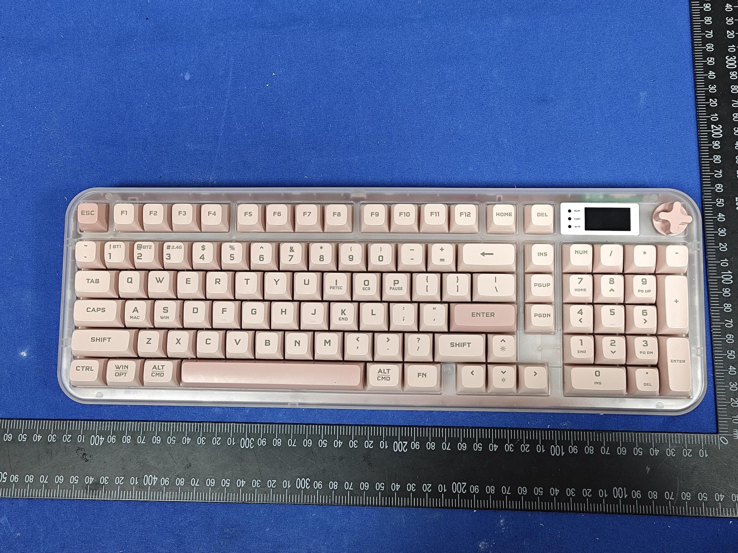
Z63-O6K98PRO
Mar 23, 2026Wireless Triple-Mode Keyboard
Equipment Class
DTS - Digital Transmission System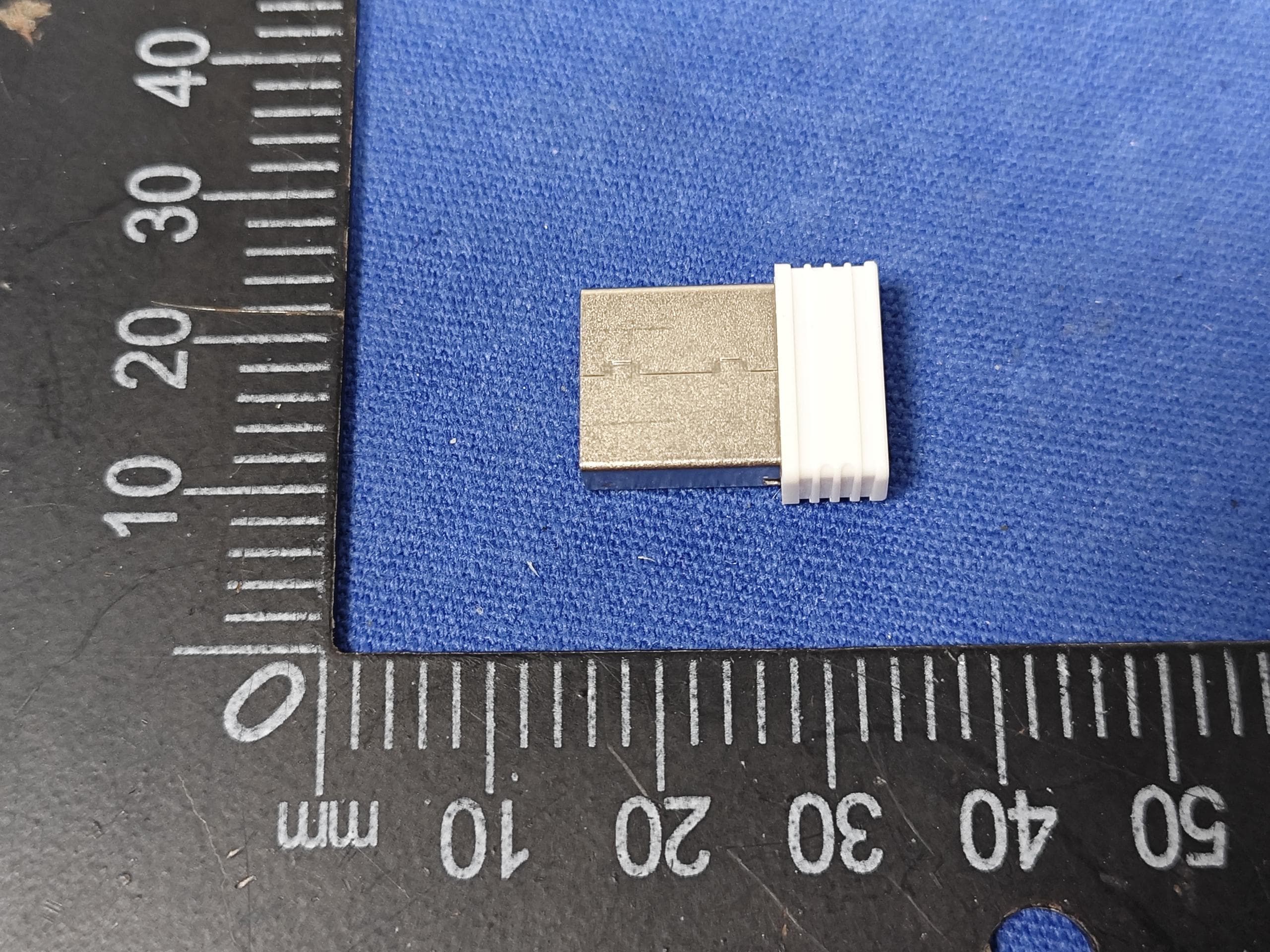
Z63-O6K98PROUSB
Mar 23, 2026WIRELESS MECHANICAL KEYBOARD-USB RECEIVER
Equipment Class
DTS - Digital Transmission System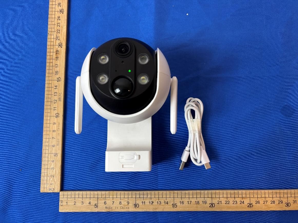
Z63-EL02302
Dec 15, 2025Smart Battery Wireless P/T Camera
Equipment Class
DTS - Digital Transmission System
Z63-ER02301
Nov 23, 2025Smart Battery Doorbell Camera
Equipment Class
DTS - Digital Transmission System
Z63-O5MATE98
Sep 22, 2025WIRELESS MECHANICAL KEYBOARD
Equipment Class
DTS - Digital Transmission System