Z7KWP0082011Probe Radio Board
Dwyer Instruments, Inc.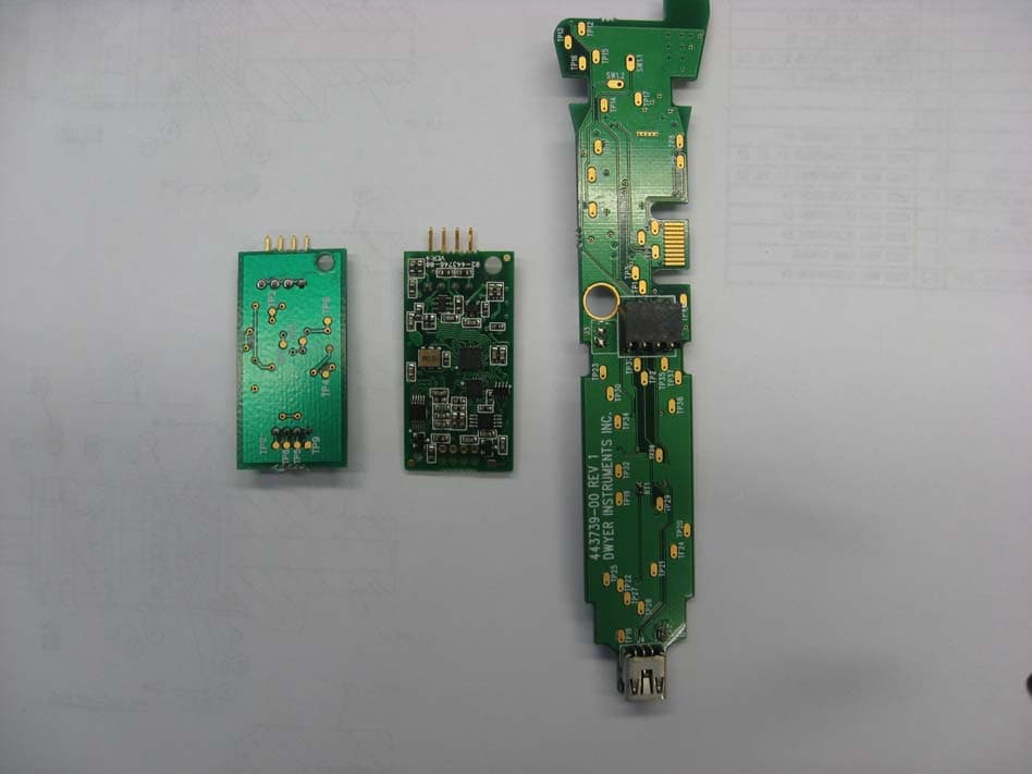
Click to zoom
Application Details
- Equipment Class
- DTS - Digital Transmission System
- Date of Grant
- Nov 07, 2011
- Application Purpose
- Original Equipment
- Date of Application
- Nov 07, 2011
- Equipment Note
- Probe Radio Board
- Frequency Range
- 2405.00000000 - 2480.00000000
- Company
- Dwyer Instruments, Inc.
- Country
- United States
Documents & Files
Document Text
Text extracted from the exhibit documents filed with the FCC. Open a document above to read the original.
Block Diagram
ATMEGA88PA-AU Freescale MC13224V 24 MHz crystal 8 MHz crystal Sensor Interface USB connection Li Ion Poly Battery Serial Serial Power SupplyAntenna 3.3V 5V 5V 3.3V Control Dwyer Instruments Probe Radio Board (PRB) Block Diagram Battery Charging Circuit Power Button 5V
Cover Letter(s)
Page 1 of 1 RP-6XXXL 12 East Devonwood SOLVING A WAVE OF EMI COMPLIANCE PROBLEMS Romeoville, IL 60446 August 29, 2011 Tel: (815) 293-0772 Page 1 of 1 Fax: (815) 293-0820 Federal Communications Commission Authorization and Evaluation Division 7435 Oakland Mills Rd. Columbia, MD 21046 Industry Canada Certification and Engineering Bureau Ottawa, Ontario K2H 8S2 Canada Reference FCC ID: Z7KWP0082011 Reference IC: 9525A-WP82011 Organization: Dwyer Instruments, Inc.. 2. Long Term Confidentiality Dwyer Instruments requests that the following materials be withheld from public inspection permanently under 47 C.F.R. 0.457 & 0.459: (1) Detailed Circuit Schematics of the EUT The above materials contain proprietary and confidential information not customarily released to the public. The public disclosure of these materials provides unjustified benefits to its competitors in the market. They are considered confidential trade secrets Authorized Signature Joseph Strzelecki Senior EMC Engineer Radiometrics Midwest Corporation Authorized Agent for Dwyer Instruments, Inc.
Cover Letter(s)
Page 1 of 2 RP-6951B 12 East Devonwood SOLVING A WAVE OF EMI COMPLIANCE PROBLEMS Romeoville, IL 60446 Tel: (815) 293-0772 Fax: (815) 293-0820 Federal Communications Commission Authorization and Evaluation Division APPLICANT: Dwyer Instruments, Inc. REFERENCE FCC ID: ZK7WP0082011 IC: 9525A-WP82011 RE: Request for Limited Modular Approval Modular approval Requirements Characteristics Item Requirement EUT Justification 1 Have its own RF shielding The RF portions of the module are not contained within a metal shielding can. The approval request is for a Limited Modular Approval. 2 Have buffered modulation/data inputs (if such inputs are provided), There is a serial input that is buffered via a UHS tri state buffer NC7SZ126M5X from Fairchild. 3 Have it own power supply regulation The module has a regulated power supply. The module will be installed in a product that has a self contained rechargeable battery and regulated power supply. 4 Meet the antenna requirements of Section 15.203 The antenna is a soldered electronic component that is surface mounted to the circuit board. 5 Be tested in a stand-alone configuration, i.e., the antenna, AC or DC power and data input/output lines must be connected to the module but, the module must not be inside another case during testing The module was tested in a handheld assembly. The assembly has a plastic housing and provides power. This is its only approved configuration. 6 Be labeled with its own FCC ID number, and if the FCC ID is not visible when the module is installed inside another device, then the outside of the device into which the module is installed must also display a label referring to the enclosed module. The ID label format is included in the filing. The label will be on the module and the exterior of the product. 7 The modular transmitter is manufactured so that the user cannot influence the operation of the transmitter that will operate outside of the scope of the regulations. The Device is programmed during manufacture to operate at a given approved frequency and power level. Programming connection is internal to the device and requires a dedicated programmer with a unique connector and pin out. Page 2 of 2 RP-6951B Item Requirement EUT Justification 8 Address compliance with the Commission's RF exposure limits in Sections 1.1310 and 2.1093. In addition, spread spectrum transmitters operating under Section 15.247 are required to address RF exposure compliance in accordance with Section 15.247(b)(4). Refer to RF exposure Exhibit. The transmitter meets MPE calculations of 47 CFR 1.1310. General information for Limited Modular Approval The WP0082011 radio probe board is seeking FCC limited modular approval. The circuit board is a sub- assembly that is added to a data measurement probe to give it wireless functionality. The data measurement probe consists of a sensor assembly, a sensor main board and a cable used to plug into the data collection device. When the WP0082011 is added to the data measurement probe it replaces the cable and becomes the interface to the data collection device. The sensor main board plugs directly into the WP0082011 and passes the data measured to the radio probe board which then transmits the data to the data collection device. The radio probe board can only be used with Dwyer developed data measurement probes such as the AP2, thermo anemometer air velocity and temperature probe or the RP2, thermo hygrometer humidity and temperature probe. Therefore, the WP0082011 radio probe board is exclusive to the Dwyer product line and consequentially tightly controlled by Dwyer Instruments. The interface between the sensor main board and the radio probe board is a simple serial and power connection that is consistent for all sensor assemblies that accept the radio probe board. The unique form factor of the radio probe board is only compatible with Dwyer designed and manufactured data measurement probes and therefore cannot be utilized in products not manufactured by Dwyer Instruments. Only the Dwyer Instruments data collection device (UHH) can communicate with the firmware on board the radio probe board to gather the data captured by the data measurement probe. Thusly, the radio probe board is only functional in a Dwyer Instruments designed and manufactured system or device. The module will only be installed in Dwyer AQTIP pro series products. Please do not hesitate to contact me if there are any further questions with the submittal. Sincerely, Joseph Strzelecki, NCE Radiometrics Midwest Corporation Authorized Agent for Dwyer Instruments, Inc. E-Mail: [email protected] Radiometrics has been authorized by Dwyer Instruments, Inc. to act as an agent in the preparation of their submittal request for Limited Modular Approval.
External Photos
Authorized Agent: Radiometrics Midwest Corporation (815) 293-0772 EUT Photographs The module is the long board. This contains all of the RF circuitry. The small board is the sensor board. Authorized Agent: Radiometrics Midwest Corporation (815) 293-0772 Authorized Agent: Radiometrics Midwest Corporation (815) 293-0772 Full system
ID Label/Location Info
Authorized Agent: Radiometrics Midwest Corporation (815) 293-0772 ID Label/Location Label Drawings Module Label Radiometrics Midwest Corporation (815) 293-0772 – [email protected] External Label Location of Label Location of Label on Module Note that the lettering on the photo is not the final letters used. The drawing on page 1 of this document shows the final wording. This is the final location. Radiometrics Midwest Corporation (815) 293-0772 – [email protected] External Label Location Outer case Note that the lettering on the photo is not the final letters used. The drawing on page 2 of this document shows the final wording. This is the final location.
Internal Photos
Authorized Agent: Radiometrics Midwest Corporation (815) 293-0772 Internal EUT Photographs The module is the long board. This contains all of the RF circuitry. The small board is the sensor board. Authorized Agent: Radiometrics Midwest Corporation (815) 293-0772 Authorized Agent: Radiometrics Midwest Corporation (815) 293-0772 Full system
Operational Description
Authorized Agent: Radiometrics Midwest Corporation (815) 293-0772 Product Description The product is a hand held data measurement probe radio communications board. When used in conjunction with a data measurement probe it wirelessly communicates and downloads data to a handheld device for data viewing and storage. In particular, as part of an AP2 the unit measures air velocity and temperature and in the case of a RP2 the unit measures humidity and temperature. The targeted market is commercial/industrial for the purpose of collecting data such as humidity, temperature, air speed, and pressure. When combined with the Universal Handheld test instrument (UHH) for data download and viewing they comprise a single data measurement instrument. The wireless communication protocol is Zigbee operating at 2.4GHz on the IEEE 802.15.4 physical radio specification. The transmission technology is Direct Sequence Spread Spectrum (DSSS) with 250 kbps Offset-Quadrature Phase Shift Keying (OQPSK), which is used to build a mesh network incorporating the device and its associated wireless sensor probes. The antenna is a soldered electronic component surface mounted to the printed circuit board internal to the device. It cannot be removed without de-soldering tools. No other antennas are required for the device to operate. Device is powered via an internal rechargeable battery. Modular approval information: The WP0082011 radio probe board is seeking FCC modular approval. The circuit board is a sub- assembly that is added to a data measurement probe to give it wireless functionality. The data measurement probe consists of a sensor assembly, a sensor main board and a cable used to plug into the data collection device. When the WP0082011 is added to the data measurement probe it replaces the cable and becomes the interface to the data collection device. The sensor main board plugs directly into the WP0082011 and passes the data measured to the radio probe board which then transmits the data to the data collection device. The radio probe board can only be used with Dwyer developed data measurement probes such as the AP2, thermo anemometer air velocity and temperature probe or the RP2, thermo hygrometer humidity and temperature probe. Therefore, the WP0082011 radio probe board is exclusive to the Dwyer product line and consequentially tightly controlled by Dwyer Instruments. The interface between the sensor main board and the radio probe board is a simple serial and power connection that is consistent for all sensor assemblies that accept the radio probe board. The unique form factor of the radio probe board is only compatible with Dwyer designed and manufactured data measurement probes and therefore cannot be utilized in products not manufactured by Dwyer Instruments. Only the Dwyer Instruments data collection device (UHH) can communicate with the firmware on board the radio probe board to gather the data captured by the data measurement probe. Thusly, the radio probe board is only functional in a Dwyer Instruments designed and manufactured system or device. The module will only be installed in Dwyer AQTIP pro series products.
RF Exposure Info
Authorized Agent: Radiometrics Midwest Corporation (815) 293-0772 RF Exposure This calculation is based on the highest EIRP possible from the EUT considering maximum power and antenna gain. The highest effective output power of the EUT is 0.9 mW 1 MINIMUM SEPARATION DISTANCE PER OET 65 The following information provides the minimum separation distance for the EUT, as calculated from FCC OET 65 Appendix B, Table 1B “Guidelines for General Population/Uncontrolled Exposure” SMaximum AntennaMSD Freq.GP limitRF power GainEIRPEIRPd MHzmW/cm^2 dBmdBdBmwattsmeters 24501-0.20-0.20.0010 0.0028 GP is the limit for general Population/Uncontrolled Exposure MSD is the minimum Seperation Distance Notes on above table. (S) GP limit is from OET 65 table 1B EIRP = Power in dBm + Antenna Gain in dBi MSD (Minimum Separation Distance) = ((EIRP*30)/3770*S))^0.5 NOTE: For mobile or fixed location transmitters, minimum separation distance is 20 cm, even if calculations indicate MPE distance is less The low threshold for a device operated within 2.5 cm from human body is 60/(f GHz) = 60/2.440 = 24.59 mw Since this device has a power which is lower than 24.59 mw, no SAR is required. 2 RF EVAULATION FOR RSS-102E Since the e.i.r.p. of the Product is 0.9 mW, it is exempt from routine SAR and RF exposure evaluations in accordance to Sections 2.5.1 or 2.5.2 of RSS-102e.
Test Report
Radiometrics Midwest Corporation - www.Radiomet.com Page 1 of 25 Electromagnetic Compatibility Test Report Tests Performed on a Dwyer Instruments Probe Radio Board Module Model PRB Radiometrics Document RP-6951B Product Detail: FCC ID: Z7KWP0082011 IC ID: 9525A-WP82011 Equipment type: DTS, 2.4 GHz transmitter Test Standards: US CFR Title 47, Chapter I, FCC Part 15 Subpart C FCC Part 15 CFR Title 47: 2009 Industry Canada RSS-210, Issue 8: 2010 as required for Category I Equipment This report concerns: Original Grant for Certification FCC Part 15.247 Tests Performed For: Test Facility: Dwyer Instrument, Inc. 102 Indiana Hwy. 212 Michigan City, IN 46361 Radiometrics Midwest Corporation 12 East Devonwood Romeoville, IL 60446 (815) 293-0772 Test Date(s): (Month-Day-Year) March 23 to August 5, 2011 Document RP-6951B Revisions: Rev. Issue Date Affected Sections Revised By 0 September 12, 2011 1 September 15, 2011 All Joseph Strzelecki 2 October 27, 2011 Pages 1 and 4 Joseph Strzelecki Radiometrics Midwest Corporation www.radiomet.com Testing of the Dwyer, Model PRB, PRB Module in a Universal Temperature Amemometer RP-6951B Rev. 1 Page 2 of 25 Table of Contents 1 ADMINISTRATIVE DATA.................................................................................................................... 3 2 TEST SUMMARY AND RESULTS......................................................................................................3 2.1 RF Exposure Compliance Requirements ..................................................................................... 4 3 EQUIPMENT UNDER TEST (EUT) DETAILS..................................................................................... 4 3.1 EUT Description............................................................................................................................ 4 3.1.1 FCC Section 15.203 & RSS-GEN Antenna Requirements .................................................... 4 3.2 Related Submittals........................................................................................................................ 4 4 TESTED SYSTEM DETAILS .............................................................................................................. 4 4.1 Tested System Configuration ....................................................................................................... 4 4.2 Special Accessories...................................................................................................................... 5 4.3 Equipment Modifications............................................................................................................... 5 5 TEST SPECIFICATIONS AND RELATED DOCUMENTS .................................................................. 5 6 RADIOMETRICS’ TEST FACILITIES.................................................................................................. 5 7 DEVIATIONS AND EXCLUSIONS FROM THE TEST SPECIFICATIONS ......................................... 6 8 CERTIFICATION ................................................................................................................................. 6 9 TEST EQUIPMENT TABLE ................................................................................................................ 6 10 TEST SECTIONS .............................................................................................................................. 7 10.1 AC Conducted Emissions ........................................................................................................... 7 10.2 Time of Occupancy (Dwell Time).............................................................................................. 10 10.3 Occupied Bandwidth ................................................................................................................. 10 10.4 Peak Output Power................................................................................................................... 14 10.5 Power Spectral Density ............................................................................................................ 14 10.6 Spurious RF Conducted Emissions .......................................................................................... 15 10.7 Band-edge Compliance of RF Conducted Emissions............................................................... 16 10.8 Spurious Radiated Emissions (Restricted Band) ...................................................................... 18 10.8.1 Radiated Emissions Field Strength Sample Calculation .................................................... 19 10.8.2 Spurious Radiated Emissions Test Results (Restricted Band) .......................................... 20 10.9 Unintentional Emissions (Receive Mode) ................................................................................. 24 Notice: This report must not be reproduced (except in full) without the written approval of Radiometrics Midwest Corporation. Radiometrics Midwest Corporation www.radiomet.com Testing of the Dwyer, Model PRB, PRB Module in a Universal Temperature Amemometer RP-6951B Rev. 1 Page 3 of 25 1 ADMINISTRATIVE DATA Equipment Under Test: A Dwyer Instruments, Universal Handheld Transceiver Model: UHH Serial Number: None This will be referred to as the EUT in this Report Date EUT Received at Radiometrics: (Month-Day-Year) Test Date(s): (Month-Day-Year) March 23, 2011 March 23 to August 5, 2011 Test Report Written By: Test Witnessed By: Joseph Strzelecki Senior EMC Engineer Tim Bonardi Dwyer Radiometrics’ Personnel Responsible for Test: Test Report Approved By 09/07/2011 Joseph Strzelecki Senior EMC Engineer NARTE EMC-000877-NE 09/07/2011 Chris W. Carlson Director of Engineering NARTE EMC-000921-NE 2 TEST SUMMARY AND RESULTS The EUT (Equipment Under Test) is a Probe Radio Board module Model PRB. It is installed in Universal Temperature Anemometer, Model UTA, manufactured by Dwyer Instruments. The UTA contains the module PRB. The detaile…
Text truncated - open the document above for the full version.
Test Setup Photos
Authorized Agent: Radiometrics Midwest Corporation (815) 293-0772 Test Setup Photographs Photographs of Radiated Emissions Test Setup Authorized Agent: Radiometrics Midwest Corporation (815) 293-0772 Photograph of Conducted Emissions Test Setup Both the PRB and UHH are being charged.
Contact Information
Applicant
Doug McCall
Test Firm
Radiometrics Midwest Corp.Joseph Strzelecki
Technical Specifications
| # | Rule Parts | Frequency Range | Power Output |
|---|---|---|---|
| 1 | 15C | 2.40 GHz - 2.48 GHz | 1.00 mW |
Other Applications from Dwyer Instruments, Inc.
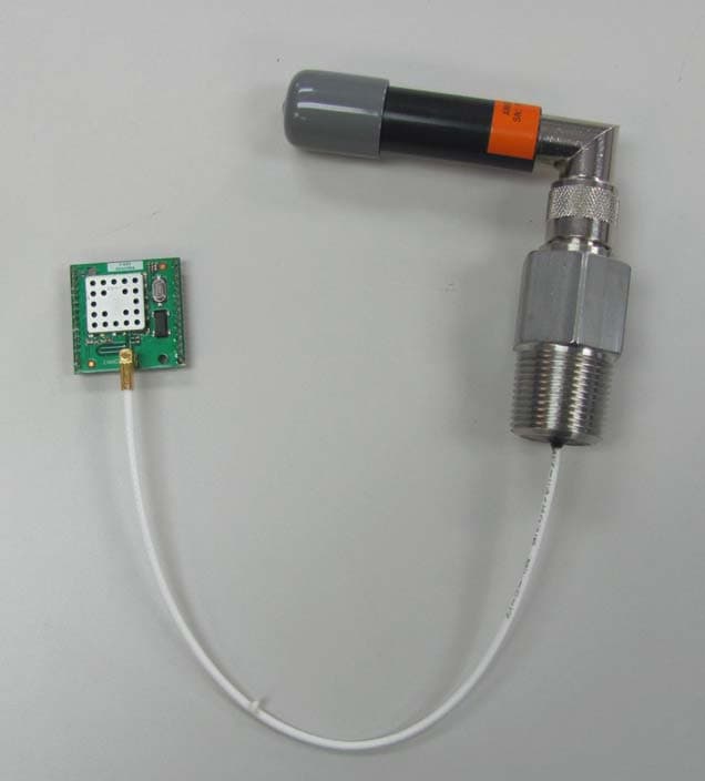
Z7KMRKW0515
Jan 04, 2016Wireless HART Transmitter
Equipment Class
DTS - Digital Transmission System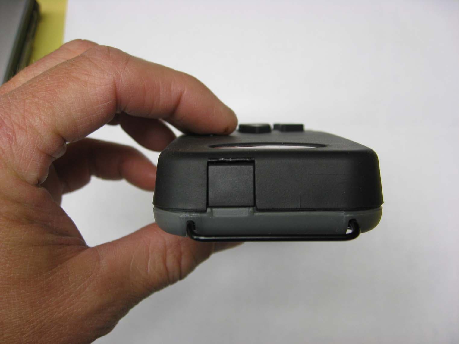
Z7KUHH0032011
Nov 07, 2011Base Universal Handheld Module
Equipment Class
DTS - Digital Transmission System