Z8GTX4060Professional Wireless Pool Thermometer
Tiankan Electronic Technology CO.,LTD.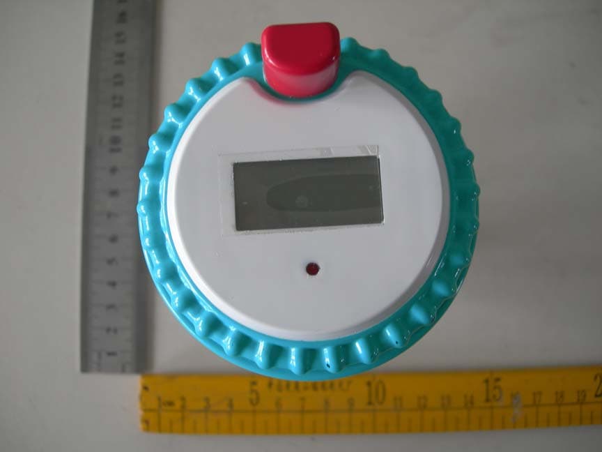
Click to zoom
Application Details
- Equipment Class
- DSC - Part 15 Security/Remote Control Transmitter
- Date of Grant
- Dec 11, 2011
- Application Purpose
- Original Equipment
- Date of Application
- Dec 11, 2011
- Equipment Note
- Professional Wireless Pool Thermometer
- Frequency Range
- 433.95000000 - 433.95000000
- Country
- China
Documents & Files
Document Text
Text extracted from the exhibit documents filed with the FCC. Open a document above to read the original.
Users Manual
Professional Wireless Pool Thermometer Manual Receiver WT0122 z Specifications: 1、Calendar from Jan. 1 st , 2000 to Dec.31 st ,2099 2、Alarm with snooze; 3、Water temperature range:-40 to +70°C°C; 4、Indoor temperature range:-50 to +70°C°C; 5、433MHZ wireless receives 3 channel's water temperature; 6、Max/min record of indoor and water temperature. z Keys: Totally has 6 keys: 1﹑[MAX/MIN]: (1)In normal clock mode, press [MAX/MIN] to toggle the display of maximum ,minimum and current data of indoor temperature and water temperature. (2)In hour setting mode, press [MAX/MIN] to toggle 12/24 hour format. 2﹑[CHANNEL]:(1)In normal clock mode, press [CHANNEL] to toggle water temperature of channel 1/2/3. (2)While alarming, press [CHANNEL] to get into snooze. (3)In date mode, press [CHANNEL] to enter the RF test mode. 3﹑[CLEAR]:While displaying max/min indoor temperature and water temperature, press [CLEAR] to clear maximum/minimum data. 4﹑[MODE]:Press [MODE] to toggle modes 5﹑[SET]:Press [SET] to get into setting mode.(Such as year, month, date, hour, minute, second etc.) 6﹑[/]°C°F: (1)Press [/] to toggle temperature unit between or .°C°F °F °C (2) Press [/] to adjust the data.°C°F (3) In alarm non-setting mode, press [/] to turn on/off the°C°F bell. z Reset operation LCD displays fully for 2 seconds, then enter clock non-setting mode. At this time, it begins checking indoor temperature immediately, and entering RF testing state to receive 3 channels data. z Operation statement Press [MODE] to toggle between clock mode and alarm mode. 1﹑Clock Mode In normal clock mode, LCD displays indoor temperature, water temperature, month, date, week, hour, minute, second, and reception channel.As shown below: 1) Press [SET] to enter hour setting mode. While the number of hour is flashing, press [/°C°F] to adjust it. And press [ /] for more than 2 seconds to adjust in 8HZ.°C°F 2) Press [SET] to switch to minute setting mode. While the number of minute is flashing, press [/] to adjust it. And press [/] for more than 2 seconds to adjust in 8HZ.°C°F °C°F 3) Press [SET] to switch to second setting mode. While the number of second is flashing, press [/] to clear it. °C°F 4) In clock setting mode, press [MAX/MIN] to toggle between 12/24 hour format. 5) Press [SET] to confirm and quit clock setting mode, then back to normal clock mode. 6) In normal clock mode, press [MAX/MIN] to toggle the maximum, minimum and current data of indoor temperature and water temperature. When displaying maximum/minimum data of indoor and water temperature, press [CLEAR] to clear the data. 7) Press [CHANNEL] to toggle channel 1,channel 2 and channel 3. 8) Press [/] to toggle temperature unit between and .°C°F °F °C 9) If no button is pressed in 1 minute in clock setting mode, it will be back to clock mode automatically. 10) Press [MODE] to enter alarm mode. 2﹑Alarm Mode In normal clock mode, press [MODE] to enter alarm mode. LCD displays indoor temperature, water temperature, month, date, week, hour, minute, and reception channel.As shown below: 1) Press [SET] to enter hour setting mode. While the number of hour is flashing, press [/] to °C°F adjust it. And press [ /] for°C°F more than 2 seconds to adjust in 8HZ; 2) Press [SET] to enter munite setting mode. While the number of minute is flashing, press [/ ] °C°F to adjust it. And press [/] for more than 2 seconds to adjust in 8HZ°C°F; 3) Press [SET] to confirm and quit. 4) In alarm non-setting mode, press [/] to open/close alarm.°C°F 5) If no button is pressed in 1 minute in alarm setting mode, it will be back to clock mode automatically. 6) Press[MODE] to enter date mode. 3﹑Date Mode In normal clock mode, press [MODE] 2 times to enter date mode. LCD displays indoor temperature, water temperature, month, date, week. As shown below: 1) Press [SET] to enter year setting mode. While the number of year is flashing, press [ /] to °C°F adjust it. And press [ /] for more than 2 seconds to adjust in 8HZ.°C°F 2) Press [SET] to switch to month setting mode. While the number of month is flashing, press [/] to adjust it. And press [/] for more than 2 seconds to adjust in 8HZ.°C°F °C°F 3) Press [SET] to switch to date setting mode. While the number of date is flashing, press [ / ] °C°F to adjust it. And press [/] for more than 2 seconds to adjust in 8HZ. °C°F 4) Press [SET] to confirm and quit. 5) If no button is pressed in 1 minute in date setting mode, it will be back to clock mode automatically. 6) In date mode, press [CHANNEL] to enter the RF test condition, and it will quit this mode automatically 10 minutes later. 4﹑Alarm with Snooze 1)When alarm is open, and it reaches the alarm time,it will buzzer“BI“ for one minute with the alarm icon flashing. 2)While alarming, press [CHANNEL] or no key pressed to stop alarming. At this time, "ZZ" icon flashing, it will enter snooze. Five minutes later, it will alarm. After the 5th alarming, it will no longer enter snooze. 3)While alarming, press any key to stop alarming, but not enter Snooze; 4)While snoozing, quit snoozing if enter setting mode. 5)In any mode, when reaches alarming time, press any key to close the alarm. z Power Consumption: 1、Alkaline battery:2×AAA 1.5V 2、Battery life:about 12 months z Dimension(H×W×D) 119mm×74mm×21mm. Transmitter TX4060 z Temperature Range:-40 to +°C60°C z Operating instructions: After the batteries are inserted it starts to sense water temperature and transmit temperature data to main station. Red LED flashes while transmission is proceeding. z Channel and unit option instructions: 1 2 CHANNEL DOWN DOWN CH1 UP DOWN CH2 DOWN UP CH3 Pull down both the switch 1 and 2 to enter Channel 1. Push up the switch 1, and pull down the switch 2 to enter Channel 2. Pull down the switch 1 and push up the switch 2 to enter Channel 3. DOWN UP 3 °F °C Pull down the switch 3 to choose °F. Push up the switch 3 to choose °C. z Power consumption 1、Alkaline battery:2×AA 1.5V 2、Battery life:about 12 months z Battery Installation Instruction 1. Tw…
Text truncated - open the document above for the full version.
Cover Letter(s)
SCS-F18: Project and Product Certification Representative Authorization Letter Page 1 of 2 Rev 2.0 2206 Ringwood Avenue San Jose, CA 95131 Tel: 408-526-1188 Fax: 408-526-1088 Email: [email protected] Project and Product Certification Representative Authorization Letter Revision History Reason for Amendment (current / obsolete) From To Approved Date Initial Release (current) 1.0 1.0 Nov-14-2006 Revised wording (current) 1.0 2.0 Sept–25-2007 SCS-F18: Project and Product Certification Representative Authorization Letter Page 2 of 2 Rev 2.0 TIANKAN ELECTRONIC TECHNOLOGY CO., LTD. Date: November 09, 2011 To: SIEMIC, INC. 2206 Ringwood Avenue, San Jose, CA 95131 USA Dear Sir/Madam, Re: Project and Product Certification Representative Authorization Letter We, Tiankan Electronic Technology CO., LTD. hereby authorize SIEMIC, INC. to act as a Certification Body for certifying for the following project(s): Professional Wireless Pool Thermometer TX4060 We affirm that between SIEMIC and Tiankan Electronic Technology CO., LTD, any difference in understanding, including test plan, measurement methods, applicable standards and relevant procedures and processes have been resolved prior to commencement of testing activities. Sincerely, Client’s signature Client’s name / title : Xie Kailong / Manager Contact information / address Building B11, Shasan Ditang Road, Shajing, Baoan District, Shenzhen, Guangdong Province, P.R.China.
Cover Letter(s)
SCS-F19: Confidentiality Request Letter Page 1 of 2 Rev 2.0 2206 Ringwood Avenue San Jose, CA 95131 Tel: 408-526-1188 Fax: 408-526-1088 Email: [email protected] Confidentiality Request Letter Revision History Reason for Amendment (current / obsolete) From To Approved Date Initial Release (current) 1.0 1.0 Nov-14-2006 Adding CFR 2.459 1.0 2.0 August – 11 - 2008 SCS-F19: Confidentiality Request Letter Page 2 of 2 Rev 2.0 TIANKAN ELECTRONIC TECHNOLOGY CO., LTD. Date: November 09, 2011 To: Federal Communications Commission Authorization and Evaluation Division 7435 Oakland Mills Road Columbia, MD Confidentiality Request regarding application for certification of FCC ID: Z8GTX4060 We hereby request confidential treatment of information accompanying this application as outlined below: - Schematic - manual - block diagram The above materials contain trade secrets and proprietary information not customarily released to the public. The public disclosure of these materials may be harmful to the applicant and provide unjustified benefits to its competitors. The applicant understands that pursuant to Section 0.457 & 0.459 of the Rules, disclosure of this application and all accompanying documentation will not be made before the date of the Grant for this application. Sincerely, Client’s signature Client’s name / title : Xie Kailong / Manager Contact information / address: Building B11, Shasan Ditang Road, Shajing, Baoan District, Shenzhen, Guangdong Province, P.R.China.
External Photos
EXTERNAL PHOTO
ID Label/Location Info
FCC Certification Label Sample FCC Certification Label Location Sample Label Location
Internal Photos
INTERNAL PHOTO ANTENNA
Test Report
FCC CERTIFICATION REPORT For PROFESSIONAL WIRELESS POOL THERMOMETER Trade Name : N/A Model Number: TX4060 FCC ID : Z8GTX4060 Report Number : SZ1110020-FC Date : November 21, 2011 Prepared for: TIANKAN ELECTRONIC TECHNOLOGY CO., LTD BUILDING B11, SHASAN DITANG ROAD, SHAJING, BAOAN DISTRICT, SHENZHEN, GUANGDONG PROVINCE, P.R.CHINA. Prepared by: SEC ENGINEERING SERVICES CO., LTD. 21A BLDG. C, SHENNAN GARDEN, SCIENCE & TECHNOLOGY PARK, NANSHAN, SHENZHEN, GUANGDONG, P.R.CHINA TEL: 86-755-86110163 FAX: 86-755-86110248 Report Number: SZ1110020-FC November 21, 2011 SEC Engineering Service Co., Ltd. Page 2 of 20 TABLE OF CONTENTS 1 CERTIFICATION OF COMPLIANCE .........................................................................................................................................4 2 TEST SUMMARY ..............................................................................................................................................................................5 3 GENERAL INFORMATION............................................................................................................................................................6 3.1 SYSTEM DESCRIPTION ..........................................................................................................................................................6 3.2 PRODUCT INFORMATION......................................................................................................................................................6 3.3 SUPPORT EQUIPMENT............................................................................................................................................................6 4 TEST FACILITY.................................................................................................................................................................................7 5 TEST EQUIPMENT LIST ................................................................................................................................................................8 6 THE FIELD STRENGTH OF RADIATION EMISSION...........................................................................................................9 6.1 BLOCK DIAGRAM OF TEST SETUP................................................................................................................................................9 6.2 THE FIELD STRENGTH OF RADIATION EMISSION MEASUREMENT LIMITS..................................................................................9 6.3 CONFIGURATION OF EUT ON MEASUREMENT.............................................................................................................................9 6.4 OPERATION CONDITION OF EUT ............................................................................................................................................... 10 6.5 TEST PROCEDURE....................................................................................................................................................................... 10 6.6 THE FIELD STRENGTH OF RADIATION EMISSION MEASUREMENT RESULTS............................................................................ 10 7 20DB OCCUPIED BANDWIDTH.................................................................................................................................................11 7.1 BLOCK DIAGRAM OF TEST SETUP..............................................................................................................................................11 7.2 THE BANDWIDTH EMISSION MEASUREMENT LIMIT..................................................................................................................11 7.3 CONFIGURATION OF EUT ON MEASUREMENT...........................................................................................................................11 7.4 OPERATION CONDITION OF EUT ................................................................................................................................................11 7.5 TEST PROCEDURE....................................................................................................................................................................... 12 7.6 THE BANDWIDTH EMISSION MEASUREMENT RESULT............................................................................................................. 12 8 DURATION TIME AND SILENT PERIOD MEASUREMENT ........................................................................................... 13 8.1 BLOCK DIAGRAM OF TEST SETUP............................................................................................................................................. 13 8.2 THE DURATION TIME AND SILENT PERIOD MEASUREMENT LIMIT.......................................................................................... 13 8.3 CONFIGURATION OF EUT ON MEASUREMENT.......................................................................................................................... 13 8.4 OPERATION CONDITION OF EUT ............................................................................................................................................... 13 8.5 TEST PROCEDURE....................................................................................................................................................................... 14 8.6 THE MEASUREMENT RESULT..................................................................................................................................................... 14 9 AVERAGE FACTOR MEASUREMENT ................................................................................................................................... 15 9.1 BLOCK DIAGRAM OF TEST SETUP............................................................................................................................................. 15 9.2 THE AVERAGE FACTOR MEASUREMENT................…
Text truncated - open the document above for the full version.
Test Setup Photos
PHOTOGRAPHS Photographs –Test Setup The Field Strength of Radiation Emission (Below 1GHz) The Field Strength of Radiation Emission (Above 1GHz)
Contact Information
Applicant
Helen Chen
Test Firm
SGS-CSTC Standards Technical Services Co.,Ltd.June Zhang
Technical Specifications
| # | Rule Parts | Frequency Range | Power Output |
|---|---|---|---|
| 1 | 15.231(e) | 433.95 MHz - 433.95 MHz | - |