Z9B-SIGNVisual Indicator
Dive In Ventures, LLC dba HeadsUp Systems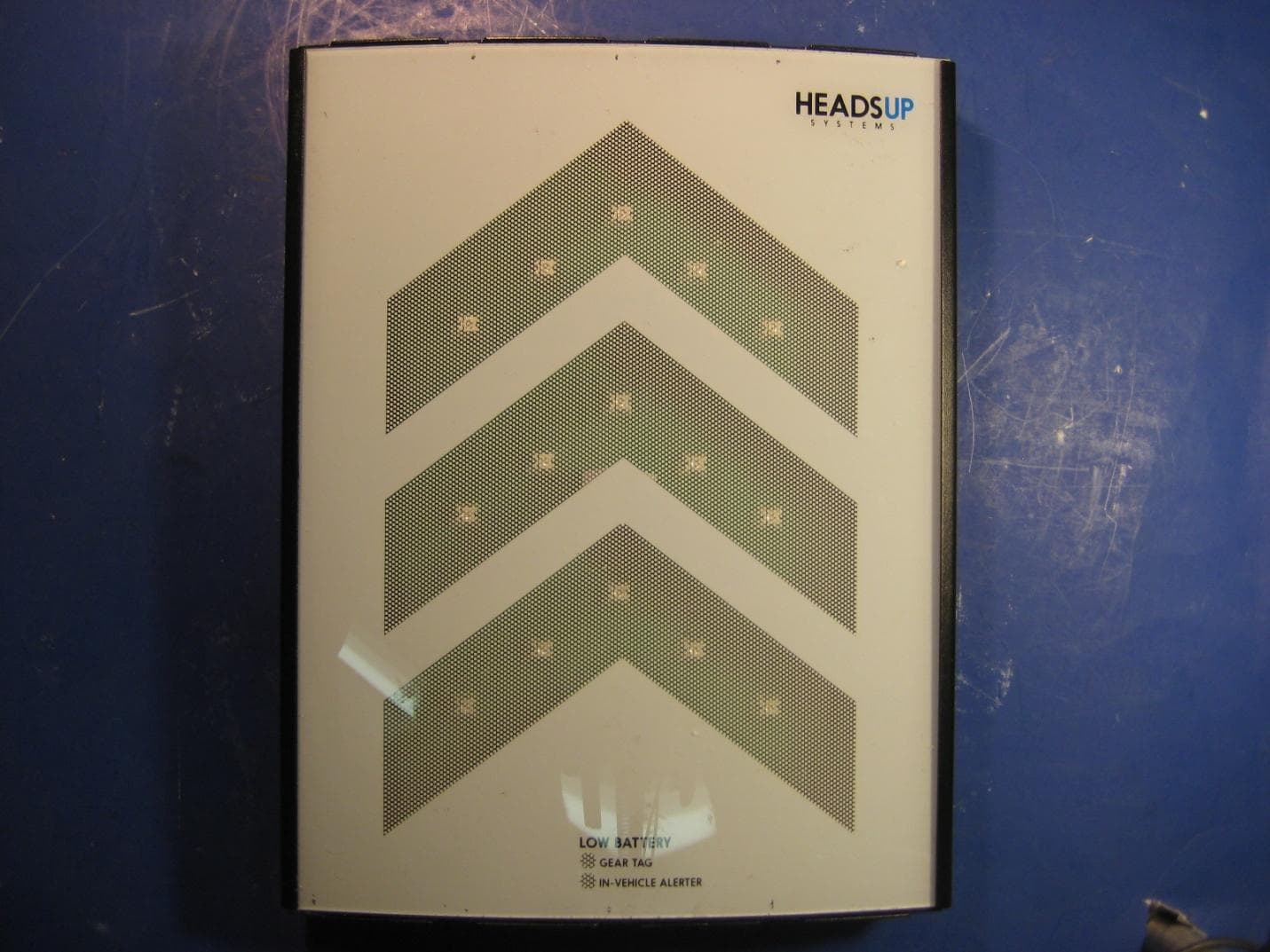
Click to zoom
Application Details
- Equipment Class
- DXT - Part 15 Low Power Transceiver, Rx Verified
- Date of Grant
- Mar 25, 2012
- Application Purpose
- Original Equipment
- Date of Application
- Mar 20, 2012
- Equipment Note
- Visual Indicator
- Frequency Range
- 2424.00000000 - 2424.00000000
- Country
- United States
Documents & Files
Document Text
Text extracted from the exhibit documents filed with the FCC. Open a document above to read the original.
Users Manual
User & Setup Guide V1.3 2 TABLE OF CONTENTS 1.Box Contents 2.Setup 3.How It Works 4.Warranty & Legal 5.Product Registration & Feedback 3 1. BOX CONTENTS •User & Setup Guide •8.5" x 11" LED Alert Sign with Internal Wireless Control Module •Two (2) Water-resistant Gear Tags, including batteries •One (1) InCar Alerter, including battery •110V AC/12V DC Transformer •Mounting Screws/Mollies (for Sign) •HeadsUp Stickers 4 2. SETUP A.Put battery in each Gear Tag. 1. Gently stretch silicon cover!2. Insert battery with to remove plastic case.!the + side up. 3. Put plastic case back!4. Done. into silicone cover. 5 B.Put battery in InCar Alerter. 1. Slide open battery!2. Insert battery with cover.!the + side up. 3. Replace battery cover.!4. Done. Option: slide on visor clip. Note: When you eventually have to replace the battery, use a small screwdriver or letter opener to push the battery out of the battery holder from the far side of the opening: 6 C.Mount Alert Sign. approx. 4 feet high 1. Mount Alert Sign to inside garage wall wherever it will be most visible to the driver when approaching the garage. Screws are provided, and there are keyhole slots on the back of the sign to help hang the sign. This is most likely the back wall of the garage if you approach your garage head on, or the side wall if you approach your garage from the side - just put it where you normally look as you are pulling into the garage. 2. With the InCar Alerter in the garage with you, plug the Alert Sign into a wall outlet using the enclosed power adapter. Use an extension cord for the power adapter if your outlet is further away than the cord on the adapter. 3. As soon as the Alert Sign is plugged in, it will flash for several seconds to show you it is working. It will also send a signal to trigger your InCar Alerter so you can hear what it sounds like. You can silence the Alerter by pressing the button on it; otherwise it will stop beeping automatically in three minutes. 7 D.Place Gear Tags on Gear. There are many options for mounting your gear tag. You can use the strap to attach it to any tube on your bicycle. Or if you have a saddle bag or cargo bag that always stays on your bike, just place it inside. Just make sure it is something that is always with your bike. For kayaks, canoes or cargo carriers, you can use the silicon strap to attach a Gear Tag to a bar on the inside of your equipment, or simply place it in your watercraft storage bin. E.Place Alerter in Vehicle. Put the Alerter device in your car wherever you will hear it when it goes off. For the best range, we recommend clipping it to your sun visor or rearview mirror post. F.Done! We recommend that you test your system to make sure everything is installed correctly and working before you rely on it. The alert range will vary slightly based on your garage, vehicle and placement of the components, so make sure you drive several blocks away for a couple minutes and then return to test the system and confirm the alert range for your set-up. (Important Note: Wait 3 minutes after plugging in your sign to do your test and at least 3 minutes between any subsequent tests for the system to fully reset each time.) 8 3. HOW IT WORKS Once your HeadsUp System is installed, it protects you and your gear every time you return home with gear on your roof rack. The Alert Sign is always on, listening for Gear Tags and InCar Alerters. When you return home with your gear on the roof and come within range of the Sign, the Sign detects a new Gear Tag and Alerter and triggers the alert sequence. The Sign begins flashing for 3 minutes, providing you with a visual alert, and the InCar Alerter starts beeping to alert you inside your vehicle. You can silence the Alerter at any time by pressing its button if you want to stop the beeping before it stops automatically in 3 minutes. The visual and audio alerts remind you to unload your roof-mounted gear before you drive in to the garage. And it works every time, saving you from potentially thousands of dollars of damage to your gear, rack, vehicle and garage. Smart move! Additional Notes •The Alerter should stay in your vehicle at all times. Driving in and out of your garage without your gear with just the Alerter in your vehicle will not trigger an alert. •You can ride your bicycle with its Gear Tag directly from your garage and the sign will not go off when you return. The alerts only go off when both a Gear Tag and a vehicle with an Alerter return at the same time. 9 •If you store your bicycles, kayaks or other gear with Gear Tags in your garage, the Sign detects that they are present and ignores them for deciding when an alert is needed. A Gear Tag and Alerter need to both be away from your Alert Sign for more than 30 seconds to trigger an alert when you return home. •Your Gear Tags should always be with the gear you want to protect. A Tags can easily be mounted on your bike by wrapping the silicon strap around any tube on your bike as shown in the Installation instructions above. If you have a saddle bag that always stays on your bike, you can just tuck a Gear Tag in that instead. For kayaks, canoes or cargo carriers, you can either use the silicon strap to attach a Gear Tag to the inside of your gear, or simply place it in your watercraft storage bin. The silicon housing on the Gear Tag is water-resistant, but if your tag is likely to sit in water for extended periods, we suggest placing it in a zip-seal bag first. •If, for some reason, you are carrying your gear with a Gear Tag in your trunk instead of on the roof rack, the alert will still go off (although the alert range may be reduced). The Alert Sign senses when you return home in your vehicle with your gear, whether or not the gear is on the roof. •More than one vehicle with a roof rack? No problem: extra InCar Alerters are available individually at headsupsystems.com and at many retailers that carry the HeadsUp System. •More than two bicycles or other gear you want to protect…
Text truncated - open the document above for the full version.
Cover Letter(s)
October 3, 2011 To Whom It May Concern: We the undersigned hereby delegate power of attorney to CKC Certification Services, LLC (CKC CS) to act on our behalf in matters of radio equipment certification. CKC CS is appointed as an agent to sign applications before regulatory agency(ies) on our behalf, and to receive and exchange data between our company and the agency(ies). Sincerely, President, Co-Founder HeadsUp Systems HeadsUp Systems | 283 Columbine St., #164 | Denver, CO 80206 | 888.521.6773 www.headsupsystems.com
Cover Letter(s)
Better Embedded Engineering LLC 3152 Boeing Road Cameron Park, CA 95682 USA “From Concept to Volume Production” FCC Confidential Authorization March 9 th , 2012 FEDERAL COMMUNICATIONS COMMISSIONS Authorization and Evaluation Division 7435 Oakland Mills Road Columbia, MD 21046 Subject: Confidentiality Request regarding application for certification of FCC ID: Z9B-SIGN In accordance with Sections 0.457 and 0.459 of the Commission’s Rules, SynapSense Corporation hereby requests long-‐term confidential treatment of information accompanying this application as outlined below: • Block Diagram • Schematics • Operation Description The above materials contain proprietary and confidential information not customarily released to the public. The public disclosure of these materials provides unjustified benefits to its competitors in the market. Sincerely, Pat Weston Owner
Cover Letter(s)
March 19, 2012 To Whom It May Concern: I hereby appoint Pat Weston of Better Embedded Engineering, LLC, as our agent to sign letters and applications for any filings with regulatory agencies on our behalf, and to receive and exchange data between our company, the agents company and the agency in connection with certification for any products that our company owns or manufactures. Sincerely, Karl Sowa President & Co-Founder HeadsUp Systems HeadsUp Systems | 283 Columbine St., #164 | Denver, CO 80206 | 888.521.6773 www.headsupsystems.com
Test Report
This report contains a total of 28 pages and may be reproduced in full only. Partial reproduction may only be done with the written consent of CKC Laboratories, Inc. Heads Up Systems TEST REPORT FOR Visual Indicator, EGAS Sign Tested To The Following Standards: FCC Part 15 Subpart C Sections 15.207, 15.249 and RSS 210 Issue 8 Report No.: 91979-10 Date of issue: December 20, 2011 This test report bears the accreditation symbol indicating that the testing performed herein meets the test and reporting requirements of ISO/IEC 17025 under the applicable scope of EMC testing for CKC Laboratories, Inc. We strive to create long-term, trust based relationships by providing sound, adaptive, customer first testing services. We embrace each of our customers’ unique EMC challenges, not as an interruption to set processes, but rather as the reason we are in business. Page 2 of 28 Report No.: 91979-10 TABLE OF CONTENTS Administrative Information ........................................................................................................................................... 3 Test Report Information ............................................................................................................................................ 3 Report Authorization ................................................................................................................................................. 3 Test Facility Information ............................................................................................................................................ 4 Site Registration & Accreditation Information .......................................................................................................... 4 Summary of Results ................................................................................................................................................... 5 Conditions During Testing.......................................................................................................................................... 5 Equipment Under Test ............................................................................................................................................... 6 Peripheral Devices ..................................................................................................................................................... 6 FCC Part 15 Subpart C .................................................................................................................................................... 7 15.207 AC Conducted Emissions ................................................................................................................................ 7 15.249 RF Power Output / Spurious Emissions ....................................................................................................... 14 -20dBc Occupied Bandwidth ................................................................................................................................... 20 Bandedge ................................................................................................................................................................. 22 RSS-210 ........................................................................................................................................................................ 25 99 % Bandwidth ....................................................................................................................................................... 25 Supplemental Information .......................................................................................................................................... 27 Measurement Uncertainty ...................................................................................................................................... 27 Emissions Test Details .............................................................................................................................................. 27 Page 3 of 28 Report No.: 91979-10 ADMINISTRATIVE INFORMATION Test Report Information REPORT PREPARED FOR: REPORT PREPARED BY: Heads Up Systems 850 Lafayette Street Denver, CO 80218 Dianne Dudley CKC Laboratories, Inc. 5046 Sierra Pines Drive Mariposa, CA 95338 Representative: Pat Weston Project Number: 91979 DATE OF EQUIPMENT RECEIPT: November 7, 2011 DATE(S) OF TESTING: November 7- December 6, 2011 Report Authorization The test data contained in this report documents the observed testing parameters pertaining to and are relevant for only the sample equipment tested in the agreed upon operational mode(s) and configuration(s) as identified herein. Compliance assessment remains the client’s responsibility. This report may not be used to claim product endorsement by A2LA or any government agencies. This test report has been authorized for release under quality control from CKC Laboratories, Inc. Steve Behm Director of Quality Assurance & Engineering Services CKC Laboratories, Inc. Page 4 of 28 Report No.: 91979-10 Test Facility Information Our laboratories are configured to effectively test a wide variety of product types. CKC utilizes first class test equipment, anechoic chambers, data acquisition and information services to create accurate, repeatable and affordable test results. TEST LOCATION(S): CKC Laboratories, Inc. 110 Olinda Place Brea, CA 92823 Site Registration & Accreditation Information Location CB # Japan Canada FCC Brea A US0060 R-2945, C-3248 & T-1572 3082D-1 90473 Page 5 of 28 Report No.: 91979-10 SUMMARY OF RESULTS Standard / Specification: FCC Part 15 Subpart C and RSS 210 Issue 8 Description Test Procedure/Method Results Conducted Emissions FCC Part 15 Subpart C Section 15.207 / ANSI C63.4 (2003) Pass RF Power Output / Spurious Emissions FCC Part 15 Subpart C Section 15.249 Pass -20dBc Occupied Bandwidth FCC Part 15 Subpart C Section 15.249 Pass Bandedge FCC Part …
Text truncated - open the document above for the full version.
Contact Information
Applicant
Karl Sowa(President, Co-Founder)
Technical Contact
Better Embedded EngineeringPat Weston
[email protected]5306767834
850 Lafayette Street · Denver, Colorado · United States
Non-Technical Contact
Dive In Ventures, LLCKarl Sowa
[email protected]3038680742
Test Firm
CKC Laboratories, Inc.Steve Behm
Technical Specifications
| # | Rule Parts | Frequency Range | Power Output |
|---|---|---|---|
| 1 | 15C | 2.42 GHz - 2.42 GHz | - |
Other Applications from Dive In Ventures, LLC dba HeadsUp Systems

Z9B-ALERTER
Mar 25, 2012In Vehicle Obstacle Alerter
Equipment Class
DXT - Part 15 Low Power Transceiver, Rx Verified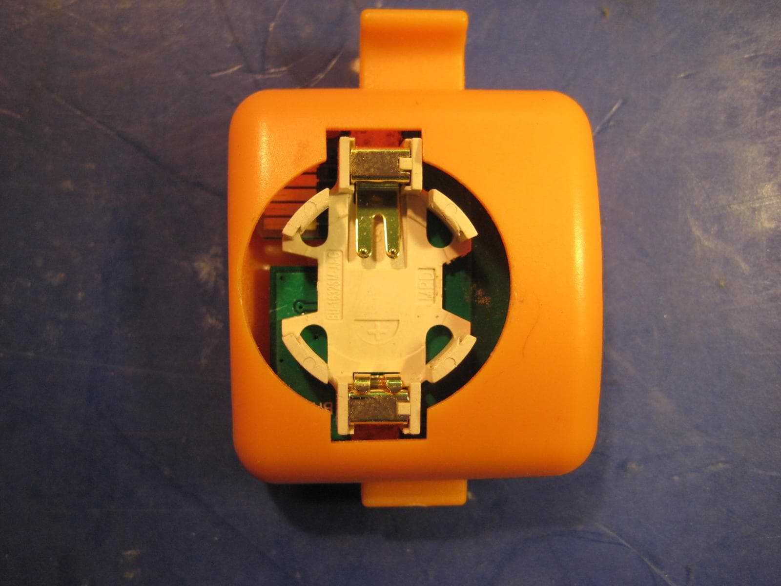
Z9B-BEACON
Mar 25, 2012EGAS Beacon
Equipment Class
DXT - Part 15 Low Power Transceiver, Rx Verified