ZAA-GT-900100Tracking device
Guardtrax LLC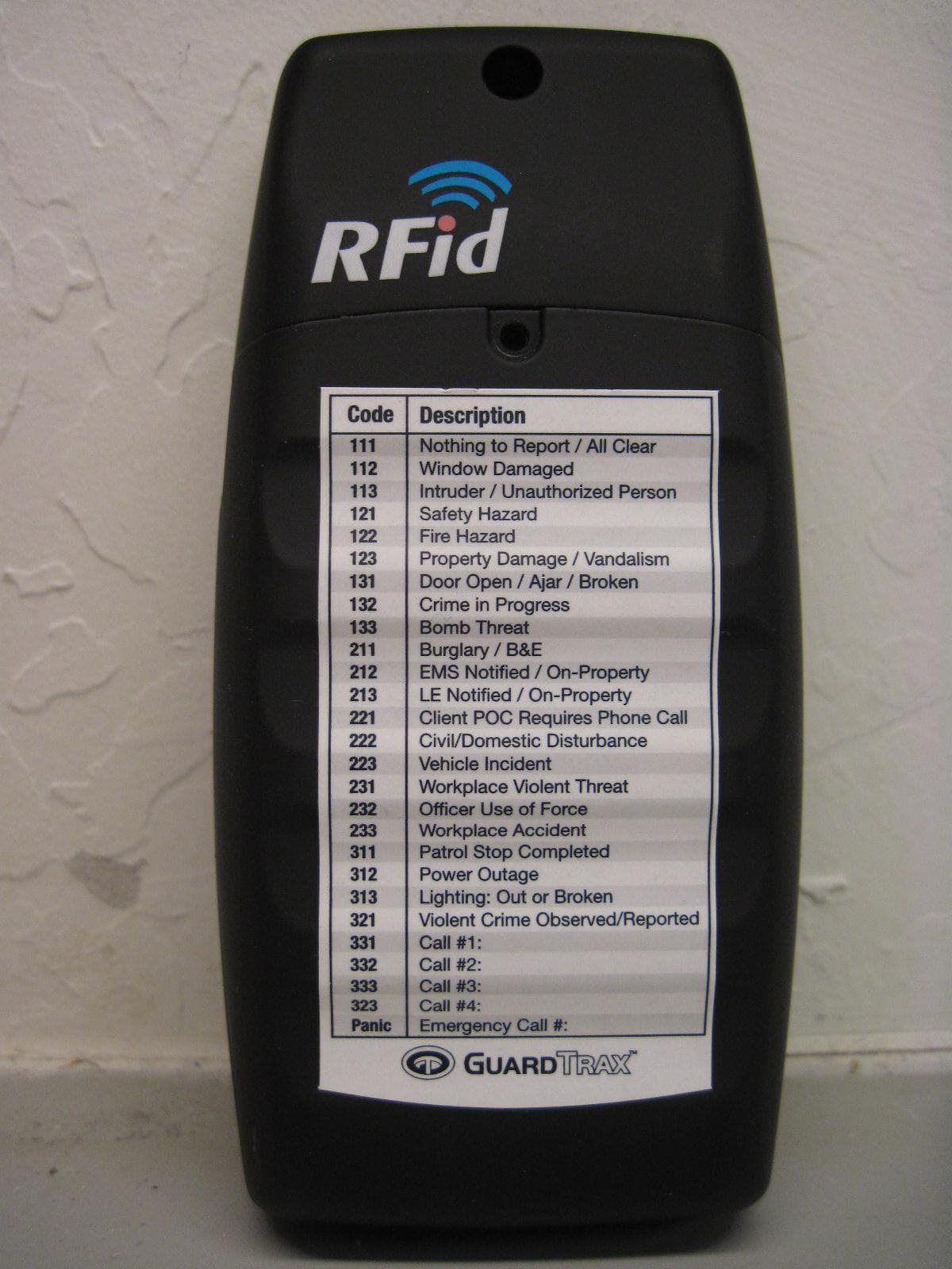
Click to zoom
Application Details
- Equipment Class
- PCB - PCS Licensed Transmitter
- Date of Grant
- Apr 20, 2011
- Application Purpose
- Original Equipment
- Date of Application
- Apr 20, 2011
- Equipment Note
- Tracking device
- Frequency Range
- 1850.50000000 - 1909.80000000
- Company
- Guardtrax LLC
- Country
- United States
Documents & Files
Document Text
Text extracted from the exhibit documents filed with the FCC. Open a document above to read the original.
Users Manual
The following paragraphs are to be added to the Users Guide: FCC Compliance statement (United States) FCC Class B part 15 This device is verified to comply with part 15 of the FCC Rules. Operation is subject to the following two conditions: (1) This device may not cause harmful interference, and (2) this device must accept any interference received, including interference that may cause undesired operation. Caution Changes or modifications not expressly approved by the party responsible for compliance could void the user’s authority to operate the equipment. This equipment has been tested and found to comply with the limits for a Class B digital device, pursuant to part 15 of the FCC Rules. These limits are designed to provide reasonable protection against harmful interference in a residential installation. This equipment generates, uses and can radiate radio frequency energy and, if not in-stalled and used in accordance with the instructions, may cause harmful interference to radio communications. However, there is no guarantee that interference will not occur in a particular installation. If this equipment does cause harmful interference to radio or television reception, which can be determined by turning the equipment off and on, the user is encouraged to try to correct the interference by one or more of the following measures: —Reorient or relocate the receiving antenna. —Increase the separation between the equipment and receiver. —Connect the equipment into an outlet on a circuit different from that to which the receiver is connected. _ Consult the dealer or an experienced radio or TGV technician for help. This equipment complies with the FCC RF radiation exposure limits set forth for an uncontrolled environment. This equipment complies with the Specific Absorption Rate (SAR) RF exposure requirements specified in ANSI/IEEE Std. C95.1-1992 and FCC 47 CFR 2.1093 for the General Population/ Uncontrolled Exposure environment when used with a holster for body worn configuration. This transmitter must not be co-located or operating in conjunction with any other antenna or transmitter. Industry Canada Certification The Guardtrax 2.0 Model GT-900100 complies with industry Canada RSS -132 and RSS – 133 under certification number 9528A. Under Industry Canada regulations, this radio transmitter may only operate using an antenna of a type and maximum (or lesser) gain approved for the transmitter by Industry Canada. To reduce potential radio interference to other users, the antenna type and its gain should be so chosen that the equivalent isotropically radiated power (e.i.r.p.) is not more than that necessary for successful communication. Conformément à la réglementation d'Industrie Canada, le présent émetteur radio peut fonctionner avec une antenne d'un type et d'un gain maximal (ou inférieur) approuvé pour l'émetteur par Industrie Canada. Dans le but de réduire les risques de brouillage radioélectrique à l'intention des autres utilisateurs, il faut choisir le type d'antenne et son gain de sorte que la puissance isotrope rayonnée équivalente (p.i.r.e.) ne dépasse pas l'intensité nécessaire à l'établissement d'une communication satisfaisante. This device complies with Industry Canada licence-exempt RSS standard(s). Operation is subject to the following two conditions: (1) this device may not cause interference, and (2) this device must accept any interference, including interference that may cause undesired operation of the device. Le présent appareil est conforme aux CNR d'Industrie Canada applicables aux appareils radio exempts de licence. L'exploitation est autorisée aux deux conditions suivantes : (1) l'appareil ne doit pas produire de brouillage, et (2) l'utilisateur de l'appareil doit accepter tout brouillage radioélectrique subi, même si le brouillage est susceptible d'en compromettre le fonctionnement. Privacy of communications may not be ensured when using this telephone. Les communications effectuées au moyen de cet appareil ne sont pas nécessairement protégées des indiscrétions.
Users Manual
Quick Start Guide Thank you for ordering the GT2 Security Force Locator. Contained in this box you will find the following items: IMPORTANT NOTE: Prior to powering up the device, it is very important that the GT2 be charged for six (6) hours upon its first charge. Insert the mini USB connector of the included USB cable into the USB connector on the side of the GT2. Connect the other end of the USB cable to the included wall/car charging adapter. Plug the wall/car charging adapter into a wall power outlet and your GT2 is now charging. Once you have charged your GT2 contact the Activation Hotline at 443-766-1337 between 10am and 3pm EST Monday – Friday to activate your device and receive your account username and password. GT2 Security Force Locator Device USB charging cord with plug-in adapter GT2 carrying holster RFID Tags (As per your order) 2 Now that your GT2 is charged and activated, you may power the device ON by pressing and holding the ENTER button for five (5) seconds, or until the LCD displays “PWR ON”. You can expect to see the word “READY” appear on the LCD display upon powering up the device. GSM: Within the first minute, you can expect to see the GSM service level bars appear in the upper right corner of the LCD display. These bars indicate the GSM signal strength and connec- tion to the GSM mobile network. Presence of the bars means your GT2 has the ability to transmit data. GPS: If you are within satellite coverage when you power your GT2 on, you will notice within 5-7 minutes, the appearance of a satellite icon in the upper left corner of the LCD display. The appearance of this icon indicates that the GT2 has an acceptable connection with the GPS satellites. (The 5-7 minute duration is due to initial- ization, power up and map almanac downloads.) NOTE: If you are indoors, when your GT2 is powered on, in most cases, the satellite icon will NOT appear in the left corner of the LCD display. Expect to acquire GPS connection within minutes of when your device has an unobstructed view of the sky. After powering on my GT2, what should I expect to see? 1 2 3 3 You will also see the battery level icon appear which is located in the lower left corner of the LCD display. The battery display has four (4) measurement bars indicating the strength of the battery level. The battery will typically power the device for 18 to 24 hours. It typically takes four (4) hours to recharge the GT2 completely. Finally , the date and time will appear in the lower right corner of the LCD display. The default setting is GMT but you may set your time zone with the menu option button. After powering on my GT2, what should I expect to see? (continued) 4 5 4 Your GT2 is now ready for action. Wherever you walk or drive, the GT2 will be reporting your activity to the GuardTrax web site located at www.myguardtrax.com. The LCD display has eight (8) icons plus an area to show messaging or feedback. See examples below. 5 How do I read an RFID tag with the GT2? With the GT2 powered on, and the word “READY” listed on the LCD display, you are now prepared to begin read- ing RFID tags. Press and hold the “ENTER/RFID” button on the front of the GT2 until the display reads “RFID ON” and the ‘RFID’ icon appears in the display (p. 5). By holding the enter button down, you are turning on the RFID reader. Once you see the RFID icon, you may release the enter button, as the RFID will remain active for five (5) minutes. Holding the device up-right to any tag thereafter will result in a positive scan. The RFID tag is read by holding the RFID marking on the back of the device up against the tag. {Vibrate and/or Beep} The GT2 has now read the RFID tag. After reading the RFID tag, the LCD will show “RFID OK”, indicating a positive read, and the GT2 immediately uploads the tag information to the GuardTrax web site (assuming you have GSM connection). To conserve battery, you may hold down the “Enter/RFID” button to turn off the RFID function. The RFID icon will disappear from the display. NOTE: The GT2 RFID reader will remain on for five (5) minutes or until another RFID tag is read, which will then reset the five (5) minute timer. If another tag is not read within the five (5) minute window, the RFID reader must be turned on again by following the steps listed above. 1 2 3 4 6 How do I enter an incident code using the GT2? With the GT2 powered on and the word “READY” listed on the LCD display, you are now prepared to begin enter- ing incident codes. Enter the desired code by pressing the numbers on the keypad. (Example: 123) After entering the desired code, press the “ENTER” button on the keypad. The LCD display will then read “SENT” The GT2 has now sent the code together with your current GPS location point to the GuardTrax web site, where it will be displayed on the map as a keyed event. NOTE: In order for incident codes to be viewed on the map, you must have a valid GPS connection shown by the satellite in the top left corner of the LCD display. If there is no valid GPS, the web site, maps and alerts will mark the location as the last known valid GPS location. 1 2 3 4 7 111Nothing to Report/All Clear 112Window Damaged or Broken 113Intruder/Unauthorized Person 121Safety Hazard 122Fire Hazard 123Property Damage/Vandalism 131Door Found Open/Ajar/Broken 132Crime in Progress 133Bomb Threat 211Burglary/B&E 212EMS Notified/On-Property 213LE Notified/On-Property 221Client POC Requires Phone Call 222Civil/Domestic Disturbance 223Vehicle Incident 231Workplace Violence Threat 232Officer Use of Force 233Workplace Accident 311Patrol Stop Completed 312Power Outage 313Lighting: Burned Out/Broken 321Violent Crime Observed/Reported Key Code / Key Code Definition 8 How do I make a phone call using the GT2? The GT2 can be used as a limited mobile phone with its own dedicated phone number. When you ordered the GT2, we asked you to provide five (5) phone numbers that were programmed into the GT2. In order to call these numbers, a code is entered a…
Text truncated - open the document above for the full version.
Block Diagram
Guardtrax LLC 11 Commerce Drive Lobby floor Cranford New Jersey 07016 INTERGIS LLC: GUARD TRAX 2 GT-900100 - FCC ID: ZAA-GT-900100 OPERATIONAL / TECHNICAL DESCRIPTION The GT-900100 Guard Trax 2 is designed for use as a personal tracking and communication device.. This design incorporates an Atmel ATMega128 8-bit microcontroller, a Telit combination Quad Band GSM Modem/ 20 channel GPS Receiver, 3V 8 position SIM card interface, a DS1371 Real Time Clock, TI TRF7960/1 RFID AFE subsystem, a 512Kx8 SPI FLASH, a LP3470 POR, temperature sensor, light sensor, motion sensors, 10 position keypad interface, microphone and speaker audio subsystem, power supply and battery charging subsystem, a custom LCD interface with electroluminescent backlighting driver, USB subsystem, and the specified interface/debug connectors. BLOCK DAIGRAM Figure 1 - Functional Block Diagram
Cover Letter(s)
Guardtrax LLC 11 Commerce Drive Lobby floor Cranford New Jersey 07016 MET Laboratories, Inc. 914 West Patapsco Aveenue Baltimore, MD 21230 RE: FCC Labeling requirements To whom it may concern: In accordance with FCC part 15, section 15.19 Labeling requirements, Paragraph 5) When the device is so small or for such use that it is not practicable to place the statement specified under paragraph (a) of this section on it, the information required by this paragraph shall be placed in a prominent location in the instruction manual or pamphlet supplied to the user or, alternatively, shall be placed on the container in which the device is marketed. However, the FCC identifier or the unique identifier, as appropriate, must be displayed on the device. To satisfy this requirement Guardtrax will add the following statement to the GT-900100 user guide: This device complies with part 15 of the FCC Rules. Operation is subject to the following two conditions: (1) This device may not cause harmful interference, and (2) this device must accept any interference received, including interference that may cause undesired operation. Please contact me if there is any information you may need Sincerely, John Koch Product Engineer Guardtrax LLC Office: 908 458 4112 Mobile: 973 713 3212 email: [email protected]
Cover Letter(s)
Guardtrax LLC 11 Commerce Drive Lobby floor Cranford New Jersey 07016 MET Laboratories, Inc. 914 West Patapsco Aveenue Baltimore, MD 21230 RE: FCC Labeling requirements To whom it may concern: In accordance with FCC part 15, section 15.19 Labeling requirements, the FCC ID label may not be placed inside the battery compartment unless authorized by the FCC. In the current Guardtrax 2 design there is no area on the device that can accommodate this label. There is room under the battery cover, but the battery cover can easily be removed from the body of the device. Please arrange to request permission from the FCC to locate the label under the battery. Please contact me if there is any information you may need Sincerely, John Koch Product Engineer Guardtrax LLC Office: 908 458 4112 Mobile: 973 713 3212 email: [email protected]
External Photos
Photograph 1. Battery Back Photograph 2. Battery Front Photograph 3. Battery Side Photograph 4. EUT Front View Photograph 5. EUT Left Side Photograph 6. EUT Rear View Photograph 7. EUT Right Side Photograph 8. EUT with Battery Removed Photograph 9. EUT without Batter Cover
ID Label/Location Info
Model: GT-900100 Guardtrax LLC FCC ID ZAA-GT-900100 IC: 9528A-GT9001003582810007096039 REV 2.4 1.0 0.75 FCC VENDER LABEL Product OL28CL – ON LINE LABELS Clear Gloss Laser - 0.75" x 1"GT-700055 REV B BARCDE AREA BARCDE AREA BARCDE AREA
Internal Photos
Photograph 1. EUT Board Front View Photograph 2. EUT Board Read View Photograph 3. RFID Antenna
Operational Description
Guardtrax LLC 11 Commerce Drive Lobby floor Cranford New Jersey 07016 INTERGIS LLC: GUARD TRAX 2 GT-900100 - FCC ID: ZAA-GT-900100 OPERATIONAL / TECHNICAL DESCRIPTION The GT-900100 Guard Trax 2 is designed for use as a personal tracking and communication device.. This design incorporates an Atmel ATMega128 8-bit microcontroller, a Telit combination Quad Band GSM Modem/ 20 channel GPS Receiver, 3V 8 position SIM card interface, a DS1371 Real Time Clock, TI TRF7960/1 RFID AFE subsystem, a 512Kx8 SPI FLASH, a LP3470 POR, temperature sensor, light sensor, motion sensors, 10 position keypad interface, microphone and speaker audio subsystem, power supply and battery charging subsystem, a custom LCD interface with electroluminescent backlighting driver, USB subsystem, and the specified interface/debug connectors. BLOCK DAIGRAM Figure 1 - Functional Block Diagram
Parts List/Tune Up Info
Item # ASSEMBLY QTY REF DES DESCRIPTION MANUFACTURER MANUFACTURER PART # NT Part Number cost each extended price 200 HOUSING ASSY 1 TOP ENCLOSURE REV 2 PGI GT-700050-2 GT-700050 $ 3.52 3.5200 $ 201 HOUSING ASSY 1 BOTTOM ENCLOSURE REV 2 PGI GT-700051-2 GT-700051 $ 2.28 2.2800 $ 202 HOUSING ASSY 1 BATTERY COVER PGI GT-700052 GT-700052 $ 1.58 1.5800 $ 203 HOUSING ASSY 1 MEMBRANE KEYPAD PGI GT-800103 GT-800103 $ 4.88 4.8800 $ 237 HOUSING ASSY 1 GPS ANTENNA SLEEVE Sarantel BM1100S NT-260017 204 HOUSING ASSY 1 SPEAKER FILLTER GORE GAW1020613 NT-290002 $ 1.55 1.5500 $ 205 HOUSING ASSY 1 MICROPHONE FILTER Stockwell GT-700064 GT-700064 $ 0.15 0.1500 $ 206 HOUSING ASSY 5 SCREW, 2.5 mm X 6 mm Black Oxide Small Parts BCAS-M25456 NT-250016 $ 0.07 0.3500 $ SUB HOUSING ASSY 0 SCREW, 2.5 mm X 6 mm Black Oxide McMaster Car r 91239A755 NT-250016 219 HOUSING ASSY 1 BATTERY SUPPORT TAPE Stockwell GT-700063 GT-700063 $ 0.15 0.1500 $ 234 HOUSING ASSY 1 SUPPORT BAR , LCD DISPLAY - TOP 0.090" Stockwell GT-700067 GT-700067 $ 0.30 0.3000 $ 231 HOUSING ASSY 1 SUPPORT BAR, LCD DISPLAY- BOTTOM 0.09" Stockwell GT-700068 GT-700060 $ 0.30 0.3000 $ 232 HOUSING ASSY 1 RFID SPACER Stockwell GT-700061 GT-700061 $ 0.30 0.3000 $ 233 HOUSING ASSY 1 DOUBLE SIDED TAPE 3M 3M # 4951 NT-270001 $ 0.05 0.0500 $ 208 HOUSING ASSY 1 SIM CARD KORE NT-SIM001 $ 15.42 15.4200 $ 0 209 PACKAGING 1 LABEL- VENDER - GT-700055 $ 0.05 0.0540 $ 210 PACKAGING 1 BOX- WHITE, 7 1/2 X 3 1/4 X 7 ULINE S-157 NT-210004 $ 0.48 0.4800 $ 217 PACKAGING 1 INSERT GEORGE SWATEK NT-210006 $ 1.67 1.6700 $ 211 PACKAGING 1 BATTERY LI-ION PO CELL , 2000MAH, 3.7 V SHENZHEN ENCEL TECH E634169-04X NT-951010 3.82 $ 3.8200 $ 212 PACKAGING 1 INSTALLATION GUIDE- GT2 GT-400007-2 $ 0.80 0.8000 $ 213 PACKAGING 1 USB UNIVERSAL BATTERY CHARGER Richfield Electronics TCC-22 NT-951013 $ 3.30 3.3000 $ 214 PACKAGING 1 USB A / MICRO USB X 1.5 M CABLE ASSEMBLY Richfield Electronics USB A NT-951014 $ 0.70 0.7000 $ 215 PACKAGING 1 LABEL, GUARD TRA X GT-700058 $ 0.20 0.2000 $ 239 PACKAGING 1 LABEL, IMPORTANT GT-700066 $ 0.05 0.0500 $ 216 PACKAGING 1 LABEL, CODE NUMBERS GT-700059 $ 0.05 0.0500 $ 221 PACKAGING 1 HEX KEY 1.5 mm X 1 3/4 " Long McMaster Car r 7289A11 NT-951017 $ 0.05 0.0500 $ 238 PACKAGING 1 NEOPRENE CASE BESSTEC BCB5LB130 NT-951015 $ 1.68 1.6800 $ 218 ACCESSORIES 0 RFID TAG - SQUARE TECH PRINT NT-951012 - $ 220 ACCESSORIES 0 RFID TAG - RO UND ON METAL SAG NT-951016 - $ 235 ACCESSORIES GT2 RUBBER BOOT PGI NT-951018 236 ACCESSORIES LARGE NEOPRENE CASE BESSTEC NT-951019(1K PRICING) MATERIAL $ 43.6840 300 PCS LABOR ASSEMBLY $ 11.2500 MAIN PCB ASSY REV 2.4 MAIN PCB ASSY REV 2.4 GT-800100 1 MAIN PCB ASSY 1 U1 IC BINARY COUNTER 32-BIT 8-USOP Dallas DS1371U+ NT-340002 0.9828 $ 0.9828 $ 2 MAIN PCB ASSY 1 U2 IC Motion Sensor SignalQuest SQ-SEN-200 NT-340013 1.8050 $ 1.8050 $ 3 MAIN PCB ASSY 1 U3 IC AVR MCU 128K 8MHZ 3V 64TQFP Atmel ATMEGA128L-8AU PROGRAMED REV 04 (FIRMWARE RELEASE 1.9) GT-800104-4 8.6900 $ 8.6900 $ 4 MAIN PCB ASSY 1 U4 IC SRL FLASH 4MBIT ST MICRO M25P40-VMN6TP NT-340005 1.0300 $ 1.0300 $ 5 MAIN PCB ASSY 1 U5 IC FTDI FT232RL USB-SRL 28-SSOP Parallax FT232RL NT-340017 2.6500 $ 2.6500 $ 6 MAIN PCB ASSY 1 U6 IC CIRCUIT R ESET PWR-ON National LP3470M5-2.75/NOPB NT-341008 0.6000 $ 0.6000 $ 7 MAIN PCB ASSY 1 U7 IC GSM / GPS QUAD BAND MODEM TELIT GE863GPS730-005 NT-310015 58.7500 $ 58.7500 $ 8 MAIN PCB ASSY 1 U8 IC REG LDO 300MA 2.8V TSOT23-5 MICREL MIC5307-3.0YD5 NT-341007 0.4500 $ 0.4500 $ 9 MAIN PCB ASSY 1 U9 IC AUDIO MONO PWR AMP 8-MSOP TI TPA6211A1DGNR NT-340010 0.3400 $ 0.3400 $ 10 MAIN PCB ASSY 2 U10,U14 IC 3.0V 100MA LDO REG TI TPS76930DBVR NT-340054 0.3400 $ 0.6800 $ 11 MAIN PCB ASSY 1 U12 IC MULTIPLEXER DUAL 4CH Fairchild MM74HC4052MX NT-340056 0.1600 $ 0.1600 $ 12 MAIN PCB ASSY 1 U13 IC EL Backlighting Low Noise, High Voltage EL Supertex HV857LMG-G NT-340057 0.8100 $ 0.8100 $ 13 MAIN PCB ASSY 1 D1 DIODE SCH 100MA MMC RB521G-30-TPMSTR NT-330021 - $ 14 MAIN PCB ASSY 2 D2, D4 DIODE 400V 0.7A SOD-123 DIODE INC DFLR1400 NT-330019 0.0800 $ 0.1600 $ 15 MAIN PCB ASSY 1 D3 DIODE SWITCH 200MA 250V ON SEMI BAS21LT1G NT-330020 0.0100 $ 0.0100 $ 16 MAIN PCB ASSY 2 Q1, Q4 TRANSISTOR MOSFET N-CH 20V 1.7A SOT-23 ZETEX ZXM61N02FTC NT-342008 0.2400 $ 0.4800 $ 17 MAIN PCB ASSY 3 Q2,Q3, Q5 TRANSISTOR GP NPN AMP SOT-23 Fairchild MMBT3904 NT-342009 0.0100 $ 0.0300 $ 18 MAIN PCB ASSY 18 C1,C3,C4,C5,C6,C7,C11 , C13,C14,C18,C19, C24,C27,C29,C30,C54,C56,,C60 CAP CER .1UF 16V X7R 0402 Murata GRM155R71C104KA88D NT-320050 0.0025 $ 0.0450 $ DATE ISSUED: 2/01/2011 GUARD TRAX II -TOP LEVEL ASSY DOCUMENT TITLE: GUARD TRAX 2- BOM DOCUMENT NUMBER: GT-900100 REV 2.4 19 MAIN PCB ASSY 2 C38, C39 CAP CER 0.047 Uf x7r 0402 Panasonic - ECG ECJ-0EF1C473Z NT-320086 0.0200 $ 0.0400 $ 20 MAIN PCB ASSY 2 C2,C32 CAP CER 10000PF 16V 10% X7R 0402 Murata GRM155R71C103KA01D NT-320048 0.0020 $ 0.0040 $ 21 MAIN PCB ASSY 7 C8,C9,C10,C20,C25,C47,C51, CAP CER 100PF 50V C0G 0402 Kemet C0402C101J5GACTU NT-320045 0.0050 $ 0.0350 $ 22 MAIN PCB ASSY 6 C15,C31,C36,C43,C53,C57 CAP CER 4.7UF 6.3V X5R 0603 Taiyo Yuden JMK107BJ475MA-T NT-320072 0.0270 $ 0.1620 $ 23 MAIN PCB ASSY 4 C16,C17,C21,C34 CAP CER 22PF 50V C0G 0402 Murata GRM1555C1H220JZ01D NT-320043 0.0075 $ 0.0300 $ 24 MAIN PCB ASSY 4 C22,C23,C33,C35 CAP CER 33PF 50V C0G 0402 Murata GRM1555C1H330JZ01D NT-320058 0.0075 $ 0.0300 $ 25 MAIN PCB ASSY 1 C26 CAP TANTALUM 100UF 10V 20% SMD NICHICON F911A107MNC NT-320082 0.2700 $ 0.2700 $ 26 MAIN PCB ASSY 2 C28,C37 CAP CER 1000PF 50V X7R 0402 Murata GCM155R71H102KA37D NT-320044 0.0034 $ 0.0068 $ 27 MAIN PCB ASSY 2 C40,C41 CAP 2700PF 50V CERAMIC X7R 0402 Murata ECJ-0EB1H272K NT-320074 0.0050 $ 0.0100 $ 28 MAIN PCB ASSY 4 C42, C46,C48,C50 CAP CERM 1.0UF 10V X5R 0402 Panasonic ECJ-0EB1A105M NT-320049 0.0170 $ 0.0680 $ 29 MAIN PCB ASSY 1 C55 CAP CER 3300PF 100V 10% X7R 0603 Murata GRM188R72A332KA01D NT-320075 0.0050 $ 0.0050 $ 30 MAIN PCB ASSY 1 C61 CAP 33 PF 50V CERM CHIP 0805 SMD Panasonic - ECG ECJ-2VC1H330J NT-320085 0.0200 $ 0.02…
Text truncated - open the document above for the full version.
RF Exposure Info
MET Laboratories, Inc. Safety Certification - EMI - Telecom Environmental Simulation 914 WEST PATAPSCO AVENUE ! BALTIMORE, MARYLAND 21230-3432 ! PHONE (410) 354-3300 ! FAX (410) 354-3313 33439 WESTERN AVENUE ● UNION CITY, CALIFORNIA 94587 ● PHONE (510) 489-6300 ● FAX (510) 489-6372 3162 BELICK STREET ● SANTA CLARA, CALIFORNIA 95054 ● PHONE (408 748-3585 ● FAX (510) 489-6372 MET Report: EMCS82925-SAR Rev. 3 © 2011, MET Laboratories, Inc. Page 1 of 29 DOC-EMC702 6/18/2009 Dosimetric Assessment Test Report For the Guard Trax 2.0 Tested and Evaluated In Accordance With FCC OET 65 Supplement C: 01-01 Prepared for Guardtrax LLC 11 Commerce Drive Cranford, NJ 07016 Engineering Statement: The measurements shown in this report were made in accordance with the procedures specified in Supplement C to OET Bulletin 65 of the Federal Communications Commission (FCC) Guidelines [FCC 2001] for uncontrolled exposure. I assume full responsibility for the accuracy and completeness of these measurements, and for the qualifications of all persons taking them. It is further stated that upon the basis of the measurements made, the equipment evaluated is capable of compliance for localized specific absorption rate (SAR) for uncontrolled environment/general population exposure limits specified in ANSI/IEEE Std. C95.1-1992. Guardtrax LLC Guard Trax 2.0 Model #: GT-900100 SAR Report MET Report: EMCS82925-SAR Rev. 3 © 2011, MET Laboratories, Inc. Page 2 of 29 DOC-EMC702 6/18/2009 SAR Evaluation Applicant Name and Address: Guardtrax LLC 11 Commerce Drive Cranford, NJ 07016 Test Location: MET Laboratories, Inc. 3162 Belick Street Santa Clara, CA 95054 USA EUT: Guard Trax 2.0 Date of Receipt: April 20, 2011 Device Category: Portable RF exposure environment: General Population / Uncontrolled Exposure RF exposure category: Portable Production/prototype: Production Antenna: Internal Modulations Tested: GSM / GPRS Duty Cycle: 1:8.3 / 1:4 TX Range: 824.2 – 848.8 MHz 1850.2 – 1909.8 MHz Frequencies Tested: Frequency Channel SAR 1g (mW/g) Head 836.4 MHz 190 0.314 Body 836.4 MHz 190 0.182 Head 1880.0 MHz 661 0.389 Body 1880.0 MHz 661 0.191 Shawn McMillen SAR Compliance Manager Guardtrax LLC Guard Trax 2.0 Model #: GT-900100 SAR Report MET Report: EMCS82925-SAR Rev. 3 © 2011, MET Laboratories, Inc. Page 3 of 29 DOC-EMC702 6/18/2009 Report Status Sheet Revision Report Date Reason for Revision February 18, 2011 Initial Issue. 1 March 30, 2011 Revised to reflect new company name. 2 April 14, 2011 Revised to reflect engineer corrections. 3 April 20, 2011 Revised to reflect engineer corrections. Guardtrax LLC Guard Trax 2.0 Model #: GT-900100 SAR Report MET Report: EMCS82925-SAR Rev. 3 © 2011, MET Laboratories, Inc. Page 4 of 29 DOC-EMC702 6/18/2009 Table of Contents 1 INTRODUCTION ................................................................................................................................................................. 5 2 SAR DEFINITION ................................................................................................................................................................ 5 3 DESCRIPTION OF TEST PLATFORMS ............................................................................................................................. 6 SAR MEASUREMENT SYSTEM ................................................................................................................................................... 7 4 MEASUREMENT SUMMARY ............................................................................................................................................ 8 DETAILS OF SAR EVALUATION ............................................................................................................................................... 10 5 EVALUATION PROCEDURES ........................................................................................................................................... 11 6 DATA EVALUATION PROCEDURES ............................................................................................................................... 12 7 SYSTEM PERFORMANCE CHECK ................................................................................................................................. 14 8 SIMULATED EQUIVALENT TISSUES ............................................................................................................................. 15 9 SAR SAFETY LIMITS ....................................................................................................................................................... 15 10 FLOW CHART OF THE RECOMMENDED PRACTICES AND PROCEDURES ........................................................... 16 11 DEFINITION OF REFERENCE POINTS .......................................................................................................................... 17 11.1. EAR Reference Point .................................................................................................................................................. 17 11.2. HANDSET REFERENCE POINTS ............................................................................................................................ 17 11.3. POSITIONING FOR CHEEK/TOUCH ...................................................................................................................... 18 11.4. POSITIONING FOR EAR/15 DEGREE TILE ........................................................................................................... 19 12 ROBOT SYSTEM SPECIFICATIONS ............................................................................................................................... 20 12.1. SPECIFICATION ....................................................................................................................................................... 20 12.2. DATA ACQUISITION ELECTRONIC (DAE) SYSTEM: .................................................................…
Text truncated - open the document above for the full version.
RF Exposure Info
GTX Antenna Development Simulation MODEL 10C 8/4/2008 11:30 (Note: metal modelled as Tin, FR-4 as loss tangent .025) Frequency Efficiency calculated Band-Average Efficiency AT&T Min. Requirement Uplink low 824 41% mid 836.5 48% high 849 54% Downlink low 869 70% mid 881.5 67% high 894 70% Uplink low 880 67% mid 897.5 71% high 915 72% Downlink low 925 72% mid 942.5 68% high 960 63% Uplink low 1710 40% mid 1747.5 57% high 1785 70% Downlink low 1805 74% mid 1842.5 76% high 1880 74% Uplink low 1850 75% mid 1880 74% high 1910 72% Downlink low 1930 73% mid 1960 74% high 1990 73% 75%74%73% 16%40% 70%68%56% Simulated 48%69% GSM 850 E-GSM 900 DCS 1800 PCS 1900 CST MICROWAVE STUDIO08/04/2008 - 11:01 File: \\terastation\ftp_server\venture\gtx project\cst files\expanded edge r10c\exp r10c.mod CST MICROWAVE STUDIO08/04/2008 - 11:02 File: \\terastation\ftp_server\venture\gtx project\cst files\expanded edge r10c\exp r10c.mod CST MICROWAVE STUDIO08/04/2008 - 11:03 File: \\terastation\ftp_server\venture\gtx project\cst files\expanded edge r10c\exp r10c.mod CST MICROWAVE STUDIO08/04/2008 - 11:03 File: \\terastation\ftp_server\venture\gtx project\cst files\expanded edge r10c\exp r10c.mod CST MICROWAVE STUDIO08/04/2008 - 11:04 File: \\terastation\ftp_server\venture\gtx project\cst files\expanded edge r10c\exp r10c.mod CST MICROWAVE STUDIO08/04/2008 - 11:04 File: \\terastation\ftp_server\venture\gtx project\cst files\expanded edge r10c\exp r10c.mod CST MICROWAVE STUDIO08/04/2008 - 11:05 File: \\terastation\ftp_server\venture\gtx project\cst files\expanded edge r10c\exp r10c.mod CST MICROWAVE STUDIO08/04/2008 - 10:48 File: \\terastation\ftp_server\venture\gtx project\cst files\expanded edge r10c\exp r10c.mod CST MICROWAVE STUDIO08/04/2008 - 11:06 File: \\terastation\ftp_server\venture\gtx project\cst files\expanded edge r10c\exp r10c.mod CST MICROWAVE STUDIO08/04/2008 - 11:07 File: \\terastation\ftp_server\venture\gtx project\cst files\expanded edge r10c\exp r10c.mod CST MICROWAVE STUDIO08/04/2008 - 11:08 File: \\terastation\ftp_server\venture\gtx project\cst files\expanded edge r10c\exp r10c.mod CST MICROWAVE STUDIO08/04/2008 - 11:08 File: \\terastation\ftp_server\venture\gtx project\cst files\expanded edge r10c\exp r10c.mod CST MICROWAVE STUDIO08/04/2008 - 10:49 File: \\terastation\ftp_server\venture\gtx project\cst files\expanded edge r10c\exp r10c.mod CST MICROWAVE STUDIO08/04/2008 - 11:20 File: \\terastation\ftp_server\venture\gtx project\cst files\expanded edge r10c\exp r10c.mod CST MICROWAVE STUDIO08/04/2008 - 11:22 File: \\terastation\ftp_server\venture\gtx project\cst files\expanded edge r10c\exp r10c.mod CST MICROWAVE STUDIO08/04/2008 - 10:58 File: \\terastation\ftp_server\venture\gtx project\cst files\expanded edge r10c\exp r10c.mod CST MICROWAVE STUDIO08/04/2008 - 11:00 File: \\terastation\ftp_server\venture\gtx project\cst files\expanded edge r10c\exp r10c.mod CST MICROWAVE STUDIO08/04/2008 - 10:48 File: \\terastation\ftp_server\venture\gtx project\cst files\expanded edge r10c\exp r10c.mod CST MICROWAVE STUDIO08/04/2008 - 11:23 File: \\terastation\ftp_server\venture\gtx project\cst files\expanded edge r10c\exp r10c.mod CST MICROWAVE STUDIO08/04/2008 - 11:00 File: \\terastation\ftp_server\venture\gtx project\cst files\expanded edge r10c\exp r10c.mod CST MICROWAVE STUDIO08/04/2008 - 11:24 File: \\terastation\ftp_server\venture\gtx project\cst files\expanded edge r10c\exp r10c.mod CST MICROWAVE STUDIO08/04…
Text truncated - open the document above for the full version.
Contact Information
Applicant
John Brian Koch(Product Engineer)
Technical Contact
Guardtrax LLCBernard Hall
908 458 4104
11 Commerce Drive · Cranford · United States
Non-Technical Contact
Guardtrax LLCDavid Zahka
908 458 4102
Test Firm
EUROFINS ELECTRICAL AND ELECTRONIC TESTING NA, INCGreg Kovolenko
Technical Specifications
| # | Rule Parts | Frequency Range | Power Output | Emission | Tolerance |
|---|---|---|---|---|---|
| 2 | 24E | 1.85 GHz - 1.91 GHz | 1.18 W | 290KF7D | 1 ppm |