ZADCOM699Guide Microphone
Elvex Corporation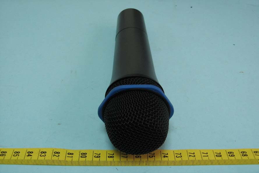
Click to zoom
Application Details
- Equipment Class
- DXX - Part 15 Low Power Communication Device Transmitter
- Date of Grant
- Dec 28, 2011
- Application Purpose
- Original Equipment
- Date of Application
- Dec 28, 2011
- Equipment Note
- Guide Microphone
- Frequency Range
- 909.50000000 - 914.50000000
- Company
- Elvex Corporation
- Country
- United States
Documents & Files
Document Text
Text extracted from the exhibit documents filed with the FCC. Open a document above to read the original.
Users Manual
Elvex Corporation, 13 Trowbridge Drive, Bethel, CT 06801, USA Phone: 203-743-2488, Email: 203-791-2278, Website: www.elvex.com User Instructions Elvex Guide System Products covered by this user instruction: Com-690, Guide Transceiver Headset Com-691, Guide Receiver Headset Com-699, Guide Microphone Elvex Guide System is a communications ear muffs set consisting of transceiver and receiver units, and a hand held microphone. All headsets are hearing protectors with an independently verified 22 dB NRR (Noise Reduction Rating). The transceiver can transmit and receive, while the receiver can only receive. The transmission range is up to 25 meters (77 feet) in ideal conditions, when no barriers or obstacles interfere with transmission. Potential applications: • Guided tours in noisy environments: A person can guide a group of individuals through a plant, explaining a process or technology. • A group participant can use the Guide Microphone to ask the guide a question. • Two individuals may communicate in a noisy environment by using two transceivers. Controls, Transceiver and Receiver: • The receiving channel selector has three available channels. Select the same channel # for transmitting on the transceiver and for receiving on the receiver headsets. Select another channel (for both) only if you experience interference. • The receiving channels are selected with the large circular button. The transmitting channel is selected with the button next to the battery compartment. • The on/off/volume control activates and deactivates the headset and also adjusts the volume. • The AMP button allows the user to increase the sound level of the receiver by 15 dB. This makes it possible to use the headset in environments with noise levels up to 105-110 db. Warning: when amplification is used the headset is no longer a hearing protector. The headset still provides 22 dB NRR, but the sound level inside the headset it too loud to provide effective hearing protection. • The microphone is noise canceling and voice activated and mounted on a flexible stalk. Adjust the microphone so that is sits very close to your mouth in order to have the best performance. Elvex Corporation, 13 Trowbridge Drive, Bethel, CT 06801, USA Phone: 203-743-2488, Email: 203-791-2278, Website: www.elvex.com Controls, Transceiver only: • The on/off/volume control activates and deactivates the headset, and it must be activated for the transmission to work. This setup allows the headset to be turned off with the on/off/volume button. • The transmitter channel (three channels are available) is selected with the button next to the battery compartment. Select the same channel # for transmitting on the transceiver and for receiving on the receiver headsets. Select another channel only if you experience interference. • To transmit: Depress the transmit button to put the transceiver in transmission mode. It transmits continuously. This feature may be useful if the guide application described above. When short communications are required, push the button to talk and push it again to end the transmission. The microphone is noise activated, and will go into sleep mode if no voice is heard for one minute. This is done to conserve battery life. Battery life and replacement: • The LED light next to the battery compartment will start to flash when the batteries have about 20 minutes of life expectancy. • Batteries are located in the battery compartment in the ear cup w/o controls. Both headset models use two AA batteries. Transceiver: In constant transmission mode the batteries will last approximately 2 hours. When transmission is made only occasionally battery life is extended significantly, and may exceed 10 hours. The transceiver is equipped with a voice activated microphone, why the battery life will normally fall in the middle of the range, or 5-6 hours. Receiver: Battery life can be expected to be about 40 hours. • In order to replace the batteries, open the battery lid and remove the old batteries. Insert new batteries, and observe that the polarization is correct, with the (+) on the batteries matching up with the (+) on the battery housing. Replace the battery lid, and make sure that it locks in with a distinctive snap. Handheld microphone • The handheld microphone can transmit to both the transceiver and the receiver headsets. Transmitting channels can be changed by removing the battery cover, and setting the channel switch. • Unscrew the microphone base, in order to insert two AA batteries, making sure the polarization is correct. • Battery life can be expected to be 2-4 hours when transmitting, depending on the situation. • The microphone can be used in a guide application, providing an avenue for visitors (using receivers) to ask questions of the guide (using a transceiver). • Observe: The microphone cannot transmit simultaneously with the transceiver on the same channel, since this will cause interference. The microphone can transmit to the transceivers receiving channel while the transceiver is on. If the transceiver is used to guide a group, the guide has to repeat the question to the group. Elvex Corporation, 13 Trowbridge Drive, Bethel, CT 06801, USA Phone: 203-743-2488, Email: 203-791-2278, Website: www.elvex.com FCC required notices: Model:Com-699 FCC ID:ZADCOM699 • This device complies with part 15 of the FCC Rules. Operation is subject to the following two conditions: (1) This device may not cause harmful interference, and (2) this device must accept any interference received, including interference that may cause undesired operation. • NOTICE: The changes or modifications expressly approved by the party responsible for compliance could void the users authority to operate the equipment • IMPORTANT NOTE: To comply with the FCC RF exposure compliance requirements, no change to antennae or the device is permitted. Any change to the antenna or the device could result in the device exceeding the RF exposure requirements and void users…
Text truncated - open the document above for the full version.
Cover Letter(s)
ILVEX Mzbmto\~\\ pliiCnS vices Cetionision 47173BiciaSt FmooCA94538USA t-: To whomit maycor We.the undersigr'yat ELERONICSTAIWANt on our lfinallmg apptionforequt including singofalldmmatyandaby ELECTRONICSτSτ GTAIWANon our shallhavethe me effect actsof our own. Wundersighbythatweare notEa nialoffel~a includesFCCbenn 5301of the Ause t of 1988.21 S.C. 853(a). mrizingELECTRONICSINGCENTERTAIWANasonr~westillgs thatweareronsibleto: a)mplywtherelev;provisionsof the cer npro b)makeall nsaryarrangeentsforthe.elofeevmtioincluding provisionfor exgd end Cstoall arre [mcludinginnalauditrepod personnelfor the purposesof ata (einsmveimd Junon ofωpints; c)makeclmsrerdingcationonlyrespectof es pe rw ch certinonhbn grant donotuourproducteel.tionchambringe onDisiondisrluted not makeanystem·t g ourpructcernw eCeron visionmayInsider mislldingormuthorizc e)"n sionoreUationof diontinueufall adver19mnsanyd tuma cationdriredbythe onDi unononlyto indicatethe productsare certifiedbeingin conformitywithifiedsdds; g)endeavorce5te or reportnor any partthereofis usedin a misleadingmanner; h)ensurethaty referenceto our productficationin communicationmedia suchdumentsbrochuror advertisingmpwiththe requirents oftheCe6.tionDivision; i)klp a recordof aU complaintsmadeknownto the us relatingto the product's compliancewithrequirementsof the relevantstandardandto makethese recordsavailableto the CertificationDivisionwhenrequested; j)takeappropriateactionwithrespectto suchmplaintsandany deficiencies foundin productsor servicesthataffiωmp}withthe requirementsr certltion; documentthe tionstak s authorizationis validuntilfurtherwrittennotim the applicant. SinlyYou i FredvetVicePresident Elvexrporation 13TrowbridgeDrive BetheCT 06801 .' -
External Photos
ETC Report No. : 11-01-RBF-018 Sheet 1 of 6 Sheets FCC ID.: ZADCOM699 Rev. No 2.0 CONSTRUCTED PHOTOS of EUT 1. Top View of EUT 2. Bottom View of EUT ETC Report No. : 11-01-RBF-018 Sheet 2 of 6 Sheets FCC ID.: ZADCOM699 Rev. No 2.0 CONSTRUCTED PHOTOS of EUT 3. Side View of EUT 4. Front View of EUT ETC Report No. : 11-01-RBF-018 Sheet 3 of 6 Sheets FCC ID.: ZADCOM699 Rev. No 2.0 CONSTRUCTED PHOTOS of EUT 5. Side View of EUT 6. Rear View of EUT
ID Label/Location Info
4.5cm 1.2 cm Model:Com-699 FCC ID:ZADCOM699 • This device complies with part 15 of the FCC Rules. Operation is subject to the following two conditions: (1) This device may not cause harmful interference, and (2) this device must accept any interference received, including interference that may cause undesired operation.
Internal Photos
ETC Report No. : 11-01-RBF-018 Sheet 4 of 6 Sheets FCC ID.: ZADCOM699 Rev. No 2.0 CONSTRUCTED PHOTOS of EUT 7. Internal View of EUT 8. Internal View of EUT ETC Report No. : 11-01-RBF-018 Sheet 5 of 6 Sheets FCC ID.: ZADCOM699 Rev. No 2.0 CONSTRUCTED PHOTOS of EUT 9. Solder View of PCB 10. Component View of PCB ETC Report No. : 11-01-RBF-018 Sheet 6 of 6 Sheets FCC ID.: ZADCOM699 Rev. No 2.0 CONSTRUCTED PHOTOS of EUT 11. Solder View of PCB
Test Report
Rev. No 2.0 FCC Part 15 EMI TEST REPORT of E.U.T. : Guide Microphone MODEL : Com-699 FCC ID. : ZADCOM699 for APPLICANT : Elvex Corporation ADDRESS : 13 Trowbridge Drive Bethel, CT USA Test Performed by ELECTRONICS TESTING CENTER, TAIWAN NO. 34. LIN 5. DINGFU, LINKOU DIST., NEW TAIPEI CITY, TAIWAN, 24442, R.O.C. TEL : (02)26023052 FAX: (02)26010910 http : // www.etc.org.tw; e-mail : [email protected] Report Number : 11-01-RBF-018 ETC Report No. : 11-01-RBF-018 FCC ID. : ZADCOM699 Rev. No 2.0 TEST REPORT CERTIFICATION Applicant : Elvex Corporation 13 Trowbridge Drive Bethel, CT USA Manufacturer : Elvex Corporation 13 Trowbridge Drive Bethel, CT USA Description of EUT a) Type of EUT : Guide Microphone b) Trade Name : Guide Microphone, Com-699 c) Model No. : Com-699 d) Power Supply : DC1.5V battery *2 e) Frequency Range : 909.5MHz - 914.5MHz Regulation Applied : FCC Rules and Regulations Part 15 Subpart C I HEREBY CERTIFY THAT: The data shown in this report were made in accordance with the procedures given in ANSI C63.4, and the energy emitted by the device was founded to be within the limits applicable. I assume full responsibility for accuracy and completeness of these data. Note: 1. The result of the testing report relate only to the item tested. 2. The testing report shall not be reproduced expect in full, without the written approval of ETC. Issued Date : Feb. 15, 2011 Test Engineer : ( Falcon Shi, Engineer ) Check By : ( Charles Wang, Supervisor ) Approve & Authorized Signer : Will Yauo, Manager EMC Dept. II of ELECTRONICS TESTING CENTER, TAIWAN ETC Report No. : 11-01-RBF-018 FCC ID. : ZADCOM699 Rev. No 2.0 Table of Contents Page 1 GENERAL INFORMATION ...................................................................................................... 1 1.1 Product Description...................................................................................................................... 1 1.2 Characteristics of Device ............................................................................................................. 1 1.3 Test Methodology......................................................................................................................... 1 1.4 Test Facility.................................................................................................................................. 1 2 PROVISIONS APPLICABLE ..................................................................................................... 2 2.1 Definition ..................................................................................................................................... 2 2.2 Requirement for Compliance ....................................................................................................... 3 2.3 Restricted Bands of Operation ..................................................................................................... 5 2.4 Labeling Requirement .................................................................................................................. 5 2.5 User Information .......................................................................................................................... 6 3. SYSTEM TEST CONFIGURATION ......................................................................................... 7 3.1 Justification .................................................................................................................................. 7 3.2 Devices for Tested System ........................................................................................................... 7 4 RADIATED EMISSION MEASUREMENT ............................................................................. 8 4.1 Applicable Standard ..................................................................................................................... 8 4.2 Measurement Procedure ............................................................................................................... 8 4.3 Measuring Instrument................................................................................................................. 11 4.4 Radiated Emission Data ............................................................................................................. 12 4.4.1 RF Portion ......................................................................................................................................... 12 4.4.2 Other Emissions ................................................................................................................................. 15 4.5 Field Strength Calculation.......................................................................................................... 15 4.6 Photos of Radiation Measuring Setup ........................................................................................ 16 5 CONDUCTED EMISSION MEASUREMENT ....................................................................... 17 5.1 Description ................................................................................................................................. 17 6 ANTENNA REQUIREMENT ................................................................................................... 18 6.1 Standard Applicable ................................................................................................................... 18 6.2 Antenna Construction................................................................................................................. 18 7 BAND EDGES MEASUREMENT ............................................................................................ 19 7.1 Standard Applicable ................................................................................................................... 19 7.2 Measurement Procedure ............................................................................................................. 19 7.3 Measurement Equipment..........................…
Text truncated - open the document above for the full version.
Test Setup Photos
ETC Report No. : 11-01-RBF-018 Sheet 16 of 22 Sheets FCC ID.: ZADCOM699 Rev. No 2.0 4.6 Photos of Radiation Measuring Setup
Contact Information
Applicant
Fred Ravetto(Vice President)
Test Firm
Taiwan Testing and Certification CenterAnderson Ku
Technical Specifications
| # | Rule Parts | Frequency Range | Power Output |
|---|---|---|---|
| 1 | 15C | 909.5 MHz - 914.5 MHz | - |
Other Applications from Elvex Corporation
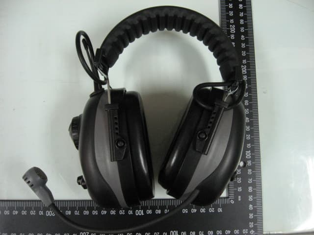
ZADCOM690
Apr 11, 2012Guide Transceiver
Equipment Class
DXT - Part 15 Low Power Transceiver, Rx Verified