ZAKLIB-V1000ELiberator V100/V1000 Wireless Ethernet Bridge
Sub10 Systems Ltd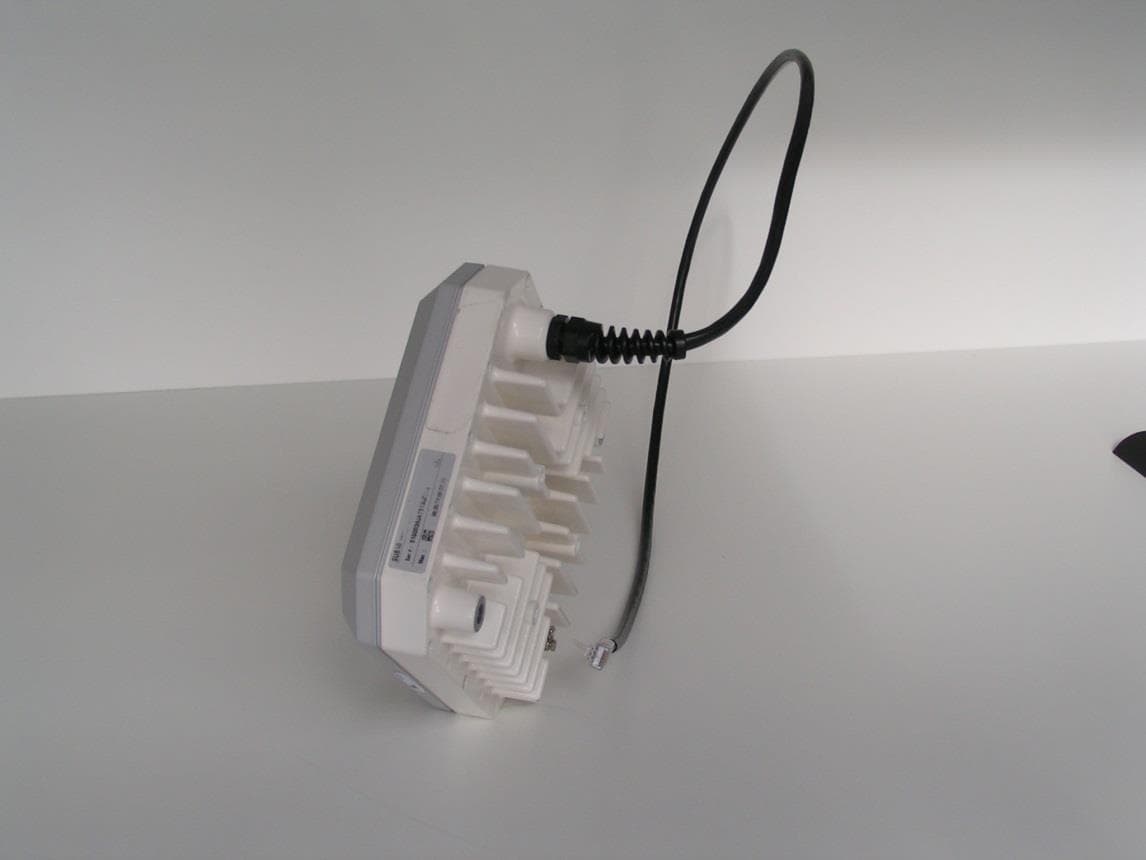
Click to zoom
Application Details
- Equipment Class
- DXX - Part 15 Low Power Communication Device Transmitter
- Date of Grant
- May 05, 2014
- Application Purpose
- Original Equipment
- Date of Application
- Apr 08, 2014
- Equipment Note
- Liberator V100/V1000 Wireless Ethernet Bridge
- Frequency Range
- 61500.00000000 - 62500.00000000
- Company
- Sub10 Systems Ltd
- Country
- United Kingdom
Documents & Files
Document Text
Text extracted from the exhibit documents filed with the FCC. Open a document above to read the original.
Users Manual
Liberator-V1000 Manual Rev 00v01 Page 1 Sub10 Systems Liberator-V1000 Installation & User Manual Revision 00v01 Firmware – v02.01.01.03 Page 2 Sub10 Systems Document Type User Manual Project Liberator-V1000 Date 2 April 2014 Authors Malcolm Sellars Title V1000 Installation & User Manual Classification Sub10 Systems Public Document Number SUB10-0098_00v02 Liberator-V1000 Manual Rev 00v01 Page 3 Sub10 Systems Version Date Author Description 00v01 2 April 2014 M. Sellars Release 02.01.01.03 00v02 8 April 2014 C. Fisher Additional FCC regulatory requirements in Annex B Page 4 Sub10 Systems 1 INTRODUCTION .................................................................................................................................... 5 1.1 Revision ............................................................................................................................................ 5 1.2 Intended users & Software Version ................................................................................................. 5 1.3 Safety Information ............................................................................................................................ 5 1.4 Warranty ........................................................................................................................................... 6 1.5 Copyright / Disclaimer ..................................................................................................................... 6 2 SYSTEM OVERVIEW .............................................................................................................................. 7 2.1 Top Level Description ...................................................................................................................... 7 2.2 Ethernet switch ................................................................................................................................ 8 2.3 Package contents............................................................................................................................. 9 2.4 Accessories and Spares (available to order as additional parts) .................................................12 3 SITE PLANNING .................................................................................................................................. 13 3.1 Terminal location ............................................................................................................................13 3.2 Line of sight ....................................................................................................................................13 3.3 Link distance / Link availability ......................................................................................................14 3.4 Terminal Mounting Options ............................................................................................................14 3.5 Lightning Protection Zones ............................................................................................................14 3.6 Cabling ............................................................................................................................................15 3.7 Co-located applications ..................................................................................................................15 4 Installation ......................................................................................................................................... 16 4.1 Installation Details ..........................................................................................................................16 4.2 Terminal installation .......................................................................................................................17 4.3 Grounding .......................................................................................................................................20 4.4 Lightning / Surge protector ............................................................................................................21 4.5 RJ45 Seal Kit ...................................................................................................................................22 4.6 Cable installation ............................................................................................................................22 4.7 Power injector .................................................................................................................................22 4.8 Antenna alignment ..........................................................................................................................23 4.9 Factory-Defaulting a Terminal ........................................................................................................28 4.10 Maintenance ..................................................................................................................................29 5. Web Management Interface ............................................................................................................. 30 5.1 Login Page ......................................................................................................................................30 5.2 Home Page ......................................................................................................................................31 5.3 Operation .........................................................................................................................................32 5.4 Administration .................................................................................................................................35 5.5 Maintenance ....................................................................................................................................47 6 SNMP Management Interface ....................................................…
Text truncated - open the document above for the full version.
External Photos
Figure 1: Front view of the unit showing the Antenna Face Figure 2: Reard View of the unit showing the Cable Entry and Heatsink Arrangement
ID Label/Location Info
Figure 3: Lable Location (Using Liberator-V1000 as example of both Liberator-V100 and Liberator- V1000)
Internal Photos
Figure 1 : Front View of Antenna Assembly Figure 2: Internal View of Antenna Assembly Figure 3: A/B Band Diplexers (Antenna Face) Figure 4: A/B Band Diplexers (Radio Side) Figure 5: Component Side of Common Modem Board Figure 6 : Reverse Side of Common Modem Board Figure 7: A Band Microwave Board Figure 8 B Band Microwave Board Figure 9: Inside View of Heatsink/Chassis Figure 10: Modem and Microwave Assembly into Heatsink
RF Exposure Info
Title: V100/V1000 Technical Description Page 1 of 5 Document Type: Technical Report Document Number: SUB10-0100_00v01 Classification: Sub10 Confidential Document Type Technical Report Project Liberator-V100 and Liberator-V1000 Date 26 March 2014 Author Clem Fisher Title Human Safety Assessment against FCC OET Bulletin 65 Classification Sub10 Confidential Abstract This report contains the results of evaluating the Liberator product range against the requirements of FCC OET Bulletin 65 and recommends minimum separation distances from the product to the general public in all installations. The recommendations of this analysis are included in the User Manual for the products. Title: V100/V1000 Technical Description Page 2 of 5 Document Type: Technical Report Document Number: SUB10-0100_00v01 Classification: Sub10 Confidential Revision History Version Date Author Description 00V01 26 March 2014 Clem Fisher First Draft Title: V100/V1000 Technical Description Page 3 of 5 Document Type: Technical Report Document Number: SUB10-0100_00v01 Classification: Sub10 Confidential Contents 1 Scope ......................................................................................................................................... 4 2 Reference Documents ................................................................................................................ 4 3 Applicable Limits......................................................................................................................... 4 4 Results of Analysis ..................................................................................................................... 5 5 Recommendation ....................................................................................................................... 5 Title: V100/V1000 Technical Description Page 4 of 5 Document Type: Technical Report Document Number: SUB10-0100_00v01 Classification: Sub10 Confidential 1 Scope This report contains the results of evaluating the Liberator product range against the requirements of FCC OET Bulletin 65 and recommends minimum separation distances from the product to the general public in all installations 2 Reference Documents There are regulations defining limits for exposure of the general public to non-ionising radiation which are produced by radio transmitters. This is called RF Exposure The documents applicable here are : [1] US Code of Federal Regulations, in particlar the policies, guidelines and requirements in Part 1 of Title 47 of the CF. See (www.fcc.gov) [2] Guidelines and reccomendations for evaluating compliance contained in FCC Bulletin 65 [3] ICNIRP Guidelines for Limiting Exposure to Time Varying Electric, Magnetic and Electromagnetic Fields (up to 300 GHz); see www.icnirp.de/ [4] Safety Code 6 on the Health Canada Website www.hc-sc.gc/ca/ 3 Applicable Limits The limits to be applied depend on the operating frequency of the transmitter All the reference documents agree that exposure limits for the general public in the band around 60GHz are that the applicable limit should be the RF Power Density level. The general population should not be exposed to a level ≥10W/m 2 . Reference [2] provides a simple method of calculating the exposure level at different separation distances and this can be used to identify the minimum separation distance from the product to any member of the general public Where: RF Power Density (S) in metre Transmitted Power (P) in Watt Antenna Gain (G) as a linear number Separation distance in metre Title: V100/V1000 Technical Description Page 5 of 5 Document Type: Technical Report Document Number: SUB10-0100_00v01 Classification: Sub10 Confidential 4 Results of Analysis The power levels used below are the maximum levels recorded in the Formal Test Report to Part 15.255_TRA-015579WUS1 from TRaC Global. Antenna Gain Maximum Power Level Separation Distance (m) for S = 10W/m2 Recommended Separation Distance (m) Operating Mode dBi Linear dBm W V100 38 6310 11.6 0.0145 0.85 1 V1000 38 6310 10.9 0.0123 0.79 1 At the recommended separation distance, the power density is 1.4 to 1.6 times lower than the limit. Note The analysis above is very conservative as it is based on point source radiation and not a practical point to point, narrow beam antenna. It should be noted that the full antenna gain of 38dBi is not achieved until the separation distance is 6m or more 5 Recommendation Sub10 Systems recommends (in its User Guide) that a minimum separation distance of 1m (from the equipment to the general public) should be ensured in all installations
Test Report
TRaC RADIO TEST REPORT FOR Sub10 Systems Limited ON Liberator-V1000 DOCUMENT NO. TRA-015579-W-US-1b TRaC Radio Test Report: TRA- TRA-015579-W-US-1b 2 TRaC Wireless Test Report : TRA-015579-W-US-1b Applicant : Sub10 Systems Limited Apparatus : Liberator-V1000 Specification(s) : CFR47 Part15 C 15.255: October 2012 Purpose of Test : Certification Authorised by : : Radio Product Manager Issue Date : 8 th August 2014 Authorised Copy Number : PDF Total number of pages : 86 TRaC Radio Test Report: TRA-015579-W-US-1b 3 Contents Section 1: Introduction 4 1.1 General 4 1.2 Tests Requested By 5 1.3 Manufacturer 5 1.4 Apparatus Assessed 6 1.5 Test Result Summary 7 1.6 Notes Relating To The Assessment 8 1.7 Deviations from Test Standards 8 Section 2: Measurement Uncertainty 9 2.1 Measurement Uncertainty Values 9 Section 3: Modifications 10 3.1 Modifications Performed During Assessment 10 Appendix A: Formal Emission Test Results 11 A1 Frequency Stability 12 A2 Transmitter Power Limitation 16 A3 Transmitter Peak Power (Conducted) 18 A4 Transmit Radiated Electric Field Emissions 20 A6 ac Power Line Conducted Emissions (15.207) 23 A7 Unintentional Radiated Electric Field Emissions - 15.109 (Receiver/Digital circuitry) 25 Appendix B: Supporting Graphical Data 26 Appendix C: Additional Test and Sample Details 76 Appendix D: Additional Information 82 Appendix E: Photographs and Figures 84 TRaC Radio Test Report: TRA-015579-W-US-1b 4 Section 1: Introduction 1.1 General This report contains an assessment of an apparatus against Radio Standards based upon tests carried out on samples submitted to the Laboratory. Test performed at: TRaC Global [ X ] Unit E South Orbital Trading Park Hedon Road Hull, HU9 1NJ. United Kingdom. Telephone: +44 (0) 1482 801801 Fax: +44 (0) 1482 801806 TRaC Global [ ] Moss View Nipe Lane Up Holland West Lancashire, WN8 9PY United Kingdom Telephone: +44 (0) 1695 556666 Fax: +44 (0) 1695 577077 Email: [email protected] Web site: http://www.tracglobal.com Tests performed by: K J Anderson Report author: K J Anderson This report must not be reproduced except in full without prior written permission from TRaC Global Ltd. TRaC Radio Test Report: TRA-015579-W-US-1b 5 1.2 Tests Requested By This testing in this report was requested by: Sub10 Systems Limited Ash House Canal Way Kingsteignton Newton Abbot TQ12 3RZ United Kingdom 1.3 Manufacturer As above TRaC Radio Test Report: TRA-015579-W-US-1b 6 1.4 Apparatus Assessed The following apparatus was assessed between 27/01/14 and 15/07/14 Liberator-V1000 The apparatus is a point to point full duplex wireless data link operating in the 57 GHz to 64 GHz band. The EUT is fitted with an Integral Antenna which has a gain of 38dBi. The equipment will operate in a 100 MB/s mode with a 100 MHz channel bandwidth referred to as V100 mode in this report and in a 1GB/s mode with a 500 MHz channel bandwidth referred to as V1000 mode in this report. TRaC Radio Test Report: TRA-015579-W-US-1b 7 1.5 Test Result Summary Full details of test results are contained within Appendix A. The following table summarises the results of the assessment. The statements relating to compliance with the standards below apply ONLY as qualified in the notes and deviations stated in sections 1.6 to 1.7 of this test report. Full details of test results are contained within Appendix A. The following table summarises the results of the assessment. Test Type Regulation Measurement standard Result Frequency Stability Title 47 of the CFR: Part 15 Subpart C; 15.255 (f) TIA-603C Pass Harmonics and Spurious Emissions Title 47 of the CFR: Part 15 Subpart C; 15.255 (c) TIA-603C Pass Transmitter Power Limitation Title 47 of the CFR: Part 15 Subpart C; 15.255 (b) (1) TIA-603C (Note) Pass Transmitter Peak Power (conducted) Title 47 of the CFR: Part 101 Subpart C; 15.255 (e) TIA-603C (Note) Pass Power Line Conducted emissions Title 47 of the CFR: Part 15 Subpart b; 15.107 ANSI C63.4 Pass Spurious emissions from digital circuitry Title 47 of the CFR: Part 15 Subpart b; 15.109 ANSI C63.4 Pass RF Exposure Title 47 of the CFR: Part 2 ; 2.1093 - Pass Note: The fundamental power for the EUT was measured according to the FCC Rule Section 15.255 using the measurement procedure in KDB200443 TRaC Radio Test Report: TRA-015579-W-US-1b 8 1.6 Notes Relating To The Assessment With regard to this assessment, the following points should be noted: The results contained in this report relate only to the items tested and were obtained in the period between the date of initial receipt of samples and the date of issue of the report. The apparatus was set up and exercised using the configurations, modes of operation and arrangements defined in this report only. Particular operating modes, apparatus monitoring methods and performance criteria required by the standards tested to have been performed except where identified in Section 1.7 of this test report (Deviations from Test Standards). For emissions testing, throughout this test report, “Pass” indicates that the results for the sample as tested were below the specified limit (refer also to Section 2, Measurement Uncertainty). Where relevant, the apparatus was only assessed using the monitoring methods and susceptibility criteria defined in this report. All testing with the exception of testing at the Open Area Test Site was performed under the following environmental conditions: Temperature : 17 to 23 °C Humidity : 45 to 75 % Barometric Pressure : 86 to 106 kPa All dates used in this report are in the format dd/mm/yy. This assessment has been performed in accordance with the requirements of ISO/IEC 17025. 1.7 Deviations from Test Standards There were no deviations from the standards tested to. TRaC Radio Test Report: TRA-015579-W-US-1b 9 Section 2: Measurement Uncertainty 2.1 Measurement Uncertainty Values For test data recorded, the following measurement uncertainty was calculated: Radiated Electric Field Emissions Quantity Range Quantity Expanded Uncertainty 9kHz…
Text truncated - open the document above for the full version.
Contact Information
Applicant
Mark Stevens(Chief Technical Officer)
Test Firm
Element Materials Technology Warwick LtdMax Leach
Technical Specifications
| # | Rule Parts | Frequency Range | Power Output |
|---|---|---|---|
| 2 | 15C | 61.50 GHz - 62.50 GHz | - |