ZBL20140Automotive Remote Keyless Security System
Riverside Mfg., LLC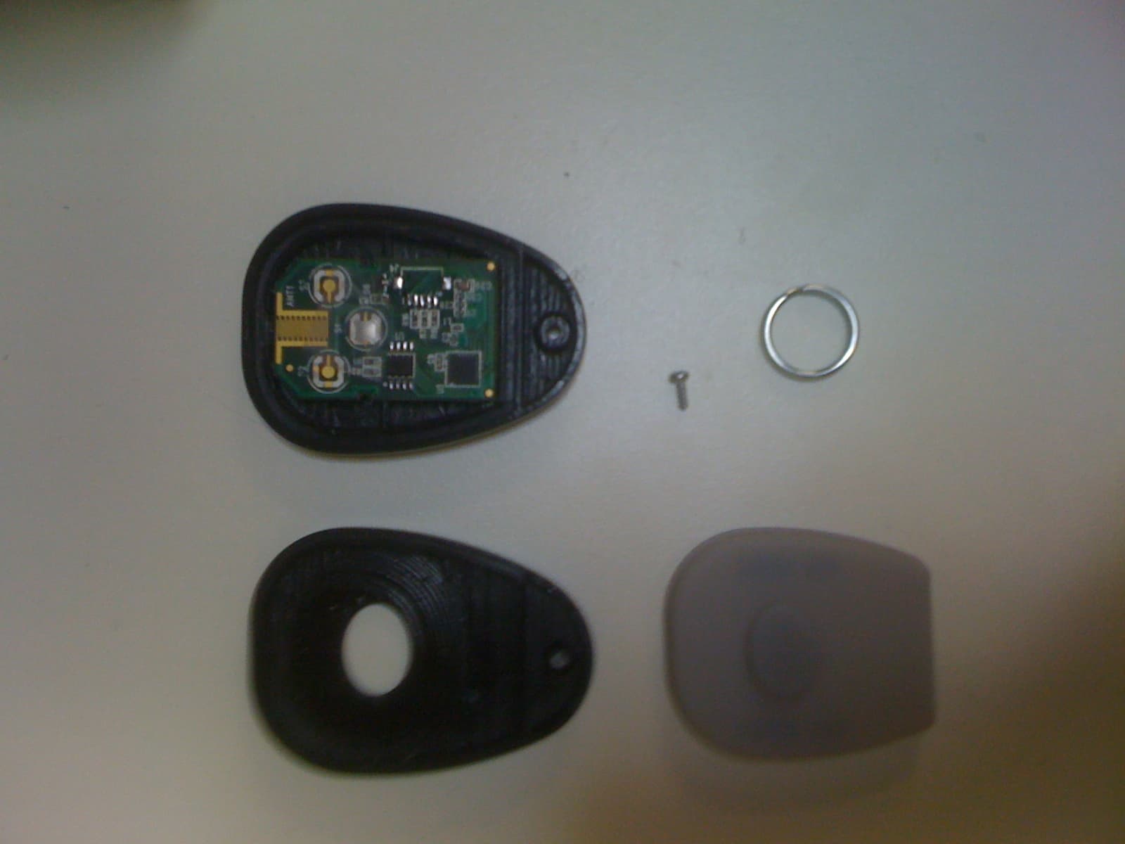
Click to zoom
Application Details
- Equipment Class
- DSC - Part 15 Security/Remote Control Transmitter
- Date of Grant
- Mar 16, 2011
- Application Purpose
- Original Equipment
- Date of Application
- Mar 16, 2011
- Equipment Note
- Automotive Remote Keyless Security System
- Frequency Range
- 433.92000000 - 433.92000000
- Company
- Riverside Mfg., LLC
- Country
- United States
Documents & Files
Document Text
Text extracted from the exhibit documents filed with the FCC. Open a document above to read the original.
Users Manual
Utilimaster Access System User’s Guide Feb. 28, 2011 14510 LIMA ROAD. FORT WAYNE, IN 46818 PHONE (260) 637-4470 FAX (260) 637-4472 Notes to the user: This device complies with part 15 of the FCC Rules. Operation is subject to the following two conditions: (1) This device may not cause harmful interference, and (2) this device must accept any interference received, including interference that may cause undesired operation. Changes or modifications not expressly approved by the manufacturer could void the user’s authority to operate the equipment. The installer of this radio equipment must ensure that the antenna is located or pointed such that it does not emit RF field in excess of Health Canada limits for the general population; consult Safety Code 6, obtainable from Health Canada’s website www.hc-sc.gs.ca/rpb This product uses FreeRTOS Version 6.1.0 – © 2010 Real Time Engineers Ltd. Source code for FreeRTOS is available free at www.freertos.org , and will be provided upon request in accordance with the GPL Exception clause. 14510 LIMA ROAD. FORT WAYNE, IN 46818 PHONE (260) 637-4470 FAX (260) 637-4472 System Overview Single Button RF Remote o 25-50+ Range o 6 Month estimated battery life (CR2032 coin cell) o Custom tooled, sealed plastic housing o 5,000,000 cycle switch life o Digital encryption Engine Start/Stop control (Start/Stop switch NOT provided as part of this system) Cargo and Bulkhead door latch activation USB Thumb-drive updateable System Heartbeat and Status LEDs Up to 16 remotes may be enrolled to a truck A remote may be enrolled to an unlimited number of trucks System Inputs and Outputs 2x 10A (+12V) Smart FET outputs (Latch Solenoid Drivers) o Cargo Door o Bulkhead Door o 2 Spares 4x 1A (+12V) FET outputs o ACC Relay Driver o START Relay Driver o RUN Relay Driver o GND Relay Driver o Switch Backlight 2x +12V Active Digital Inputs o Start Switch Input o Stop Switch Input o USB port for thumb drive updates/reconfiguration 14510 LIMA ROAD. FORT WAYNE, IN 46818 PHONE (260) 637-4470 FAX (260) 637-4472 System Operation Engine Start 1) Press the transmitter button on the key fob once to activate ignition. The green light on the Start button will flash to acknowledge the fob. 2) Within 8 seconds, tap the green Start button on the dash to turn the ignition on. The green light will turn on solid. 3) Within 5 seconds, press and hold the Start button to crank the engine until it starts. 4) If the engine doesn’t start, you may try restarting it again within 5 seconds of releasing the Start button. After 5 seconds from the time you release the Start button, the controller will assume the engine is running and disable the Start function. Engine Stop 1) When the engine is running, press the red Stop button for ½ second to stop the engine. Bulkhead Door Quick Open 1) Use the Stop button to stop the engine when it is running. 2) Within 5 seconds after stopping the engine, press the Stop button a second time to open the Bulkhead Door (latch will activate for 2 seconds). Bulkhead Door Remote Open 1) Press and hold the button on the key fob for 2 seconds. 2) The Bulkhead door solenoid will activate for 2 seconds, allowing the door to be opened. Cargo Door Open 1) “Double-click” the button on the key fob. 2) The Cargo door solenoid will activate for 8 seconds, allowing the door to be opened. Key Fob Enrollment 1) Stop the vehicle and turn off the engine. 2) Using a fob currently programmed to the vehicle, press the button once to prompt the Ready mode (blinking flash). 3) Press and hold the Stop button for 5 seconds to enter Learn Mode. The switch lights will “flicker flash” to indicate that it is in Learn Mode. 4) Release the switch. 5) Press the button on the fob to be added. The Start switch will double flash to acknowledge the fob, and then immediately exit the Learn mode. 6) Test the fob to verify that it has been added correctly. 7) Repeat step 1-5 to enroll another fob (up to 16 per truck). 14510 LIMA ROAD. FORT WAYNE, IN 46818 PHONE (260) 637-4470 FAX (260) 637-4472 Erase All Remotes 1) Stop the vehicle and turn off the engine. 2) Using a fob currently programmed to the vehicle, press the button once to prompt the Ready mode (blinking flash). 3) Press and hold the Stop button for 20 seconds to erase all fobs except the one that was used to initiate this procedure in step 2. The switch lights will double flash and exit the Erase mode automatically. Manual Erase All and Enroll Remotes 1) Stop the vehicle and turn off the engine. 2) Open the controller module enclosure. 3) Press and hold the button SW1 for 20 seconds. The red and green LEDs will turn on to indicate that all fobs have been erased. Do not let go of the button 4) Continue to hold the button for 1 ½ minutes. The red and green LEDs will start blinking to indicate the system is in Learn mode. 5) Release the button. 6) Press the button on the fob to be added. The red and green LEDs on the circuit board, as well as the Ignition switch will double flash to acknowledge the fob has been added. The system will immediately exit the Learn mode. 7) Test the fob to verify that it has been added correctly. 8) Reassemble and reinstall the controller module. 9) Additional fobs may now be added using the standard enrollment process.
Cover Letter(s)
14510 LIMA ROAD. FORT WAYNE, IN 46818 PHONE (260) 637-4470 FAX (260) 637-4472 March 10, 2011 FCC ID: ZBL-20140 Request for Confidentiality In accordance with 47 C.F.R. Section 0.459, we, Riverside Mfg., LLC, hereby request confidentiality for the block diagram, schematic and product description presented for certification. In support of the Request for Confidentiality, the following is stated: Enclosed within this application is technical information which we deem to be trade secrets and proprietary. If made public, the information might be used to our disadvantage. To assist in assuring that we receive the full value of our product and protect its competitive posture, we respectfully request this grant of confidentiality. John Reid Riverside Mfg., LLC
ID Label/Location Info
1 1 2 2 3 3 4 4 5 5 6 6 7 7 8 8 AA BB CC DD EE FF MFG., LLC. LABEL, FCC ID UTILIMASTER UAS FORT WAYNE, IN 15237 SIZECAGE CODE B 4U3K2 REV - SCALE 2:1 SHEET 115237.REL.idw UNLESS OTHERWISE SPECIFIED DIMENSIONS ARE IN INCHES. TOLERANCES ON DWN BY K.BECKER 2/15/2011 3/9/2011 D.REDNOUR CHK BY ENGR APR MFG APR .XX DEC .XXX DEC ANGLE .03.005 .5 Released DRAWING STATE SOLE SOURCE VENDOR ~ ``` Copyright and Proprietary Information.Copyright © 2010 Riverside Mfg LLC. All Rights Reserved. THIS DOCUMENT IS THE PROPERTY OF RIVERSIDE MFG LLC. AND CONTAINS PROPRIETARY INFORMATION OF RIVERSIDE MFG LLC. DO NOT COPY, STORE IN A RETRIEVAL SYSTEM, TRANSMIT, OR DISCLOSE TO ANY THIRD PARTY WITHOUT THE PRIOR WRITTEN PERMISSION FROM AN OFFICER OF RIVERSIDE MFG LLC. REVISION HISTORY ZONEREVDESCRIPTIONDATEAPPROVED -- RELEASE 2/15/2011 K.BECKER NOTES: 1. MATERIAL: POLYESTER LABEL STOCK WITH PERMANENT ACRYLIC ADHESIVE 2. COLOR: BLACK TEXT ON WHITE BACKGROUND 3. MUST BE INDELIBLY PRINTED. .75 1.00 R.06 TYP .082 .060 TYP
ID Label/Location Info
1 1 2 2 3 3 4 4 5 5 6 6 7 7 8 8 AA BB CC DD EE FF MFG., LLC. KEY FOB ASSY, REMOTE UTILIMASTER UAS FORT WAYNE, IN 20140 SIZECAGE CODE B 4U3K2 REV - SCALE 1=1 SHEET 120140.REL.idw UNLESS OTHERWISE SPECIFIED DIMENSIONS ARE IN INCHES. TOLERANCES ON DWN BY K.BECKER 1/10/2011 2/10/2011 D.REDNOUR CHK BY ENGR APR MFG APR .XX DEC .XXX DEC ANGLE .03.005 .5 Released DRAWING STATE SOLE SOURCE VENDOR ~ ``` Copyright and Proprietary Information.Copyright © 2010 Riverside Mfg LLC. All Rights Reserved. THIS DOCUMENT IS THE PROPERTY OF RIVERSIDE MFG LLC. AND CONTAINS PROPRIETARY INFORMATION OF RIVERSIDE MFG LLC. DO NOT COPY, STORE IN A RETRIEVAL SYSTEM, TRANSMIT, OR DISCLOSE TO ANY THIRD PARTY WITHOUT THE PRIOR WRITTEN PERMISSION FROM AN OFFICER OF RIVERSIDE MFG LLC. DESCRIPTION PART NUMBER QTY ITEM PCB ASSY, UAS REMOTE15230-ASSY 11 KEY FOB, FRONT15234-112 KEY FOB. REAR15235 1 3 BUTTON, KEY FOB15236-114 SCREW, 2-28 X .375 TRI-LOBE90380A011 15 LABEL, FCC15237 17 BATTERY, COIN CELLCR20321 8 CARABINEER W/ SPLIT RING15242 1 9 2 4 3 1 7 5 9 REVISION HISTORY ZONEREVDESCRIPTIONDATEAPPROVED -- RELEASE 2/10/2011 K.BECKER 8
Test Report
Engineering Test Report No. 1100043-01 Measurement of RF Emissions from a 20140 Transmitter For Riverside Manufacturing, Inc. 14510 Lima Road Ft. Wayne, IN 46818 P.O. Number 84181 Date Tested February 22, 2011 Test Personnel Mark Longinotti Test Specification FCC "Code of Federal Regulations” Title 47 Part15, Subpart C Industry Canada RSS-GEN Industry Canada RSS-210 Test Report By: Mark Longinotti EMC Engineer Requested By: John Reid Riverside Manufacturing, Inc. Approved By: Raymond J. Klouda Registered Professional Engineer of Illinois - 44894 Elite Electronic Engineering, Inc. 1516 Centre Circle Downers Grove, IL 60515 Tel : (630) 495-9770 Fax: (630) 495-9785 www.elitetest.com Engineering Test Report No. 1100043-01 TABLE OF CONTENTS PARAGRAPH DESCRIPTION OF CONTENTS PAGE NO. THIS REPORT SHALL NOT BE REPRODUCED, EXCEPT IN FULL, WITHOUT THE WRITTEN APPROVAL OF ELITE ELECTRONIC ENGINEERING INCORPORATED. Page 2 of 22 1. Introduction ................................................................................................................................................... 4 1.1. Scope of Tests ..................................................................................................................................... 4 1.2. Purpose ............................................................................................................................................... 4 1.3. Deviations, Additions and Exclusions .................................................................................................. 4 1.4. EMC Laboratory Identification ............................................................................................................. 4 1.5. Laboratory Conditions.......................................................................................................................... 4 2. Applicable Documents .................................................................................................................................. 4 3. EUT Setup and Operation ............................................................................................................................ 5 3.1. General Description ............................................................................................................................. 5 3.1.1. Power Input ................................................................................................................................. 5 3.1.2. Peripheral Equipment ................................................................................................................. 5 3.1.3. Signal Input/Output Leads .......................................................................................................... 5 3.1.4. Grounding ................................................................................................................................... 5 3.2. Operational Mode ................................................................................................................................ 5 3.3. EUT Modifications ................................................................................................................................ 5 4. Test Facility and Test Instrumentation ......................................................................................................... 5 4.1. Shielded Enclosure .............................................................................................................................. 5 4.2. Test Instrumentation ............................................................................................................................ 5 4.3. Calibration Traceability ........................................................................................................................ 5 4.4. Measurement Uncertainty ................................................................................................................... 5 5. Test Procedures ........................................................................................................................................... 6 5.1. Powerline Conducted Emissions ......................................................................................................... 6 5.1.1. Requirements .............................................................................................................................. 6 5.2. Periodic Operation Measurements ...................................................................................................... 6 5.2.1. Requirements .............................................................................................................................. 6 5.2.2. Procedures .................................................................................................................................. 6 5.2.3. Results ........................................................................................................................................ 6 5.3. Duty Cycle Factor Measurements ....................................................................................................... 6 5.3.1. Procedures .................................................................................................................................. 6 5.3.2. Results ........................................................................................................................................ 7 5.4. Radiated Measurements ..................................................................................................................... 7 5.4.1. Requirements .............................................................................................................................. 7 5.4.2. Procedures .................................................................................................................................. 7 5.4.3. Results ...........................................................................…
Text truncated - open the document above for the full version.
Test Setup Photos
Engineering Test Report No. 1100043-01 Page 12 of 22 Figure 2 Test Setup for Radiated Emissions, 30MHz to 1GHz – Horizontal Polarization Test Setup for Radiated Emissions, 30MHz to 1GHz – Vertical Polarization Engineering Test Report No. 1100043-01 Page 13 of 22 Figure 3 Test Setup for Radiated Emissions, 1GHz to 2GHz – Horizontal Polarization Test Setup for Radiated Emissions, 1GHz to 2GHz – Vertical Polarization Engineering Test Report No. 1100043-01 Page 14 of 22 Figure 4 Test Item Setup
Contact Information
Applicant
John A. Reid(Electrical Engineer)
Test Firm
Elite Electronic Engineering Inc.Kevin Halpin
Technical Specifications
| # | Rule Parts | Frequency Range | Power Output |
|---|---|---|---|
| 1 | 15.231 | 433.92 MHz - 433.92 MHz | - |