ZBPW3520Mobile Phone
WOW Mobiles co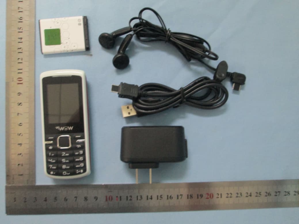
Click to zoom
Application Details
- Equipment Class
- PCE - PCS Licensed Transmitter held to ear
- Date of Grant
- Nov 27, 2012
- Application Purpose
- Original Equipment
- Date of Application
- Nov 27, 2012
- Equipment Note
- Mobile Phone
- Frequency Range
- 1850.20000000 - 1909.80000000
- Company
- WOW Mobiles co
- Country
- United States
Documents & Files
Document Text
Text extracted from the exhibit documents filed with the FCC. Open a document above to read the original.
Users Manual
Mobile Phone Model : W3520 Brand : WOW Mobiles FCC ID:ZBPW3520 User's Manual 1 General Information 1.1 Safety warning and Attentions Safety warning ¾ ROAD SAFETY COMES FIRST Do not use a hand-held phone while driving. Use hands-free fittings when calls are unavoidable while driving. In some countries, dialing or receiving calls while driving is illegal! ¾ SWITCH OFF IN AIRCRAFT Wireless devices can cause interference in aircraft. Using a mobile phone in flight is illegal and risky. Please make sure that your mobile phone is powered off in flight. ¾ SWITCH OFF BEFORE ENTERING RISKY AREAS Strictly observe the relevant laws, codes, and regulations on the use of mobile phones in risky areas. Turn off your mobile phone before entering a place susceptible to explosion, such as an oil station, oil tank, chemical plant or a place where a blasting process is under way. ¾ OBSERVE ALL SPECIAL REGULATIONS Follow any special regulations in force in any area such as hospitals and always switch off your phone whenever it is forbidden to use it or, when it may cause interference or danger. Properly use your mobile phone near medical apparatuses, such as pacemakers, hearing aids and some other electronic medical devices, as it may cause interference to such apparatuses. ¾ INTERFERENCE The conversation quality of any mobile phone may be affected by radio interference. An antenna is built inside the mobile phone and located below the microphone. Do not touch the antenna area during a conversation, lest that the conversation quality deteriorate. ¾ QUALIFIED SERVICE Only qualified personnel may install or repair phone equipment. Installing or repairing the mobile phone on your own may bring great danger and violates the warranty rules. ¾ ACCESSORIES AND BATTERIES Use only approved accessories and batteries. ¾ USE SENSIBLY Use only in a normal and proper manner. ¾ EMERGENCY CALLS Ensure the phone is switched on and in service, enter the emergency number, e.g. 112, then press the Dial key. Give your location and state your situation briefly. Do not end the call until told to do so. Note: Just like all other mobile phones, this mobile phone does not necessarily support all the features described in this manual due to network or radio transmission problems. Some networks even do not support the emergency call service. Therefore, do not rely solely on the mobile phone for critical communications such as first aid. Please consult the local network operator. Precautions This mobile phone is well designed with fine art. Please exercise special care when using it. The following suggestions will help your mobile phone survive the warranty period and extend its service life: ¾ Keep the mobile phone and all its fittings beyond children's reach. ¾ Keep the mobile phone dry. Keep away from rain, moisture, liquid or other substances that may corrode electronic circuits. ¾ Do not use or store the mobile phone in dusty places, lest that active parts of the mobile phone be damaged. ¾ Do not store the mobile phone in a high-temperature place. High temperature will shorten the life of electronic circuits and damage the battery and some plastic parts. ¾ Do not store the mobile phone in a chilly place. Otherwise, moistures will be formed inside the mobile phone to damage electronic circuits when the mobile phone is moved to a constant temperature place. ¾ Do not throw, knock or shock the mobile phone, as that will destroy the internal circuits and high-precision components of the mobile phone. 2 Your phone 2.1 Phone overview 2.2 Functions of Keys The mobile phone provides the following keys: Dial key(2) Press it to originate a call by entering the called number or selecting a contact from the phonebook; or press it to receive an incoming call; or press it in standby state to show the latest call records End key Press it to end a call being dialed or end an ongoing call; or press it to exit the menu and return to the standby state; or hold it for two or three seconds to power on or off the mobile phone. Direction key Press them to scroll the options when browsing function list. In standby state, press a direction key to enter the specified function page. You can also customize direction keys to match the desired functions. In conversation status, press up or down direction key to tune volume. OK key Press it to confirm your selection. In standby interface, pressing it will enter the main menu. Long press this key in the idle screen to turn on /turn off the torch at the top of the phone. Left and right soft key In the standby interface, press left soft key to add new contact, press right direction key to enter main menu. Number keys, * key and # key Press number keys 0 through 9 in edit state to input numbers and characters; hold any of number keys 2 through 9 for over two seconds in standby state to fast dial the corresponding telephone number in the speed-dial number list (need to set in advance). Note: Holding number key 1 on standby will call the voice mailbox service center. The voice mailbox center number, however, must be preset. The # key and the * key represent different functions in different states or different function menus. Hold the # key up to 2s in standby state to activate or deactivate the mute mode. Press the # key in edit state to switch between input methods, or press it to unlock the keyboard when the keyboard is locked. Pressing the * key in edit status to select a symbol. Press and hold the * key up for 2s to input "+" in standby interface. "+" are used for dialing an international call. 2.3 Technical specifications Size: 110*46.5*15.5mm Display: 1.77 inch QCIF Camera: High-definition Camera Battery: 650mAh Features: Memory: Support T-flash Card 3 Getting started 3.1 Installing the SIM Cards and the Battery An SIM card carries useful information, including your mobile phone number, PIN (Personal Identification Number), PIN2, PUK (PIN Unlocking Key), PUK2 (PIN2 Unlocking Key), IMSI (International …
Text truncated - open the document above for the full version.
Cover Letter(s)
Nov.23, 2012 Federal Communication Commission Authorization and Evaluation Division FCC ID: ZBPW3520 Re: Confidentiality Request Pursuant to Sections 0.457 and 0.459 of the Commission’s Rules, the applicant hereby requests confidential treatment of information applied this application as outlined below: 1: Block Diagram 2: Circuit Diagram 3: Operational Description 4: Parts List 5: Tune Up Procedure The above materials contain trade secrets and proprietary information not customarily released to the public. The public disclosure of these matters might be harmful to the applicant and provide unjustified benefits to its competitors. The Applicant understands that pursuant to Rules 0.457, disclosure of this Application and all accompanying documentation will not be made before the date of the Grant for this application. Sincerely yours, WOW Mobiles co Contact person: Hernan Descalzi Title: Product Manager
Cover Letter(s)
WOW Mobiles co 5694 Mission Center, Rd., Suite 602-362, San Diego, CA 92108, USA PHOENIX TEST-LAB GmbH Product Certification Königswinkel 10 D 32825 Blomberg Date: Nov.23,2012 FCC ID: ZBPW3520 Subject: Attestation Letter “Declaration of Conformity” Dear Sirs, Our products with the above FCC ID: ZBPW3520 are defined as composite device. The transmitter is authorized under the “Certification” procedure. The device is also defined as “PC Periphery” acc to §15.101 Equipment authorization of unintentional radiators, where we hereby declare, that we apply and follow the “FCC Declaration of Conformity” procedure, based on testing from a FCC accredited testing laboratory or involvement of a CB. And we will settle the JBP parts with DOC. If you have any questions, please feel free to contact me at the address shown below. Yours sincerely, WOW Mobiles co Contact person: Hernan Descalzi Title: Product Manager
Cover Letter(s)
WOW Mobiles co 5694 Mission Center, Rd., Suite 602‐362, San Diego, CA 92108, USA Date: Nov.23, 2012 Statement We, WOW Mobiles co states that our device, FCC ID: ZBPW3520, has no space to put the label except the battery compartment of this device. It is visible to the users as they purchase the products and install the battery. Sincerely yours, WOW Mobiles co Contact person: Hernan Descalzi Title: Product Manager
External Photos
TOP VIEW OF EUT BOTTOM VIEW OF EUT FRONT VIEW OF EUT BACK VIEW OF EUT LEFT VIEW OF EUT RIGHT VIEW OF EUT ALL VIEW OF SAMPLE
ID Label/Location Info
FCC ID Label Location Mobile Phone Model:W3520 WOW Mobiles FCC ID: ZBPW3520
Internal Photos
OPEN VIEW OF EUT-1 OPEN VIEW OF EUT-2 GSM Antenna OPEN VIEW OF EUT-3 INTERNAL VIEW OF EUT-1 BT Antenna INTERNAL VIEW OF EUT-2
RF Exposure Info
SAR Test Report Report No.: AGCY0Q121101S1 FCC ID : ZBPW3520 PRODUCT DESIGNATION : Mobile Phone BRAND NAME : WOW Mobiles MODEL NAME : W3520 CLIENT : WOW Mobiles co DATE OF ISSUE : Nov.21,2012 STANDARD(S) : FCC Oet65 Supplement C June 2001 IEEE Std. 1528‐2003,47CFR § 2.1093 REPORT VERSION : V1.0 Attestation of Global Compliance(Shenzhen) Co., Ltd. CAUTION: This report shall not be reproduced except in full without the written permission of the test laboratory and shall not be quoted out of context. Applica Applica Manufa Manufa Product Brand N Model N Differen EUT Vo Applica Te s t Da Te s t Re Perform nt Name nt Address cturer Name cturer Addre t Designatio Name Name nt Descriptio oltage ble Standard ate esults med Location Tes W 56 e C ess 4 7 C n M W W on N/ D d FC IE N M H ( S n At 2 G Documen Checke Authoriz st Rep WOW Mobile 694 Mission hina Electro 7 F, Block C hina Mobile Phone WOW Mobile W3520 /A C3.7V by ba CC Oet65 S EEE Std. 152 ov.19,2012 MAX SAR ME ead:1.213 W Scaling SAR ttestation of F, Building 2 ushu, Xixian nted By ed By zed By port C es co Center, Rd onics Shenzh C, Electronics e es attery Supplement 28-2003,47C EASUREME W/Kg Bod R=1.233 W/K fGlobal Com 2, No.1-No.4 ng Street, B Vivi Ze Angela Solger Z Certific ., Suite 602- hen Compa s Science & C June 200 CFR § 2.1 ENT(1g) dy:0.739W/K Kg) mpliance(Sh 4, Chaxi San ao'an Distric eng a Li hang Repo cation -362, San D ny & Technology 1 093 Kg enzhen) Co nwei Techni ct, Shenzhe Nov.21,201 Nov.21,201 Nov.21,201 ort No.: AG n Diego, CA 92 y Building, S o., Ltd. cal Industria n, China 2 2 2 GCY0Q12110 Page 1 of 2108, USA Shenzhen, al Park, 01S1 f 111 Report No.: AGCY0Q121101S1 Page 2 of 111 TABLE OF CONTENTS 1. GENERAL INFORMATION ............................................................................................................................ 3 1.1. EUT DESCRIPTION ...................................................................................................................................... 3 1.2. TEST PROCEDURE ...................................................................................................................................... 5 1.3. TEST ENVIRONMENT .................................................................................................................................... 5 2. SAR MEASUREMENT SYSTEM ..................................................................................................................... 6 2.1. COMOSAR SYSTEM DESCRIPTION .............................................................................................................. 6 2.2. COMOSAR E-FIELD PROBE ....................................................................................................................... 8 2.3. ROBOT ....................................................................................................................................................... 8 2.4. VIDEO POSITIONING SYSTEM ....................................................................................................................... 9 2.5. DEVICE HOLDER ......................................................................................................................................... 9 2.6. SAM TWIN PHANTOM ................................................................................................................................ 10 3. TISSUE SIMULATING LIQUID ..................................................................................................................... 11 3.1. THE COMPOSITION OF THE TISSUE SIMULATING LIQUID .................................................................................... 11 3.2. TISSUE CALIBRATION RESULT ..................................................................................................................... 12 3.3. TISSUE DIELECTRIC PARAMETERS FOR HEAD AND BODY PHANTOMS .............................................................. 13 4. SAR MEASUREMENT PROCEDURE ......................................................................................................... 14 4.1. SAR SYSTEM VALIDATION .......................................................................................................................... 14 4.2. SAR MEASUREMENT PROCEDURE ............................................................................................................. 16 5. SAR EXPOSURE LIMITS ............................................................................................................................ 17 6. TEST EQUIPMENT LIST ............................................................................................................................. 18 7. MEASUREMENT UNCERTAINTY ................................................................................................................ 19 8. CONDUCTED POWER MEASUREMENT .................................................................................................... 20 9. TEST RESULTS .......................................................................................................................................... 21 9.1. SAR TEST RESULTS SUMMARY .................................................................................................................. 21 APPENDIX A. SAR SYSTEM VALIDATION DATA .......................................................................................... 26 APPENDIX B. SAR MEASUREMENT DATA.................................................................................................... 30 APPENDIX C. TEST SETUP PHOTOGRAPHS &EUT PHOTOGRAPS ........................................................... 74 APPENDIX D. PROBE CALIBRATION DATA ................................................................................................. 85 APPENDIX E. DIPOLE CALIBRATION DATA ................................................................................................. 94 Report No.: AGCY0Q121101S1 Page 3 of 111 1. General Informati…
Text truncated - open the document above for the full version.
RF Exposure Info
Report No.: AGCY0Q121101S1 Page 74 of 111 Appendix C. TEST SETUP PHOTOGRAPHS &EUT PHOTOGRAPS Test Setup Photographs LEFT-CHECK TOUCH LEFT-TILT 15 0 Report No.: AGCY0Q121101S1 Page 75 of 111 RIGHT-CHECK TOUCH RIGHT-TILT 15 0 Report No.: AGCY0Q121101S1 Page 76 of 111 Body Back15mm Body Front15mm 1.5cm Report No.: AGCY0Q121101S1 Page 77 of 111 Body back with Headset Report No.: AGCY0Q121101S1 Page 78 of 111 DEPTH OF THE LIQUID IN THE PHANTOM—ZOOM IN Note:The position used in the measurement were according to IEEE 1528-2003 Report No.: AGCY0Q121101S1 Page 79 of 111 EUT PHOTOGRAPS TOP VIEW OF EUT BOTTOM VIEW OF EUT Report No.: AGCY0Q121101S1 Page 80 of 111 FRONT VIEW OF EUT BACK VIEW OF EUT Report No.: AGCY0Q121101S1 Page 81 of 111 LEFT VIEW OF EUT RIGHT VIEW OF EUT Report No.: AGCY0Q121101S1 Page 82 of 111 OPEN VIEW OF EUT-1 OPEN VIEW OF EUT-2 GSM Antenna Report No.: AGCY0Q121101S1 Page 83 of 111 OPEN VIEW OF EUT-3 INTERNAL VIEW OF EUT-1 BT Antenna Report No.: AGCY0Q121101S1 Page 84 of 111 INTERNAL VIEW OF EUT-2 Report No.: AGCY0Q121101S1 Page 85 of 111 Appendix D. Probe Calibration Data Report No.: AGCY0Q121101S1 Page 86 of 111 Report No.: AGCY0Q121101S1 Page 87 of 111 Report No.: AGCY0Q121101S1 Page 88 of 111 Report No.: AGCY0Q121101S1 Page 89 of 111 Report No.: AGCY0Q121101S1 Page 90 of 111 Report No.: AGCY0Q121101S1 Page 91 of 111 Report No.: AGCY0Q121101S1 Page 92 of 111 Report No.: AGCY0Q121101S1 Page 93 of 111 Report No.: AGCY0Q121101S1 Page 94 of 111 Appendix E. Dipole Calibration Data Report No.: AGCY0Q121101S1 Page 95 of 111 Report No.: AGCY0Q121101S1 Page 96 of 111 Report No.: AGCY0Q121101S1 Page 97 of 111 Report No.: AGCY0Q121101S1 Page 98 of 111 Report No.: AGCY0Q121101S1 Page 99 of 111 Report No.: AGCY0Q121101S1 Page 100 of 111 Report No.: AGCY0Q121101S1 Page 101 of 111 Report No.: AGCY0Q121101S1 Page 102 of 111 Report No.: AGCY0Q121101S1 Page 103 of 111 Report No.: AGCY0Q121101S1 Page 104 of 111 Report No.: AGCY0Q121101S1 Page 105 of 111 Report No.: AGCY0Q121101S1 Page 106 of 111 Report No.: AGCY0Q121101S1 Page 107 of 111 Report No.: AGCY0Q121101S1 Page 108 of 111 Report No.: AGCY0Q121101S1 Page 109 of 111 Report No.: AGCY0Q121101S1 Page 110 of 111 Report No.: AGCY0Q121101S1 Page 111 of 111
Test Report
FCC Test Report Report No.: AGCY0Q121101F2A FCC ID : ZBPW3520 PRODUCT DESIGNATION : Mobile Phone BRAND NAME : WOW Mobiles MODEL NAME : W3520 CLIENT : WOW Mobiles co DATE OF ISSUE : Nov.21, 2012 STANDARD(S) : FCC Part 22H & 24E Rules REPORT VERSION : V1.0 Attestation of Global Compliance (Shenzhen) Co., Ltd. CAUTION: This report shall not be reproduced except in full without the written permission of the test laboratory and shall not be quoted out of context. Report No.: AGCY0Q121101F2A Page 1 of 51 VERIFICATION OF COMPLIANCE Applicant: WOW Mobiles co 5694 Mission Center, Rd., Suite 602-362, San Diego, CA 92108, USA Manufacturer: China Electronics Shenzhen Company 47 F., Block C, Electronics Science & Technology Building, Shenzhen, China Product Designation: Mobile Phone Brand name: WOW Mobiles Test Model: W3520 FCC ID: ZBPW3520 Report Number: AGCY0Q121101F2A Date of Test: Nov.15, 2012 to Nov.21, 2012 We hereby certify that: The above equipment was tested by Attestation of Global Compliance (Shenzhen) Co., Ltd. The data evaluation, test procedures, and equipment configurations shown in this report were made in accordance with the procedures given in ANSI C 63.4:2003 and TIA/EIA 603. The sample tested as described in this report is in compliance with the FCC Rules Part 22H and 24E. The test results of this report relate only to the tested sample identified in this report. Tested By : Bart Xie Nov.21, 2012 Reviewed By : Forrest Lei Nov.21, 2012 Approved By: Solger Zhang Nov.21, 2012 Report No.: AGCY0Q121101F2A Page 2 of 51 TABLE OF CONTENTS 1. GENERAL INFORMATION ............................................................................................................................ 4 1.1 PRODUCT DESCRIPTION ........................................................................................................................... 4 1.2 RELATED SUBMITTAL(S) / GRANT (S) ....................................................................................................... 4 1.3 TEST METHODOLOGY ............................................................................................................................... 5 1.4 TEST FACILITY ............................................................................................................................................ 5 1.5 MEASUREMENT INSTRUMENTS ............................................................................................................... 5 1.6 SPECIAL ACCESSORIES ............................................................................................................................ 5 1.7 EQUIPMENT MODIFICATIONS ................................................................................................................... 5 2. SYSTEM TEST CONFIGURATION ............................................................................................................... 6 2.1 EUT CONFIGURATION ................................................................................................................................ 6 2.2 EUT EXERCISE ........................................................................................................................................... 6 2.3 GENERAL TECHNICAL REQUIREMENTS ................................................................................................. 6 2.4 CONFIGURATION OF EUT SYSTEM ......................................................................................................... 6 3. SUMMARY OF TEST RESULTS ................................................................................................................... 7 4. DESCRIPTION OF TEST MODES ................................................................................................................. 7 5. OUTPUT POWER .......................................................................................................................................... 8 5.1 CONDUCTED OUTPUT POWER ................................................................................................................ 8 5.2 RADIATED OUTPUT POWER ................................................................................................................... 10 6. PEAK-TO-AVERAGE RATIO ....................................................................................................................... 12 7. SPURIOUS EMISSION ................................................................................................................................ 13 7.1 CONDUCTED SPURIOUS EMISSION ...................................................................................................... 13 7.2 RADIATED SPURIOUS EMISSION ........................................................................................................... 15 8. MAINS CONDUCTED EMISSION ............................................................................................................... 19 8.1 MEASUREMENT METHOD ....................................................................................................................... 19 8.2 PROVISIONS APPLICABLE ...................................................................................................................... 19 Report No.: AGCY0Q121101F2A Page 3 of 51 8.3 MEASUREMENT RESULT ......................................................................................................................... 20 9. FREQUENCY STABILITY ............................................................................................................................ 22 9.1 MEASUREMENT METHOD ....................................................................................................................... 22 9.2 PROVISIONS APPLICABLE ...................................................................................................................... 22 9.3 MEASUREMENT RESULT .......................................................................................................…
Text truncated - open the document above for the full version.
Test Setup Photos
CONDUCTED EMISSION RADIATED SPURIOUS EMISSION
Contact Information
Applicant
Hernan Descalzi(Product Manager)
Test Firm
Attestation of Global Compliance Shenzhen Co. Ltd.Forrest Lei
Technical Specifications
| # | Rule Parts | Frequency Range | Power Output | Emission | Tolerance |
|---|---|---|---|---|---|
| 2 | 24E | 1.85 GHz - 1.91 GHz | 700.00 mW | 247KGXW | 0.03 ppm |