ZCJTPKVSASRF1car alarm system receiver module
Shenzhen Tongyijia Industrial Develop Co., Ltd.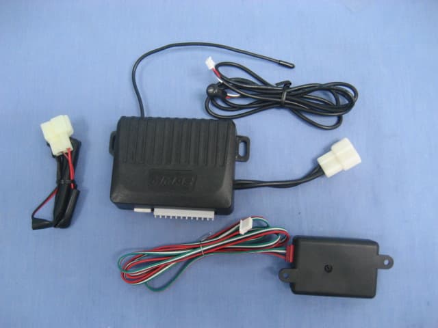
Click to zoom
Application Details
- Equipment Class
- CRR - Superregenerative Receiver
- Date of Grant
- Mar 17, 2011
- Application Purpose
- Original Equipment
- Date of Application
- Mar 17, 2011
- Equipment Note
- car alarm system receiver module
- Frequency Range
- 433.92000000 - 433.92000000
- Country
- China
Documents & Files
Document Text
Text extracted from the exhibit documents filed with the FCC. Open a document above to read the original.
Users Manual
ARMINGTHESECURITYSYSTEM REMOTECONTROLARMING 1.Exitthevehicleandcloseallentrypoints. 2.Press“BUTTONI”ontheremotecontroltransmitter. Thesirenwillchirptwo(2)timesandtheparkinglightswillflashtwo(2) timesindicatingthatthesystemisarmed. AUTOMATICARMING Ifthesystemisnotarmedmanually,thesystemwillarmautomaticallywhen: 1.Ignitionkeyisturnedoff. 2.Anydoorisopenedthenclosed. 3.Oneminutehaselapsedafteralldoorsareclosed. “IF“thesirenonlychirpsonetimewhenarmingthesystem,check thestatusindicator. •Ifthestatusindicatorison“RED/GREEN“,adoor,trunkorhatchis open.Thesystemwillarmafter DISARMINGTHESECURITYSYSTEM Press“BUTTONII“ontheremotecontroltransmitter.Thesirenwillemit one(1)chirpandtheparkinglightswillflashonetimetoindicatethe systemisdisarmed.Ifthesirensoundsfour(4)shortchirps,thealarmhas soundedwhileyouwereaway.Thesystemwillrearminoneminuteunless theignitionisturnedonorthesystemisplacedinthevaletmode. REMOTECONTROLPANICALARM Whenactivated,panicalarmwillsoundthesirencontinuouslyandflash theparkinglightsfor30seconds.Toactivatethepanicalarm,“Press BUTTONIandIIatthesametimeorpressBUTTONIV“ontheremote controltransmitter.ThepanicalarmcanbeshutoffbypressingBUTTTON IIontheremotecontroltransmitter,thenpressBUTTONItoarmthe systemagain. Valetmodepreventsthesecuritysystemfrombeingarmed.Onlythelock 2 ARMINGTHESECURITYSYSTEM andunlockfeaturewillfunction.Valetmodeisusefulwhenvaletparking, fuellingorservicingyourvehicle. Toactivatethevaletmode: 1.Turntheignitiontothe“ON“position. 2.Togglethevaletswitch“ON“. 3.Thestatusindicatorwilldisplaya“SOLIDRED“confirmingthatthe systemisinthevaletmode. 4.Turntheignition“OFF“. Tore-enterthenormaloperatingmode: 1.Turntheignitiontothe“ON“position. 2.Togglethevaletswitch“OFF“. 3.Thestatusindicatorwillbe“OFF“. 4.Turntheignition“OFF“. Note:Valetswitchislocatedunderdash,leftpanelbesidethehood release. DISARMINGTHESYSTEMWITHOUTTHEREMOTECONTROL TRANSMITTER 1.Iftransmitterislostornotfunctioning. 2.Openthedriver’sdoor(alarmwillbeginsoundingassoonasthedooris opened). 3.Turntheignitionkeytothe“ON“position. 4.Togglethevaletswitchtothe“ON“position. 5.Thesecuritysystemisnowdisarmed. 3 VISUALALARMSTATUSINDICATOR Thevisualalarmstatusindicatorisahighintensityredblinkinglight.The statusindicator,mountedinalocationvisiblefromtheoutsideofthe vehicle,displaysthesecuritysystem’sstatuswhilecreatingapowerful theftdeterrent.Thechartonthispageshowsthedifferentstatus indicationsandtheirmeanings. VALET MODE •Ifthestatusindicatorison“SOLID RED“,the system is in the valet mode. that opening is closed. The system will arm after the valet mode is disengaged.
Users Manual
ARMINGTHESECURITYSYSTEM 45 SECURITYFEATURES HOWTHESECURITYSYSTEMPROTECTSYOURVEHICLE? Whenthesecuritysystemisarmed: 1.Thevisualstatusindicatorflashesoncepersecondtocreateapowerful theftdeterrent. 2.Theenginewillnotstart.Thesecuritysystem’s“starterinterrupt“ electronicallydisablesthestartermotor. 3.Allprotectedentrypointsandsensorinputsarecontinuallymonitored. Whenthealarmissoundingthefollowingeventsoccur: •Visualstatusindicatorbeginsflashingrapidly. •Sirensoundscontinuously. •Vehiclesparkinglightsflashoncepersecond. Thealarmwillsoundfor30secondsandthenshutdownreturningthe securitysystemtoafullyarmedstate,exceptwhentheviolatedentry pointsisleftopen.Inthiscase,thealarmwillshutdownfor10seconds andthenresumesoundingtoattractmoreattention.Thecyclerepeats untiltheviolatedentrypointsisclosed. SHOCKSENSOR Theshocksensorisdesignedtodetectimpactstothebodyofthevehicle. Theforceofimpact(orthreshold)requiredto“trip”theshocksensitivity sensorisfullyadjustable.Ithasanadjustertosetthedesiredlevelof SECURITYFEATURES sensitivity.Whenthesystemisarmed,theshocksensorcontinually monitorsforimpacttothebodyofthevehicle. LITE-TOUCH Whentheshocksensesanon-threateningimpacttothebodyof vehicle,thesirenwillsoundashort“Lite-touch”Chirptowarnawaya potentialintruder. SHOCKSENSOROVERRIDE Insomecasesitmaybedesirabletooverridetheshocksensorportionof thesecuritysystemtemporarily. Here’show: 1.Press“BUTTONI“oftheremotecontroltransmitter. 2.Withinthree(3)secondsofthesecondarmingchirps,pressBUTTONI again. Thesystemwillrespondwiththree(3)shortsirenchirps,indicatingthe shocksensorisdisabled. Tore-entertheshocksensorpressBUTTONIIontheremotecontrol transmitter,thenpressBUTTONI.Thesirenwillchirpstwo(2)timesand parkinglightswilltwo(2)times. ARMINGTHESYSTEMWHENAPROTECTEDENTRYPOINTISOPEN Whenthereisaprotectedentrypointopenatthetimethatthesystem attemptstoarm,thesirenwillchirpandtheparkinglightswillflashone time.Thesystemwillthenwait,inapre-armedstate,untiltheprotected entrypointisclosed.Whileinpre-armthestatusindicatorwillbeon red/greenlightflashing,indicatingthesystemiswaitingtoarm.Afterthe entrypointhasbeenclosed,thesirenwillchirpandtheparkinglightswill flashagain,thistimeindicatingthatthesystemisarmed. AUTOMATICDOORLOCKANDUNLOCK Ifallprotectedopeningsareclosedwhentheignitionkeyisturnedtothe onposition,thesecuritysystemwilllockthedoors.Whenthekeyisturned STATUSINDICATORSYSTEMSTATUS TRIGGERMEMORYINDICATOR OFFDISARMED RED/GREENARMED STATUSINDICATORSYSTEMSTATUS FLASHINGGREEN /RED/GREEN/RED DOORTRIGGERED SOLIDREDVALETMODE FLASHINGGREEN /GREEN/RED/RED TRUNKTRGGERED RAPIDFLASH FLASHINGGREEN /RED/RED/GREEN PASSIVEARMING COUNTDOWN SHOCKSENSOR TRIGGERED
Users Manual
SECURITYFEATURES backoff,thesystemwillunlockthedoorstoallowaneasyexitfromthe vehicle.Ifdesired,eitheroneorbothofthesefeaturescanbeturnedoffby yourinstaller. 67 SECURITYFEATURES PROGRAMMING 1.TurnignitionON. 2.Togglevaletswitch3timesON/OFF.Sirenwillchirp2times. 3.PressBUTTON1. 4.Sirenwillchirp2times. 5.TogglevaletswitchOFF 6.TurnignitionOFF OTHERUSEFULINFORMATION LOWVEHICLEBATTERY? Shouldyoueverexperienceasituationwhere: •Thestarterwillnotengageafterthealarmhasbeendisarmed. •Thestarterengagesandthenalmostimmediatelydisengages. Theseconditionsarealmostalwayscausedbyaweekordefectivevehicle battery.“IF“thishappen,TOGGLETHEVALETSWITCHONWHILE TURNINGTHEIGNITIONKEYTOTHESTARTPOSITION.Thiswillbypass thestarterinterruptinthesystemcontrolmodule.Shouldthissituation continuetooccur,haveyourvehiclebatteryandstartingsystemcheckedout byyourmechanic. SYSTEMMAINTENANCE Yoursecuritydoesnotrequireanyspecificmaintenanceexceptfor occasionallychangingtransmitterbatteries.However,itissuggestedthat thesystembearmedandallprotectedzonesshouldbecheckedon OTHERUSEFULINFORMATION regularbasistomakesurethattheytriggeranalarmcycle.Shouldthe systemmalfunctioninanyway,contactyourdealerassoonaspossible forservice. ABOUTTRANSMITTERRANGE.... Thereceiverinsideyourvehiclesecuritysystemandtheremotecontrol transmitteraredesignedtogethertohaveaneffectiveoperatingrangeof upto50feetduringnormalconditions.Althoughattimesyouwill experiencerangegreaterthanthat,therearecertainconditionsthatwill causetheeffectivetransmitterrangetobelessthanyouwouldnormally experience.Atmosphericconditionsandradiointerferencearejustafew exampleofthetypesofinterferencethatcanreducetransmitterrange. ThisdevicecomplieswithFCCrulespart15.Operationissubjecttothe followingtwoconditions:(1)thisdevicemaycauseharmfulinterference and(2)thisdevicemustacceptanyinterferencethatmaycause undesiredoperation.Changesormodificationsnotexpresslyapprovedby thepartyresponsibleforcompliancecouldvoidtheuser’sauthorityto operatetheequipment.
Cover Letter(s)
Ersteller: U. Rodemeier Revision: 04 Erstelldatum: 03.08.01 Datum: 11.05.07 Seite 1 von 1 Request for Confidentiality PHOENIX TESTLAB GmbH Date: 2011-03-14 Product Certification Königswinkel 10 D 32825 Blomberg RE: Certification Application FCC ID: ZCJTPKVSASRF1 Confidentiality Request Pursuant to Sections 0.457 and 0.459 of the Commission’s Rule, the applicant hereby requests confidential treatment of information accompanying this application as outlined below: • BOM • Operation Description • Schematics • Block Diagram (XXXXX to be replaced by Schematics, Block Diagram, etc.) The above materials contain trade secrets and proprietary information not customarily released to the public. The public disclosure of these matters might be harmful to the applicant and provide unjustified benefits to its competitors. The applicant understands that pursuant to rule 0.457, disclosure of this application and all accompanying documentation will not be made before the date of the GRANT for this application. Thank you for your attention in this matter. Applicant’s Company: Centre Testing International Corporation address : Bldg. C, Hongwei Industrial Park, Block 70, Bao’an District, Shenzhen, Guangdong, China Signature : Job Title and Dept. :EMC Engineer, EMC Lab
ID Label/Location Info
FCC label information: M/N: V500 MMAS FCC ID: ZCJTPKVSASRF1 This device can be expected to comply with part 15 of the FCC Rules provided it is assembled in exact accordance with the instructions provided with this kit. Operation is subject to the following conditions: (1)This device may not cause harmful interference, and (2) this device must accept any interference received including interference that may cause undesired operation. Label
Test Report
Report No. : EESZD03030005-2 Page 1 of 13 FCC TEST REPORT Product Name : car alarm system receiver module Trade Name : avt Model Name : V500 MMAS FCC ID : ZCJTPKVSASRF1 Serial Number : N/A Technical Data : DC 9~18V Report Number : EESZD03030005-2 Date : Mar. 14, 2011 Regulations : See below Test Standards Results FCC Part 15 Subpart B: 2009 PASS Prepared for: Shenzhen Tongyijia Industrial Develop Co., Ltd. 11/L, HANGDU BUILDING, NO.1006 HUAFU ROAD, SHENZHEN, CHINA Prepared by: CENTRE TESTING INTERNATIONAL (SHENZHEN) CORPORATION Building C, Hongwei Industrial Zone, Baoan 70 District, Shenzhen, Guangdong, China TEL: +86-755-3368 3362 FAX: +86-755-3368 3385 Check No.: 57126532 This report shall not be reproduced, except in full, without the written approval of CENTRE TESTING INTERNATIONAL (SHENZHEN) CORPORATION Report No. : EESZD03030005-2 Page 2 of 13 TABLE OF CONTENTS Description Page 1. GENERAL INFORMATION ..........................................................................................3 2. TEST SUMMARY .........................................................................................................4 3. MEASUREMENT UNCERTAINTY ...............................................................................4 4. PRODUCT INFORMATION AND TEST SETUP ..........................................................4 5. FACILITIES AND ACCREDITATIONS .........................................................................5 6. RADIATED EMISSION TEST.......................................................................................6 APPENDIX 1 PHOTOGRAPHS OF TEST SETUP............................................................10 APPENDIX 2 PHOTOGRAPHS OF EUT ..........................................................................11 (Note: N/A means not applicable) Report No. : EESZD03030005-2 Page 3 of 13 1. GENERAL INFORMATION Applicant: Shenzhen Tongyijia Industrial Develop Co., Ltd. 11/L, HANGDU BUILDING, NO.1006 HUAFU ROAD, SHENZHEN, CHINA Manufacturer: Shenzhen Tongyijia Industrial Develop Co., Ltd. 11/L, HANGDU BUILDING, NO.1006 HUAFU ROAD, SHENZHEN, CHINA Equipment Authorization: Certification Product Name: car alarm system receiver module Trade Name: avt Model Name: V500 MMAS Serial Number: N/A Report Number: EESZD03030005-2 Date of Test: Mar. 03, 2011 to Mar. 14, 2011 The results of this test report are only valid for the mentioned equipment under test. The test report with all its sub-reports, e.g. tables, photographs and drawings, is copyrighted. Unauthorized utilization, especially without permission of the test laboratory, is not allowed and punishable. For copying parts of the test report, a written permission by the test laboratory is needed. The test results of this report relate only to the tested sample identified in this report. Prepared by : Christy Chen Reviewed by : Louisa Lu Approved by : Lily Yan Supervisor Date Mar. 14, 2011 Report No. : EESZD03030005-2 Page 4 of 13 2. TEST SUMMARY The EUT has been tested according to the following specifications: Standard Test Item Test FCC 15.107 Conducted Emission N/A* FCC 15.109 Radiated Emission Yes * The power supply of EUT is by DC. 3. MEASUREMENT UNCERTAINTY Where relevant, the following measurement uncertainty levels have been estimated for tests performed on the EUT as specified in CISPR 16-4-2. This uncertainty represents an expanded uncertainty expressed at approximately the 95% confidence level using a coverage factor of k=2. Test item Value (dB) Radiated Emission 4.4 4. PRODUCT INFORMATION AND TEST SETUP 4.1. PRODUCT INFORMATION Technical Data: DC 9~18V 4.2. TEST SETUP CONFIGURATION See test photographs attached in Appendix 1 for the actual connections between EUT and support equipment. 4.3. SUPPORT EQUIPMENT No. Device Type Brand Model Series No. Data Cable Power Cord 1. --- --- --- --- --- --- Notes: 1. All the equipment/cables were placed in the worst-case configuration to maximize the emission during the test. 2. Grounding was established in accordance with the manufacturer’s requirements and conditions for the intended use. Report No. : EESZD03030005-2 Page 5 of 13 5. FACILITIES AND ACCREDITATIONS 5.1. TEST FACILITY All test facilities used to collect the test data are located at Building C, Hongwei Industrial Zone, Baoan 70 District, Shenzhen, Guangdong, China. The site and apparatus are constructed in conformance with the requirements of ANSI C63.4, CISPR 16-1-1 and other equivalent standards. 5.2. TEST EQUIPMENT LIST Instrumentation: The following list contains equipments used at CTI for testing. The calibrations of the measuring instruments, including any accessories that may effect such calibration, are checked frequently to assure their accuracy. Adjustments are made and correction factors applied in accordance with instructions contained in the manual for the measuring instrument. Equipment used during the tests: 3M Semi-anechoic Chamber - Radiated Emission Test Equipment Manufacturer Model Serial No. Due Date 3M Chamber & Accessory Equipment ETS-LINDGRENFACT-3 3510 07/09/2012 Spectrum Analyzer Agilent E4440A MY46185649 04/09/2011 Biconilog Antenna ETS-LINGREN 3142C 00044562 07/31/2011 Horn Antenna ETS-LINGREN 3117 00057407 06/07/2011 Microwave Preamplifier Agilent 11909A 186871 N/A 5.3. LABORATORY ACCREDITATIONS AND LISTINGS The measuring equipment utilized to perform the tests documented in this report has been calibrated once a year or in accordance with the manufacturer's recommendations, and is traceable under the ISO/IEC/EN 17025 to international or national standards. Equipment has been calibrated by accredited calibration laboratories. Report No. : EESZD03030005-2 Page 6 of 13 6. RADIATED EMISSION TEST 6.1. LIMITS Limits for Class B digital devices Frequency (MHz) limits at 3m dB(μV/m) 30-88 40.0 88-216 43.5 216-960 46.0 Above 960 54.0 NOTE: 1. The lower limit shall apply at the transition frequency. 2. The limits shown above are based on measuring equipment employing a CISPR quasi-peak de…
Text truncated - open the document above for the full version.
Test Setup Photos
RADIATED EMISSION TEST SETUP
Contact Information
Applicant
Sixuan You
Test Firm
CENTRE TESTING INTERNATIONAL CORPORATIONChristy Chen
Technical Specifications
| # | Rule Parts | Frequency Range | Power Output |
|---|---|---|---|
| 1 | 15B | 433.92 MHz - 433.92 MHz | - |
Other Applications from Shenzhen Tongyijia Industrial Develop Co., Ltd.
ZCJT66T32T85
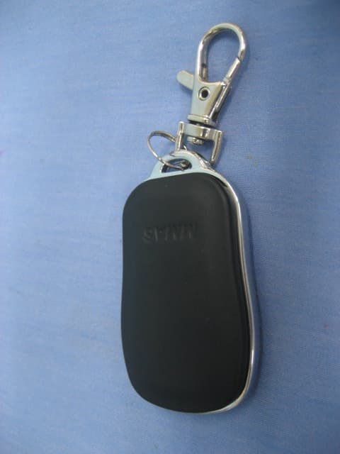
Mar 17, 2011car alram system remote control
Equipment Class
DSC - Part 15 Security/Remote Control Transmitter