ZEJCRReceiver
STOBAG North America Corporation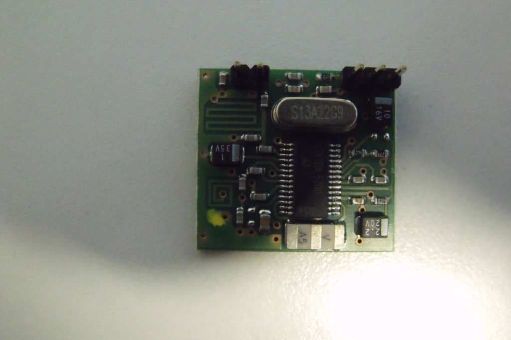
Click to zoom
Application Details
- Equipment Class
- CYY - Communications Receiver used w/Pt 15 Transmitter
- Date of Grant
- Nov 20, 2011
- Application Purpose
- Original Equipment
- Date of Application
- Nov 16, 2011
- Equipment Note
- Receiver
- Frequency Range
- 433.92000000 - 433.92000000
- Country
- Canada
Documents & Files
Document Text
Text extracted from the exhibit documents filed with the FCC. Open a document above to read the original.
Users Manual
SRCR 180 A SRCR 200 A Control unit www.stobag.com Schöne Schattenseiten. Stay cool in the shade. Anweisungen und Hinweise für den Installateur Instructions et recommandations pour l’installateur Istruzioni ed avvertenze per l’installatore Instructions and warnings for the fitter Instrucciones y advertencias para el instalador SRCR_180_A_200_A.indd 1SRCR_180_A_200_A.indd 122.2.2010 8:27:53 Uhr22.2.2010 8:27:53 Uhr Elektrische Anlagen und Automatisierungen müssen von erfahrenem und qualifi ziertem Personal unter Einhal- tung der gesetzlichen Vorschriften durchgeführt werden. Alle Anschlüsse müssen ohne Stromversorgung ausge- führt werden. Für die Installation und die Befestigung der Box, auf Abbildung 5 Bezug nehmen; um den Boden der Box zu befestigen, diesen an den dazu vorbereiteten Stellen lochen. Wenn der Boden der Box für die Durchführung der Kabel gelocht wird, sind entsprechende Mass- nahmen zu treffen, damit die erforderliche Schutzart IP gewährleistet bleibt. Die Kabel müssen mit geeigneten Kabeldurchführungen im- mer von unten her eingeführt werden. Die Steuerung SRCR 200 A kann 2 Motoren unabhängig sowie syn- chronisiert steuern: 1. Der synchronisierte Modus wird benutzt, wenn die 2 Motoren denselben Rollladen bewegen. In diesem Fall wird, nachdem Motor M1 den Endschalter erreicht hat und anhält, auch der Motor M2 an- gehalten. Für einen korrekten Betrieb dürfen nur die Endschalter von Motor M1 eingestellt werden, wogegen die Endschalter von Motor M2 auf den Höchstwert gestellt werden müssen, so dass sie nie ansprechen. 2. Den unabhängigen Modus benutzt man, wenn die 2 Motoren zwei Rollläden gesondert bewegen; in diesem Fall kann die Steuerung nur An- oder Abstiegsbewegungen gleichzeitig an beiden Motoren steuern, und die Endschalter sind an jedem Motor einzustellen. 5 Mit den Steuerungen SRCR 180 A und SRCR 200 A können ein- phasige, mit Netzspannung gespeiste Asynchronmotoren gesteuert werden, mit Anschlüssen wie “GEMEINSAM-AUF-AB”, die zur Au- tomatisierung von Markisen, Jalousien, Oberlichtern und ähnlichem verwendet werden. Mit der Steuerung SRCR 180 A kann nur ein Motor gesteuert werden, wogegen die SRCR 200 A zwei Motoren unabhängig (jeder Motor hält mit seinem Endschalter an) sowie syn- chronisiert (man benutzt den Endschalter des einen Motors und der zweite hält synchron mit dem ersten an) steuern kann. In die Steuerungen SRCR 180 A und SRCR 200 ist ein Funkempfän- ger eingebaut, der auf einer Frequenz von 433.92 MHz mit Rolling Code Technologie arbeitet und ein hohes Sicherheitsniveau gewähr- leistet. Für jede Steuerung können bis zu 30 Funksteuerungen der Serie “SRCH” (Abb. 1), “SRCW” (Abb. 2) oder Funksensoren “SKI- ROSOL SRCK 610” (Abb. 3). gespeichert werden. Nach jedem Befehl wird der Motor ca. 2,5 Minuten gespiesen: Ein elektrischer Endschalter im Motor oder in der Automatisierung un- terbricht die Bewegung, wenn die gewünschte Stellung erreicht ist. Die Programmierung von Zusatzfunktionen kann von den Sendern aus erfolgen, ein Biepton wird ihre verschiedenen Phasen signalisieren. Die Steuerungen SRCR 180 A und SRCR 200 A können mit zwei Tasten aktiviert werden, eine mit der Funktion Auf, die andere mit der Funktion Ab, oder per Bus (TTBUS). Als optional erhältliche Sensoren für Wind, Sonne und Regen können die Steuerungen automatisch schalten, wenn es die Witterung erfordert; die Einstellung der Aus- lösungsgrenzwerte von “Sonne” und “Wind” ist mit zwei Trimmern in der Steuerung möglich. 1) Relais Motor M1 “Ab”. 2) Relais Motor M1 “Auf”. 3) Relais Motor M2 “Ab” (nicht vorhanden an der SRCR 180 A). 4) Relais Motor M2 “Auf” (nicht vorhanden an der SRCR 180 A). 5) Relais zur Kontrolle der Versorgung von Motor M2 (nicht vorhan- den an der SRCR 180 A). 6) LED “WIND” Grenze. 7) LED “SONNE” Grenze. 8) Dip-switch für die Programmierung. 9) Trimmer zur Einstellung der “SONNE” Grenze. 10) Trimmer zur Einstellung der “WIND” Grenze. 11) Klemmenbrett für den Anschluss der Antenne. 12) Klemmenbrett für den Anschluss von Tasten und Sensoren. 13) Klemmenbrett für den Anschluss der Versorgung und der Motoren (Klemmen 5, 6, 7, 8; nicht vorhanden an der SRCR 180 A). 14) Sicherung: 6,3 A Typ T an SRCR 200 A, 5 A Typ F an SRCR 180 A. 2) Installation Hinweise Die Steuerungen SRCR 180 A und SRCR 200 A dienen zur Schaltung einphasiger, mit Netzspannung gespeister Asynchronmotoren, die zur Au- tomatisierung von Jalousien, Markisen und ähnlichem benutzt werden. Jeder andere Gebrauch ist unsachgemäss und verboten. Die Installation muss von technischem Personal unter voller Einhaltung der gültigen Vor- schriften durchgeführt werden. 1234567 8 9 10 11 1213 14 4 2 www.stobag.com 1) Beschreibung des Produktes 1 SKIMY SRCH 2 SKIMY SRCW 3 SKIROSOL SRCK 610 SRCR_180_A_200_A.indd 2SRCR_180_A_200_A.indd 222.2.2010 8:27:57 Uhr22.2.2010 8:27:57 Uhr 2.1.1) Anschluss der Motoren Der einphasige Asynchronmotor M1 muss zwischen den Klemmen 1-2-3-4 an der Netzspannung angeschlossen werden. AB entspricht der Taste ▼ an den Fernbedienungen, AUF der Taste ▲ an den Fern- bedienungen (Richtung infolge des Ansprechens des Windwächters). Sollte der Drehsinn nicht korrekt sein, die Verbindungen der Klemmen 1 und 3 austauschen. Der einphasige Asynchronmotor M2 muss zwi- schen den Klemmen 5-6-7-8 an der Netzspannung angeschlossen werden. Sollte der Drehsinn nicht korrekt sein, die Verbindungen der Klemmen 5 und 7 austauschen. Für den synchronisierten Modus müssen die Endschalter am Motor M1 eingestellt werden, an M2 werden die Endschalter nie benutzt und sind so einzustellen, dass sie nie ansprechen. An der Steuerung SRCR 200 A, im synchronisierten Mo- dus bzw. mit den zwei Motoren an den entgegengesetzten Seiten desselben Rollladens montiert, müssen die elek- trischen Anschlüsse so ausgeführt werden, dass die Dre- hung im gleichen Drehsinn erfolgt; dies erfolgt gewöhn- lich, wenn man die Anschlüsse von M2 im Vergleich zu jenen von M1 umkehrt. Im synchronisierten Modus kann nur ein Motor an jedem Ausgang angeschlos…
Text truncated - open the document above for the full version.
Block Diagram
STOBAG PAG. 5 di 28 Technical schemes SRCR 200A USA RL1 RL2 OPEN CLOSE Antenna IC1 AM Receiver X3 PLL Osc. 13.225 MHz IC3 Decoder & Control Unit 4 MHz Osc. CON 3 120 VAC MOTOR 1 120 VAC CON 3 C32, C33, C34 T1, D13-D14 IC4 TO IC1, IC2, IC3 DIP1 SWITC 3X CON2 sensors DL1 led BUZZER RL3 RL4 OPEN CLOSE CON 3 120 VAC MOTOR 2 STOBAG PAG. 6 di 28 SRCR 180A USA RL1 RL2 OPEN CLOSE Antenna IC1 AM Receiver X3 PLL Osc. 13.225 MHz IC3 Decoder & Control Unit 4 MHz Osc. CON 3 120 VAC MOTOR 1 120 VAC CON 3 C32, C33, C34 T1, D13-D14 IC4 TO IC1, IC2, IC3 DIP1 SWITC 3X CON2 sensors DL1 led BUZZER
ID Label/Location Info
November 16, 2011 RE: ATCB011139 – Original Equipment & Multiple Listing Certification Applications – Models: SRCR 200 A USA & SRCR 180 A USA FCC ID: ZEJCR & IC: 9590A-CR for STOBAG North America Corp. Our answers between the rows. 1. Please provide a photo or drawing showing the location of the FCC ID label upon the product. Section 2.1033(b)(7) of the FCC Rules requires a drawing showing the label location when a drawing of the label is provided instead of a photograph of the label on the device. I still cannot determine where the label is located from the drawings provided. I note that I have no photo of the bottom of the device so I cannot tell what the exterior of the bottom looks like. IMQ: ok, you can find the pictures of all product external side. The label is put into the internal side of the cover. 2. The following items must be corrected before the IC application form can be submitted to IC for listing of this device on the REL in Canada: (a) On page 1 of the application form, the telephone number and fax number for Rolf Jahn do not agree with information contained in the IC data base for Rolf Jahn. See attachment entitled “_IC Company (11139) 9590A Info.pdf.” Please correct these numbers on the IC application form or have the IC data base corrected. To have the IC data base corrected, please contact Ms. Marianne Bosley by email at [email protected]. IMQ: the customer declare that the right numbers are been issued in the application form. (b) The submitted Canadian representative letter has several problems with it. I suggest that you use STOBAG North America Corporation as the Canadian representative for this application. Just fill out the Canadian Representative information exactly as the applicant information at the top of this page. This is the easiest way to fix this problem. If STOBAG does not want to act as the Canadian rep for this device, please let me know. There are 8 other things that must be fixed to get this application going. IMQ: ok, please proceed with only STOBAG North America Corporation as the Canadian representative. (c) The receiver spurious worst case emission on page 2 of the form does not agree with the worst case emission level shown on page 15 of 25 in the submitted test report. An emission of 46.3 dBuV/m @ 3m is listed on this page that is higher than the level on the IC application form. Please address. IMQ: The test report 20811FCC11 shows a scan whole band from 30MHz to 2GHz without the use of preamplifiers and then scan follows the attenuation factor of antenna + cables, in any case under the limit. If we use a preamp would find lower values and the scale of the indicated value of <42dBuV / m I remain to your disposal for any clarification needed. Best regards Francesco Barbieri
Internal Photos
N N i i c c e e S S p p A A V V i i a a P P e e z z z z a a A A l l t t a a , , 1 1 3 3 Z Z . . I I . . R R u u s s t t i i g g n n è è I I - - 3 3 1 1 0 0 4 4 6 6 O O d d e e r r z z o o T T V V I I t t a a l l i i a a P P h h o o n n e e + + 3 3 9 9 . . 0 0 4 4 2 2 2 2 . . 8 8 5 5 3 3 8 8 3 3 8 8 F F a a x x + + 3 3 9 9 . . 0 0 4 4 2 2 2 2 . . 8 8 5 5 3 3 5 5 8 8 5 5 P P . . I I V V A A 0 0 3 3 0 0 9 9 9 9 3 3 6 6 0 0 2 2 6 6 9 9 i i n n f f o o @ @ n n i i c c e e f f o o r r y y o o u u . . c c o o m m w w w w w w . . n n i i c c e e f f o o r r y y o o u u . . c c o o m m Annex 1 Photo 1 - Same PCB TT5/V1 Nice and Stobag Photo 2 - Same PCB TT5/V1 Nice and Stobag N N i i c c e e S S p p A A V V i i a a P P e e z z z z a a A A l l t t a a , , 1 1 3 3 Z Z . . I I . . R R u u s s t t i i g g n n è è I I - - 3 3 1 1 0 0 4 4 6 6 O O d d e e r r z z o o T T V V I I t t a a l l i i a a P P h h o o n n e e + + 3 3 9 9 . . 0 0 4 4 2 2 2 2 . . 8 8 5 5 3 3 8 8 3 3 8 8 F F a a x x + + 3 3 9 9 . . 0 0 4 4 2 2 2 2 . . 8 8 5 5 3 3 5 5 8 8 5 5 P P . . I I V V A A 0 0 3 3 0 0 9 9 9 9 3 3 6 6 0 0 2 2 6 6 9 9 i i n n f f o o @ @ n n i i c c e e f f o o r r y y o o u u . . c c o o m m w w w w w w . . n n i i c c e e f f o o r r y y o o u u . . c c o o m m Photo 3 - Same PCB TT5/V1 for Nice and Stobag N N i i c c e e S S p p A A V V i i a a P P e e z z z z a a A A l l t t a a , , 1 1 3 3 Z Z . . I I . . R R u u s s t t i i g g n n è è I I - - 3 3 1 1 0 0 4 4 6 6 O O d d e e r r z z o o T T V V I I t t a a l l i i a a P P h h o o n n e e + + 3 3 9 9 . . 0 0 4 4 2 2 2 2 . . 8 8 5 5 3 3 8 8 3 3 8 8 F F a a x x + + 3 3 9 9 . . 0 0 4 4 2 2 2 2 . . 8 8 5 5 3 3 5 5 8 8 5 5 P P . . I I V V A A 0 0 3 3 0 0 9 9 9 9 3 3 6 6 0 0 2 2 6 6 9 9 i i n n f f o o @ @ n n i i c c e e f f o o r r y y o o u u . . c c o o m m w w w w w w . . n n i i c c e e f f o o r r y y o o u u . . c c o o m m Photo 4 - Same PCB TT4/V1 Nice and Stobag Photo 5 - Same PCB TT4/V1 Nice and Stobag N N i i c c e e S S p p A A V V i i a a P P e e z z z z a a A A l l t t a a , , 1 1 3 3 Z Z . . I I . . R R u u s s t t i i g g n n è è I I - - 3 3 1 1 0 0 4 4 6 6 O O d d e e r r z z o o T T V V I I t t a a l l i i a a P P h h o o n n e e + + 3 3 9 9 . . 0 0 4 4 2 2 2 2 . . 8 8 5 5 3 3 8 8 3 3 8 8 F F a a x x + + 3 3 9 9 . . 0 0 4 4 2 2 2 2 . . 8 8 5 5 3 3 5 5 8 8 5 5 P P . . I I V V A A 0 0 3 3 0 0 9 9 9 9 3 3 6 6 0 0 2 2 6 6 9 9 i i n n f f o o @ @ n n i i c c e e f f o o r r y y o o u u . . c c o o m m w w w w w w . . n n i i c c e e f f o o r r y y o o u u . . c c o o m m Photo 6 - Same PCB TT4/V1 Nice and Stobag
Operational Description
STOBAG PAG. 3 di 28 Overview “SRCR 180A USA” and “SRCR 200A USA” control unit has been designed for the control of a single-phase asynchronous motor used for the automation of shutters, gates, rolling shutters or awnings. The integrated receiver work on the 433.92MHz band. The apparatus is intended to be operated inside a plastic enclosure. The automation works with the, “SRCH” families of transmitters, “SRCK 650 USA” and “SRCK 640 USA” radio sensor. Description of the product SRCR 200A USA The circuit consists of: - The power supply circuit, powered with 120 Vac current, between T1, D13, D14, and C33, transform it in about 24 VCC for the relay coils and between IC4 in 5VCC for the other circuits. We have maintained 2mm of distance between 120 VAC working circuit and the heart circuit. - The integrated circuit IC1, which is a single super heterodyne receiver; the signal reaches pin 14 through the insulated antenna and an Y2 Class capacitor. Intermediate frequency (IF) is equivalent to 10.7 MHz: the local oscillator, whose precision is guaranteed by the Quartz in a PLL circuit, oscillates at about 423.22 MHz. The clipped signal exits from pin 25 of the IC1 and is suitable for application on the digital Decoder. - A circuit that recognises the code (Central-Decoder IC3) that activates one of its outputs AP-CH depending on which button is pressed in the transmitter or the state of sensor inputs. The RL1/RL2, RL3/RL4 relay are activated with only one of these outputs. Central-Decoder Clock operation is guaranteed by a 4 MHz Cristal. SRCR 180A USA The circuit is the same of SRCR 200A USA, but only for one motor output.
Test Report
FCC test report Notice: The result of tests and checks reported in this Test Report refer exclusively to the samples tested and described in the Report itself. This report shall not be reproduced partially or in its entirely without written approval of Nice S.p.A. Report nr. 20811FCC11 page 1 / 26 date: 17 October 2011 Nice S.p.A. Oderzo TV Italia tel. +39.0422.853838 www.niceforyou.com Test report nr. 20811FCC11 Measurements performed in accordance with: FCC Rules: code of Federal Regulations (CFR) no. 47 PART 15 – RADIO FREQUENCY DEVICES Product: Control unit with receiver Tested model: SRCR 200 USA, SRCR 180 USA FCC ID ZEJCR Applicant: STOBAG North America Corporation Manufacturer: Nice S.p.A. Trademark: STOBAG Testing Laboratory Nice S.p.A. Via Pezza Alta, 13 I-31046 Rustignè di Oderzo (TV) Registration number: 771316 Date of receipt sample: 28 th April 2011 Testing date: 16 th to 19 th September 2011 Issue date: 17 October 2011 Tested by: M. Cosmin Checked by: E. Campion FCC test report Report nr. 20811FCC11 page 2 / 26 date: 17 October 2011 Nice S.p.A. Oderzo TV Italia tel. +39.0422.853838 www.niceforyou.com Contents Contents ............................................................................................................................. 2 1 General Description of Equipment under Test ............................................................. 3 1.1 Applicant .................................................................................................................... 3 1.2 Manufacturer .............................................................................................................. 3 1.3 Equipment classification ............................................................................................. 3 1.4 Basic Description of equipment under test ................................................................. 4 1.5 Feature of equipment under test ................................................................................ 5 2 Test configuration of equipment under test ................................................................. 6 2.1 Environmental conditions ........................................................................................... 6 2.2 Description of support equipment............................................................................... 6 2.3 Interface identification and connection diagram of test system .................................. 7 3 Operation of equipment under test ............................................................................... 8 3.1 Operating test conditions ........................................................................................... 8 4 Tests identification and result ....................................................................................... 9 4.1 Methods of measurement .......................................................................................... 9 4.2 Frequency range investigated .................................................................................... 9 5 Tests .............................................................................................................................. 10 5.1 Conduced emission .................................................................................................. 10 5.2 Radiated emission .................................................................................................... 12 6 Measurement and Test Equipment instrumentation.................................................. 18 7 Photographic Documentation ...................................................................................... 22 8.1 EUT Identification ..................................................................................................... 22 8.2 Test Set-up .............................................................................................................. 25 FCC test report Report nr. 20811FCC11 page 3 / 26 date: 17 October 2011 Nice S.p.A. Oderzo TV Italia tel. +39.0422.853838 www.niceforyou.com 1 General Description of Equipment under Test 1.1 Applicant Name: STOBAG North America Corporation Address: 7401 Pacific Circle Missisauga Ontario Country: Canada 1.2 Manufacturer Name: Nice S.p.A. Address: Via Pezza Alta, 13 31046 Rustignè di Oderzo (TV) Country: ITALY 1.3 Equipment classification According to definition 15.3 (o) is a intentional Radiator operating within the Bands: so it shall fulfil provisions of 47CFR Part 15 Subpart C – unintentional radiators – and Section 15.109. According to definition 15.3 (z) is a unintentional Radiator: So it shall fulfil provisions of 47CFR Part 15 Subpart B – Unintentional radiator and section 15.107 and 15.109. FCC test report Report nr. 20811FCC11 page 4 / 26 date: 17 October 2011 Nice S.p.A. Oderzo TV Italia tel. +39.0422.853838 www.niceforyou.com 1.4 Basic Description of equipment under test Parameters Value Type of equipment: Control unit with receiver 433,92MHz Model: SRCR 200 USA SRCR 180 USA FCC ID: ZEJCR Trade Name: STOBAG Data cable: None Telecom cable: None Power supply type: 120V, 60Hz AC power input cable: None DC power input cable: none Model Description - - FCC test report Report nr. 20811FCC11 page 5 / 26 date: 17 October 2011 Nice S.p.A. Oderzo TV Italia tel. +39.0422.853838 www.niceforyou.com 1.5 Feature of equipment under test Parameters Value Power specification 120V, 60Hz Operating frequency: 433,92MHz Maximum RF output power: Only receiver Occupied Bandwidth (99% BW): - Emission Designator (ITU): - Modulation: AM, OOK Channel spacing: Single channel Antenna: Integral Rx Sensitivity: -102dBm Main SW identification: - Main HW board identification: - Peripherals included (for system application): Motor and control signal Interfaces: - Integrated interfaces - AC adapter: - FCC test report Report nr. 20811FCC11 page 6 / 26 date: 17 October 2011 Nice S.p.A. Oderzo TV Italia tel. +39.0422.853838 www.niceforyou.com 2 Test conf…
Text truncated - open the document above for the full version.
Test Setup Photos
FCC test report Report nr. 2081FCC11 page 24 / 25 date: 19 September 2011 Nice S.p.A. Oderzo TV Italia tel. +39.0422.853838 www.niceforyou.com 8.2 Test Set-up FCC test report Report nr. 2081FCC11 page 25 / 25 date: 19 September 2011 Nice S.p.A. Oderzo TV Italia tel. +39.0422.853838 www.niceforyou.com
Contact Information
Applicant
Rolf JAHN(Mr.)
Technical Contact
Nice S.p.A.Enrico Campion
[email protected]+39-0422-853838
via Pezza Alta, 13 · Rustigne di Oderzo (TV) · Italy
Non-Technical Contact
STOOBAG North America Corp.Rolf Jahn
[email protected]905-755-9448
Test Firm
NICE S.p.A.Enrico Campion
Technical Specifications
| # | Rule Parts | Frequency Range | Power Output |
|---|---|---|---|
| 1 | 15B | 433.92 MHz - 433.92 MHz | - |