ZEMSENSORRF sensor module
Aplica Technologies Ltd.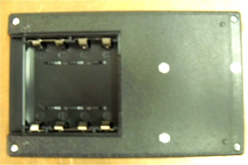
Click to zoom
Application Details
- Equipment Class
- DXX - Part 15 Low Power Communication Device Transmitter
- Date of Grant
- Oct 06, 2011
- Application Purpose
- Original Equipment
- Date of Application
- Oct 04, 2011
- Equipment Note
- RF sensor module
- Frequency Range
- 2400.89000000 - 2479.82000000
- Company
- Aplica Technologies Ltd.
- Country
- Israel
Documents & Files
Document Text
Text extracted from the exhibit documents filed with the FCC. Open a document above to read the original.
Users Manual
1 RF Module 2.4G User's Manual Revision 02 3/04/2011 2 Table of Contents 1 GENERAL DESCRIPTION ......................................................................................................3 2 DEVICE OPERATION ..............................................................................................................3 3 DETAILED DEVICE DESCRIPTION ....................................................................................3 4 DEVICE INSTALLATION .......................................................................................................4 5 DEVICE INTERFACE DESCRIPTION .................................................................................4 6 BATTERY INSTALLATION ...................................................................................................5 7 OPERATIONAL CHARACTERISTICS ................................................................................5 8 FCC PART 15 STATEMENT AND WARNINGS .................................................................6 3 1 General description The "RF Module 2.4G" is an end-point device of a general use wireless network application. It enables implementation of a transparent link of data transmission from a PC to any remote RS232 terminal. It also enables transmission of discrete signals to and from a PC application, The wireless network of point to multipoint topology shall include single RF Dongle 2.4G device and up to 5 RF Sensor devices. The RF Sensor is intended to any industrial use. 2 Device Operation The RF Module Sensor 2.4G device is intended for use as an end-point device in a wireless network constructed of at least on RF Dongle 2.4G device and 1 to 5 RF Module Sensor 2.4G devices. Refer also to the RF Dongle User's Manual for more information. 3 Detailed Device Description 1. Main interface connector J1 2. DC power supply Jack 3. Indication LED 4. Binding button 5. Battery housing (bottom side) ① ② ③ ④ ⑤ 4 4 Device Installation The RF Module Sensor is equipped with 3 magnets installed on the case internal surface. These magnets provide the required mounting elements to a metal surface. The device can be mounted to any other surface by any other adequate means. It can also serve as a set-top box. To operate the device, follow the following steps: - Set the required application cabling of the interface mating connector (see section "Interface description" for details. - Install the device at the required location. - Connect the interface mating connector to the interface connector of the device. - Connect the DC adapter plug to the DC jack. - Connect the AD/DC adapter to the AC power source socket. - The device is ready to use – Set up the wireless network according to the wireless network setup user's guide. 5 Device Interface Description The following table describes the functionality of each pin of the Interface Connector J1: Pin # Function Description 1 AI_2_L Alternate analog Input #2 2 AI_1 Analog Input #1 3 GND Signal Ground 4 AI_2 Analog Input #2 5 TX RS-232 Transmit 6 AI_3 Analog Input #3 7 DO_1 Discrete Output #1 8 DI_1 Discrete Input #1 9 DO_2 Discrete Output #2 10 DI_2 Discrete Input #2 11 GND Signal Ground 12 DI_3 Discrete Input #3 13 DO_3 Discrete Output #3 14 DI_4 Discrete Input #4 15 5V_out (through 220Ω) 5 volt drive source for external LED 16 DI_5 Discrete Input #5 17 5V_out 5 volt drive source for 33Ω (min) load. (Load current 150mA max.) 18 DI_6 Discrete Input #6 19 RX RS-232 Receive 20 DI_7 Discrete Input #7 21 GND Signal Ground 22 DI_8 Discrete Input #8 The user shall set a mating connector cabling according to the application requirement. 5 The mating connector type is: Part Designation: B2L 3.5/22 SN OR Order No: 1747850000 Manufacturer: Weidmuller 6 Battery Installation Four (4) alkaline type batteries of size AA shall be installed at the battery housing according to the marked polarity. CAUTION RISK OF EXPLOSION IF BATTERY IS REPLACED BY AN INCORRECT TYPE. DISPOSE OF USED BATTERIES ACCORDING TO THE INSTRUCTIONS 7 Operational Characteristics Power source: 1) 3-12 Volt DC 2) 4 X "AA" size alkaline batteries Current Consumption: Standby (no external load): 10uA typ. Operational (with max load): 250mA Operating Temperature: -10 to +45 °C Tx/Rx frequency Range: 2400 – 2483 MHz Output Tx power: +1dBm Internal Antenna Gain: +5.5dBi max. This device complies with Part 15 of the FCC Rules. Operation is subject to the following two conditions: (1) This device may not cause harmful interference, and (2) this device must accept any interference received, including interference that may cause undesired operation. Every system that includes the RF SENSOR module will have a label: “This product includes the modular RF sensor FCC ID:ZEMSENSOR” 6 8 FCC part 15 statement and warnings NOTE: This equipment has been tested and found to comply with the limits for a Class B digital device, pursuant to Part 15 of the FCC Rules. These limits are designed to provide reasonable protection against harmful interference in a residential installation. This equipment generates, uses and can radiate radio frequency energy and, if not installed and used in accordance with the instructions, may cause harmful interference to radio communications. However, there is no guarantee that interference will not occur in a particular installation. If this equipment does cause harmful interference to radio or television reception, which can be determined by turning the equipment off and on, the user is encouraged to try to correct the interference by one or more of the following measures: -- Reorient or relocate the receiving antenna. -- Increase the separation between the equipment and receiver. -- Connect the equipment into an outlet on a circuit different from that to which the receiver is connected. -- Consult the dealer or an experienced radio/TV technician for help. Warning! Changes or modifications to this equipment not expressly approved by the Kodak IL LTD could void the user’s authority to opera…
Text truncated - open the document above for the full version.
Block Diagram
Aplica Technologies Ltd. FCC ID:ZEMSENSOR Page 1 of 2 BLOCK DIAGRAM CC2510 SoC (uC + RF transceiver) RF SENSOR Module MAX3221 RS232 driver 74LVC14 buffer TLV2765 Op-amp DC Jack Printed Antenna TPS715A01 LDO FET MCP102 Power-on reset MAX6373 Watch Dog reset PolySwitch No-Pop Board to Board connector Right-Angle Connector RSTn 74LVC14 buffer ctrl 26Mhz
Cover Letter(s)
RF_160, Issue 02 Declaration of Authorization We Name: Aplica Technologies Ltd. Address: 12 HaLapid street, P.O.Box 7291 City: Petach-Tikva 49170 Country: Israel . Declare that: Name Representative of agent: ............. (1) Agent Company name: Hermon Laboratories Ltd. Address: Harakevet Industrial Zone City: Binyamina 30500 Country Israel is authorized to apply for Certification of the following product(s): Product description: RF sensor module . Type designation: 500-09898A . Trademark: Aplica . on our behalf. Date: March 27, 2011 Name: David Luzon Function: HW team manager Signature: Notes: (1): Required for FCC application (2): For FCC it must be the Grantee Code “owner” or the authorized agent.
Cover Letter(s)
FCC, Request for non-disclosure Date: 16-Jul-10 RF_501, Issue 6 Page 1 of 1 Company Name: Aplica Technologies Ltd. Address : 12 HaLapid street City: Petach-Tikva 49170 Country: Israel To: Telefication B.V ., Dept. FCC TCB Edisonstraat 12A 6902 PK ZEVENAAR The Netherlands Subject: Request for confidentiality FCC ID: ZEMSENSOR Reference number: ###### Dear FCC TCB, 1. Long-Term Confidentiality Pursuant to 47 CFR Section 0.459(a) & (b), we hereby requests non-disclosure and confidential treatment of the following materials submitted in support of FCC certification application: Bill(s) of Material Block Diagrams Operational Description Schematic Diagrams Tune-up Procedure Above materials contain secrets, proprietary and technical information, which would customarily be guarded from competitors under 47 CFR, section 0.457(d)(2). Disclosure or publication or any portion of this company confidential material to other parties could cause substantial competitive harm and provide unjustified benefits for competitors. 2. Short-Term Confidentiality (STC) Pursuant to Public Notice DA 04-1705 of the Commission’s policy, in order to comply with the marketing regulations in 47 CFR §2.803 and the importation rules in 47 CFR §2.1204, a pplicant hereby requests Short-Term Confidential treatment of the following materials (note 1): Internal Photos User’s Manual Test Set-up Photos External Photos Justification: Planned Release Date STC: (notes 2, 3, 4, 5) Date: March 27, 2011 Name and signature of applicant: David Luzon Notes: 1) A document or type of document can only have ONE type of confidentiality! 2) Short-Term confidentiality is in principle for 45 days from date of grant; it can be extended max 3 times (total time 180 days max.)! 3) FCC must be informed when marketing begins earlier. 4) Release takes place automatically thus extension must be requested in time. Telefication does not remind you of this! 5) Request for extension or for release must be received by Telefication at least 7 days before date of actual marketing or before expiration of the STC period
External Photos
Aplica Technologies Ltd. FCC ID:ZEMSENSOR Page 1 of 5 EXTERNAL PHOTOGRAPHS This document contains 4 photographs Aplica Technologies Ltd. FCC ID:ZEMSENSOR Page 2 of 5 Photograph No.1 RF sensor module front view Aplica Technologies Ltd. FCC ID:ZEMSENSOR Page 3 of 5 Photograph No.2 RF sensor module rear side view Aplica Technologies Ltd. FCC ID:ZEMSENSOR Page 4 of 5 Photograph No.3 RF sensor module rear side view with cover removed Aplica Technologies Ltd. FCC ID:ZEMSENSOR Page 5 of 5 Photograph No.4 RF sensor module side view
ID Label/Location Info
Aplica Technologies Ltd. FCC ID:ZEMSENSOR Page 1 of 2 Label location Label with FCC ID:ZEMSENSOR will be located at the rear side panel. The statement according to FCC part 15 §15.19(a)(3) is placed in Users Guide, page 5 (Application exhibit Users_Guide _20520). FCC ID:ZEMSENSOR ARBEL SHAI 28.10.10 28.10.10 01 382-02744A.P.I RF MODULE SENSOR LABEL P.I Transparent 3.5X2.5 77.5mm 12.5mm 43.5mm 15mm 131.5mm RF Module Sensor 2.4G Serial no P.N 382-02744A manufacturing date: THIS CLASS "B" DIGITAL APPARATUS COMPLIES WITH CANADIAN ICES-003. CET APPAREIL NUMERIQUE DE LA CLASSE "B" EST CONFORME A LA NORME NMB-003 DU CANADA. 1. Material - GE Lexan 8B35 Velvet matt 0.125 thick - kodak P.N 755-00352A 2. Adhesive - 3M 468 MP 0.13mm thick kodak P.N - 400-00392 3. First print - Black - conforming to ROHS - 755-00398A 4. Second print - PANTONE COOL GREY 2 C - conforming to ROHS - 755-00398A POWER: 3-12 Vdc, 250 mA FCC ID:ZEMSENSOR
Internal Photos
Aplica Technologies Ltd. FCC ID:ZEMSENSOR Page 1 of 7 INTERNAL PHOTOGRAPHS This document contains 6 photographs Aplica Technologies Ltd. FCC ID:ZEMSENSOR Page 2 of 7 Photograph No.1 RF sensor module internal view Aplica Technologies Ltd. FCC ID:ZEMSENSOR Page 3 of 7 Photograph No.2 RF sensor module internal view Aplica Technologies Ltd. FCC ID:ZEMSENSOR Page 4 of 7 Photograph No.3 RF sensor module PCB front view Aplica Technologies Ltd. FCC ID:ZEMSENSOR Page 5 of 7 Photograph No.4 RF sensor module PCB second side view Aplica Technologies Ltd. FCC ID:ZEMSENSOR Page 6 of 7 Photograph No.5 PCB second side view without shield Aplica Technologies Ltd. FCC ID:ZEMSENSOR Page 7 of 7 Photograph No.6 RF sensor antenna
Operational Description
RF Sensor Platform FCC ID:ZEMSENSOR RF Sensor Platform Aplica's advanced RF Sensor platform provides a cost effective solution for the deployment of a wireless network of remote sensors and automatic meter reading (AMR) elements. The "RF Module Sensor 2.4G" is an end-point device of a general use wireless network application. It enables implementation of a transparent link of data transmission from a PC to any remote RS232 terminal. It also enables transmission of discrete signals to and from a PC application, The wireless network of point to multipoint topology shall include single RF Dongle 2.4G device and up to 5 RF Sensor devices. The advanced platform is based on Texas Instruments state-of-the-art RF transceiver System on Chip (SoC) CC251x. These S0C’s combine the excellent performance of the CC251x with an industry-standard enhanced 8051 MCU, up to 32 KByte of in- system programmable flash memory and 4 KByte of RAM, and many other powerful features. The RF Sensor Platform supports a sub GHz operating frequency or a 2.4 GHz frequency and has an on-board 2.4 GHz meandered inverted F-Antenna. A 50 ohm SMA output is available for a user selected antenna. The RF Sensor Platform provides an RS232 or an RS485 serial interface and a USB 2.0 controller (the Dongle is attached to a USB port of the customer PC). RF Sensor Platform FCC ID:ZEMSENSOR Characteristics Specification System on Chip Assembly options CC251x SoC Operating Frequencies ISM Bands CC251x 2.4 GHz Supported Antennas On-Board 2.4GHa Meandered Inverted F-Antenna External option 50 ohm SMA female output Data Rate Rate 500 kbps maximum Modulation Formats FSK/GFSK/MSK/OOK/ASK Sensitivity CC111x Sub 1GHz: -110dBm CC251x 2.4GHz: -88dBm@250kbps; -98dBm@10kbps (1% PER) Serial Port Interface RS232 or RS485 Connector DB9 pin, Male USB Ports 1 USB 2.0 port Connector Mini USB 5 Pin Female SMD, B-Type General Purpose I/O Discrete Inputs 8 Inputs for dry-contacts/open drain/5V tolerant Discrete Outputs 3 TTL compatible Connector Weidmuller 22-pin connector, P/N: S2L-SMT3.5/22/90 SN A/D Channels 3 A/D channels, 12bit resolution. Input range (default): 0-12V Connector Weidmuller 22-pin connector, P/N: S2L-SMT3.5/22/90 SN Indicators LEDs 3 General Purpose LEDs (shared with discrete outputs) Power Supply Voltage Option#1: External 6-24VDC via EJ508A connector, or 2 pin; Option#2: External 3-6VDC via 2 pin header Environment Operating Temperature Industrial: -40ºC - 85ºC Compliance Designed to conform ESTI EN 300 220 and FCC CFR 47, part 15
Test Report
Hermon Laboratories Ltd. Harakevet Industrial Zone, Binyamina 30500, Israel Tel. +972-4-6288001 Fax. +972-4-6288277 E-mail: [email protected] Page 1 of 29 Report ID: APLEMC_FCC.20520.doc Date of Issue: 1/9/2011 ELECTRICAL TESTING 0839.01 TEST REPORT ACCORDING TO: FCC 47 CFR PART 15 subpart B class B FOR: Aplica Technologies Ltd. RF Sensor Module Model number: 500-09898A This report is in conformity with ISO/ IEC 17025. The "A2LA Accredited" symbol endorsement applies only to the tests and calibrations that are listed in the scope of Hermon Laboratories accreditation. The test results relate only to the items tested. This test report shall not be reproduced in any form except in full with the written approval of Hermon Laboratories Ltd. Report ID: APLEMC_FCC.20520.doc Date of Issue: 1/9/2011 Page 2 of 29 Table of contents 1 Applicant information .........................................................................................................................................................3 2 Equipment under test attributes ........................................................................................................................................3 3 Manufacturer information ..................................................................................................................................................3 4 Test details ........................................................................................................................................................................3 5 Tests summary ..................................................................................................................................................................4 6 EUT description .................................................................................................................................................................5 6.1 General information ...........................................................................................................................................................5 6.2 Ports and lines ...................................................................................................................................................................5 6.3 Support and test equipment ..............................................................................................................................................5 6.4 Changes made in EUT ......................................................................................................................................................5 6.5 Test configuration ..............................................................................................................................................................6 7 Emissions tests according to FCC 47CFR part 15 subpart B requirements ....................................................................7 7.1 Conducted emissions ........................................................................................................................................................7 7.2 Radiated emission measurements ..................................................................................................................................11 8 APPENDIX A Test equipment and ancillaries used for tests..........................................................................................21 9 APPENDIX B Measurement uncertainties ......................................................................................................................22 10 APPENDIX C Test laboratory description .......................................................................................................................23 11 APPENDIX D Specification references ...........................................................................................................................23 12 APPENDIX E Test equipment correction factors ............................................................................................................24 13 APPENDIX F Abbreviations and acronyms ....................................................................................................................29 Report ID: APLEMC_FCC.20520.doc Date of Issue: 1/9/2011 Page 3 of 29 1 Applicant information Client name: Aplica Technologies Ltd. Address: P.O.Box 7291, Petach-Tikva 49170, Israel Telephone: +972 3924 9393 Fax: +972 3924 9394 E-mail: [email protected] Contact name: Mr. Shay Ben Harush 2 Equipment under test attributes Product name: RF sensor module Product type: Transceiver Model number: 500-09898A Serial number: 2 Hardware version: V0 Receipt date: 10/13/2010 3 Manufacturer information Manufacturer name: Aplica Technologies Ltd. Address: P.O.Box 7291, Petach-Tikva 49170, Israel Telephone: +972 3924 9393 Fax: +972 3924 9394 E-Mail: [email protected] Contact name: Mr. Shay Ben Harush 4 Test details Project ID: 20520 Location: Hermon Laboratories Ltd. Harakevet Industrial Zone, Binyamina 30500, Israel Test started: 10/13/2010 Test completed: 1/02/2011 Test specification(s): FCC 47CFR Part 15, subpart B, class B Report ID: APLEMC_FCC.20520.doc Date of Issue: 1/9/2011 Page 4 of 29 5 Tests summary Test Status FCC 47CFR part 15, subpart B Section 15.107 Class B, AC power lines conducted emissions Pass Section 15.109 Class B, Radiated emissions Pass Testing was completed against all relevant requirements of the test standard. The results obtained indicate that the product under test complies in full with the requirements tested. The test results relate only to the items tested. Pass/ fail decision was based on nominal values. Name and Title Date Signature Tested by: Mr. S. Samokha, test engineer January 2, 2011 Reviewed by: Mrs. M. Cherniavsky, certification engineer January 10, 2011 Approved by: Mr. M. Nikishin, EMC and radio group manager January 11, 2011 Report ID: APLEMC_FCC.20520.doc Date of Issue: 1/9/2011 Page…
Text truncated - open the document above for the full version.
Test Report
Hermon Laboratories Ltd. Harakevet Industrial Zone, Binyamina 30500, Israel Tel. +972-4-6288001 Fax. +972-4-6288277 E-mail: [email protected] Page 1 of 73 Report ID: APLRAD_FCC.20520.doc Date of Issue: 1/9/2011 ELECTRICAL TESTING 0839.01 TEST REPORT ACCORDING TO: FCC 47 CFR PART 15 subpart C, section 15.249 FOR: Aplica Technologies Ltd. RF Sensor Module Model number: 500-09898A This report is in conformity with ISO/ IEC 17025. The "A2LA Accredited" symbol endorsement applies only to the tests and calibrations that are listed in the scope of Hermon Laboratories accreditation. The test results relate only to the items tested. This test report shall not be reproduced in any form except in full with the written approval of Hermon Laboratories Ltd. Report ID: APLRAD_FCC.20520.doc Date of Issue: 1/9/2011 Page 2 of 73 Table of contents 1 Applicant information .........................................................................................................................................................3 2 Equipment under test attributes ........................................................................................................................................3 3 Manufacturer information ..................................................................................................................................................3 4 Test details ........................................................................................................................................................................3 5 Tests summary ..................................................................................................................................................................4 6 EUT description .................................................................................................................................................................5 6.1 General information ...........................................................................................................................................................5 6.2 Ports and lines ...................................................................................................................................................................5 6.3 Support and test equipment ..............................................................................................................................................5 6.4 Changes made in EUT ......................................................................................................................................................5 6.5 Test configuration ..............................................................................................................................................................6 6.6 Transmitter characteristics ................................................................................................................................................9 7 Transmitter tests according to 47CFR part 15 subpart C requirements.........................................................................10 7.1 Field strength of emissions..............................................................................................................................................10 7.2 Band edge emission ........................................................................................................................................................45 7.3 Conducted emissions ......................................................................................................................................................53 7.4 Antenna requirements .....................................................................................................................................................56 7.5 Occupied bandwidth test .................................................................................................................................................57 8 APPENDIX A Test equipment and ancillaries used for tests..........................................................................................60 9 APPENDIX B Measurement uncertainties ......................................................................................................................61 10 APPENDIX C Test laboratory description .......................................................................................................................62 11 APPENDIX D Specification references ...........................................................................................................................62 12 APPENDIX E Test equipment correction factors ............................................................................................................63 13 APPENDIX F Abbreviations and acronyms ....................................................................................................................73 Report ID: APLRAD_FCC.20520.doc Date of Issue: 1/9/2011 Page 3 of 73 1 Applicant information Client name: Aplica Technologies Ltd. Address: P.O.Box 7291, Petach-Tikva 49170, Israel Telephone: +972 3924 9393 Fax: +972 3924 9394 E-mail: [email protected] Contact name: Mr. Shay Ben Harush 2 Equipment under test attributes Product name: RF sensor module Product type: Transceiver Model number: 500-09898A Serial number: 2 Hardware version: V0 Receipt date: 10/13/2010 3 Manufacturer information Manufacturer name: Aplica Technologies Ltd. Address: P.O.Box 7291, Petach-Tikva 49170, Israel Telephone: +972 3924 9393 Fax: +972 3924 9394 E-Mail: [email protected] Contact name: Mr. Shay Ben Harush 4 Test details Project ID: 20520 Location: Hermon Laboratories Ltd. Harakevet Industrial Zone, Binyamina 30500, Israel Test started: 10/13/2010 Test completed: 1/02/2011 Test specification(s): FCC 47 CFR Part 15, subpart C, §15.249 Report ID: APLRAD_FCC.20520.doc Date of Issue: 1/9/2011 Page 4 of 73 5 Tests summary Tes…
Text truncated - open the document above for the full version.
Test Setup Photos
Aplica Technologies Ltd. FCC ID:ZEMSENSOR Page 1 of 9 SETUP PHOTOGRAPHS This document contains 8 photographs Aplica Technologies Ltd. FCC ID:ZEMSENSOR Page 2 of 9 Photograph No.1 Setup for spurious emission measurements in the anechoic chamber below 30 MHz Aplica Technologies Ltd. FCC ID:ZEMSENSOR Page 3 of 9 Photograph No.2 Setup for radiated emission measurements in the anechoic chamber from 30 to 1000 MHz Aplica Technologies Ltd. FCC ID:ZEMSENSOR Page 4 of 9 Photograph No.3 Setup for radiated emission measurements in the anechoic chamber above 1000 MHz Aplica Technologies Ltd. FCC ID:ZEMSENSOR Page 5 of 9 Photograph No.4 Setup for radiated emission measurements at the OATS from 1 to 18 GHz Aplica Technologies Ltd. FCC ID:ZEMSENSOR Page 6 of 9 Photograph No.5 Setup for radiated emission measurements at the OATS from 18 to 25 GHz Aplica Technologies Ltd. FCC ID:ZEMSENSOR Page 7 of 9 Photograph No.6 Setup for radiated emission measurements at the OATS, EUT close view Aplica Technologies Ltd. FCC ID:ZEMSENSOR Page 8 of 9 Photograph No.7 Setup for occupied bandwidth measurements Aplica Technologies Ltd. FCC ID:ZEMSENSOR Page 9 of 9 Photograph No.8 Setup for conducted emission measurements on the AC power lines
Contact Information
Applicant
David Luzon(HW team manager)
Technical Contact
Hermon Laboratories Ltd.Michael
+972 4626 8440
Israel
Test Firm
Hermon Laboratories Ltd.Alexander Usoskin
Technical Specifications
| # | Rule Parts | Frequency Range | Power Output |
|---|---|---|---|
| 1 | 15C | 2.40 GHz - 2.48 GHz | - |
Other Applications from Aplica Technologies Ltd.
ZEMDONGEL
Oct 06, 2011RF dongle 2.4G
Equipment Class
DXX - Part 15 Low Power Communication Device Transmitter